Polyimide Tape for PCB Masking: Avoiding Edge Lift and Residue
Datasheet heat limits rarely guarantee assembly success. Learn how true protection relies on proper surface prep, application pressure, and controlled removal timing during thermal processing.
An amber tape can come through a soldering cycle looking untouched and still have failed at its job. The problems appear when it is peeled away: flux has reached the edge of a contact, a sticky line remains beside the masked area, or a thermocouple is no longer where it was placed.
These failures are easily lumped together as “the tape did not withstand the heat.” Usually, that diagnosis is too simple. The polyimide film may have survived exactly as expected. However, as shown in Figure 1, PCB masking involves a multilayer stack. It is not just a film. What failed may have been the seal at the edge, the adhesive after thermal exposure, the way the tape was applied, or the conditions under which it was removed.
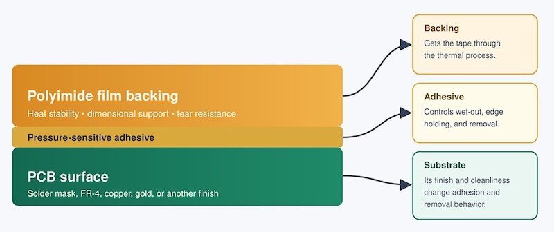
Figure 1. Masking is a complex, layered construction, not just a film
That is the useful way to approach polyimide tape for PCB masking: not as an amber film with an impressive maximum-temperature number, but as a temporary process material. It has to protect a defined area through a defined soldering cycle and then leave the board in an acceptable condition.
Different PCB Masking Jobs Have Different Demands
“PCB masking” can describe several quite different jobs. During wave or selective soldering, tape may protect gold fingers, connector contacts, or areas that must remain free of solder and flux. In reflow work, it may cover a surface or hold a thermocouple during profiling. On a prototype bench, the same material may provide temporary insulation or protection during rework.
Each job has its own likely failure. A wave-solder mask depends heavily on the boundary exposed to flux and solder. Thermocouple attachment is more concerned with movement during the cycle and removal afterward. Using temporary insulation on a prototype says little about its suitability for permanent electrical insulation.
Polyimide film is attractive because it is thin and dimensionally stable under heat. Those properties explain why the tape can be used in a high-temperature process. They do not tell an engineer whether its adhesive will hold the edge or come cleanly from FR-4, solder mask, copper, or gold.
The Datasheet Temperature Value Isn’t Enough
A statement such as “resists 260°C” looks decisive on a datasheet or catalog page. Without a duration, substrate, test method, and removal condition, it is not enough to approve a masking tape.
Peak temperature is only one part of the exposure. Preheat, repeated cycles, process chemistry, and the delay before removal can all change the result. There is also a difference between an intact film and a functional tape construction. The backing may look normal while the adhesive has flowed at the edge, increased in peel force, or transferred to the board.
A common industry shortcut assumes silicone is always for high temperature and acrylic is not. However, published products show why broad rules about adhesive chemistry are unreliable. For example, 3M’s 5413 is described as a polyimide tape with silicone adhesive for PCB solder masking. Alternatively, 3M’s 7419 tape uses silicone-free acrylic adhesive and is reported to remove cleanly from FR-4 and gold after 10 minutes at 260°C. The specifications are not interchangeable, which shows why the shortcut cannot be trusted. Formulation and the validated process window matter more than the family name.
Nor is polyimide automatically required whenever a PCB is exposed to heat. Tesa 4331 uses a polyester/nonwoven backing and silicone adhesive. Its published information states that it withstands up to 200°C for 30 minutes and includes wave-solder masking. That doesn’t make PET “better.” The point is that selection should follow the temperature-time profile and masking requirement, not film color.
When reviewing published technical data, ask what the temperature claim actually describes. If the answer does not cover the complete tape, the relevant substrate, exposure time, and removal result, treat it as screening information—not production approval.
The Problem Starts at the Edge
Most of a masking strip can remain firmly attached after the masking line has already failed. The boundary deserves closer inspection than the center.
A pressure-sensitive adhesive requires intimate contact with the board. Dust, oil, fingerprints, process residues, and uneven solder-mask texture can leave channels at the boundary. Pads, legends, vias, and connector geometry make sealing harder. A stiff tape may bridge a step rather than follow it.
Application technique matters too. Pulling the tape tight may look neat, but stored tension can encourage the edge to retract when heated. Light finger contact may hold the strip while leaving the boundary insufficiently bonded. Moving to the highest-tack option can create a removal problem without correcting poor contact.
If solder or flux has crossed the mask, inspect the boundary before changing materials. The strip may remain attached while a small boundary gap allows flow or solder to reach the protected area (Figure 2). Look for a lifted corner, a wrinkle, a board step, or an unbonded path. Use an assembly-approved cleaning method, let the surface dry, place the tape without stretching, and apply repeatable edge pressure. On narrow gold fingers, width tolerance and placement may matter as much as nominal adhesion.
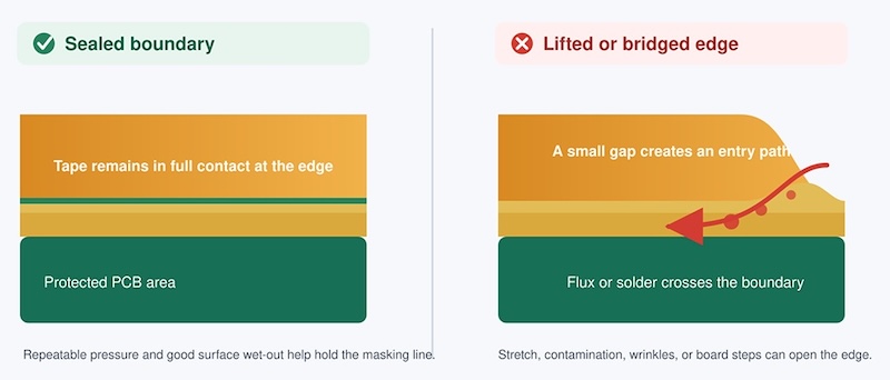
Figure 2. Edge effects are critical in PCB masking with polyimide tape
The practical test is not whether the roll feels sticky. It is whether an operator can create the same sealed boundary on successive boards without unusual skill or extra rework.
Residue Appears Only After Tape Removal
Residue is a different failure and should be investigated separately. The tape may hold its position, maintain a sharp boundary, and survive the oven. Only after removal does a sticky line, stain, or patch of transferred adhesive become visible.
Start with the actual thermal history, not just the oven peak. A long preheat, second pass, or delay before removal can age the adhesive beyond the original trial. Flux and cleaning chemistry may affect the adhesive-board interface. A peel result on stainless steel cannot be assumed to predict removal from solder mask, FR-4, gold, or copper.
Removal is another process variable. Tape pulled rapidly from a cold board may behave differently from tape removed warm at a controlled angle. No universal “remove hot” or “remove cold” rule fits every adhesive and substrate. Compare defined removal windows, select an acceptable one, and put that condition in the work instruction.
As Table 1 outlines, the appearance of the defect gives useful clues.
Table 1. Investigation guidelines based on defect type
| What appears after processing | Where to investigate first |
|---|---|
| One corner or edge has lifted | Surface wet-out, tape tension, local geometry, and application pressure |
| Flux or solder crossed the boundary | The edge seal, wrinkles, steps, and masking placement |
| A sticky line remains after removal | Total heat exposure, chemical contact, adhesive aging, and removal condition |
| Tape or thermocouple moved | Tape width and placement, wire tension, and adhesion after heating |
Agree on acceptance language before the trial. “Removes cleanly” is too vague if process engineering, quality, and production interpret it differently. State whether a visible stain is unacceptable, whether wiping is allowed, how tack is checked, and whether contacts require magnified inspection. The result then becomes reproducible rather than subjective.
One Good Board Isn’t a Process
Prototype work is forgiving in ways that production is not. One engineer may carefully clean a board, press every edge, and remove the tape immediately. A production line involves different operators, board lots, working times, and placement variation. A tape that succeeds once may still be a poor production choice if it needs constant adjustment.
Repeat the trial across several boards and, where possible, more than one operator. Include the board finishes used in the actual build. Check whether the width allows manual placement without covering a neighboring feature. For thermocouple attachment, reproduce the wire direction and tension; a stationary coupon does not represent a wire being pulled through a heating cycle.
Static control also belongs in the application definition. A low-static polyimide tape may be appropriate when unwinding or removal occurs near electrostatic-discharge-sensitive devices, but it should not be specified automatically for every PCB. The assembly’s ESD control plan and component sensitivity should determine whether that feature is required.
Finally, do not turn a temporary masking result into a permanent insulation claim. Long-term electrical insulation involves service temperature, dielectric requirements, aging, flame performance, chemical exposure, and compatibility with the complete insulation system. A tape that holds during reflow has passed a temporary process test—nothing more.
Test With Real Production Conditions
A useful trial follows the tape from application through removal. Use the real PCB finish, production width, normal application tool, and repeatable pressure. Run the normal preheat and soldering profile, including multiple passes where applicable. Keep the flux, cleaning sequence, cooling time, and removal method realistic.
After removal, inspect more than the middle of the masked area. Check the boundary for intrusion, shifted edges, and wrinkles; examine sensitive contacts at suitable magnification; and record stain, tack, transfer, or extra cleaning. Repeatability deserves its own result: three carefully made boards do not prove that thirty will behave the same way on the line.
When engineers are narrowing the candidate materials, a PCB masking tape selection guide can help organize the board, process, and removal details before bench evaluation. It cannot replace the trial. Peel data on steel is useful for comparing tapes under a common laboratory method; it is not a qualification on the actual PCB.
Record the accepted conditions: tape identification and lot, board finish, masking location, application method, thermal profile, chemical exposure, removal window, and inspection criteria. If a later batch behaves differently, the process team has a useful basis for investigating what changed.
Polyimide tape earns its place in electronics assembly by providing a thin, heat-stable temporary mask. That advantage can disappear when the adhesive, board surface, edge geometry, or removal condition falls outside the tested window.
A tape has proven itself only when the protected area remains protected, and the board surface is acceptable after removal. Neither the amber film nor the highest number on the datasheet can make that decision.
All images used courtesy of Jiaxing Risure New Material Co., Ltd.