8 Channel Digital – 2 Channel Analog Isolator Module
The project presented here features an 8-channel digital and 2-channel analog isolator. The board is equipped with 6 forward digital isolators and 2 reverse digital isolators, in addition to 2 analog isolators.
The project presented here features an 8-channel digital and 2-channel analog isolator. The board is equipped with 6 forward digital isolators and 2 reverse digital isolators, in addition to 2 analog isolators.
The digital isolators boast an impressive 5000 VRMS isolation rating, as per UL1577 standards. Meanwhile, the analog isolators are certified to provide reinforced galvanic isolation of up to 5 kVRMS, adhering to VDE V 0884-11 and UL1577 standards. Furthermore, they support a working voltage of up to 1.5 kVRMS. The digital isolators are capable of supporting data rates of up to 100 Mbps.
Features
- Power Input 5V DC
- Level Translation Range: 2.25V to 5.5V
- 2 x Power LED Low Side and High Side
- 6 Channel Forward, 2 Channel Reverse Digital Isolator
- 2 Channel Analog Isolator (Current and Voltage Sense)
- Analog Output (Differential Signal)
- 100 Mbps data rate (Digital Isolator)
- Header Connector provided to access Digital I/Analog and Power Input and Output
- Robust isolation barrier
- 100-year projected lifetime at 1500 VRMS working voltage
- Up to 5000 VRMS isolation rating
- Up to 12.8 kV surge capability
- ±100 kV/µs typical CMTI
- Default output high (Digital)
- PCB dimensions: 4 51.44 x 28.73 mm
The 8-channel digital isolator
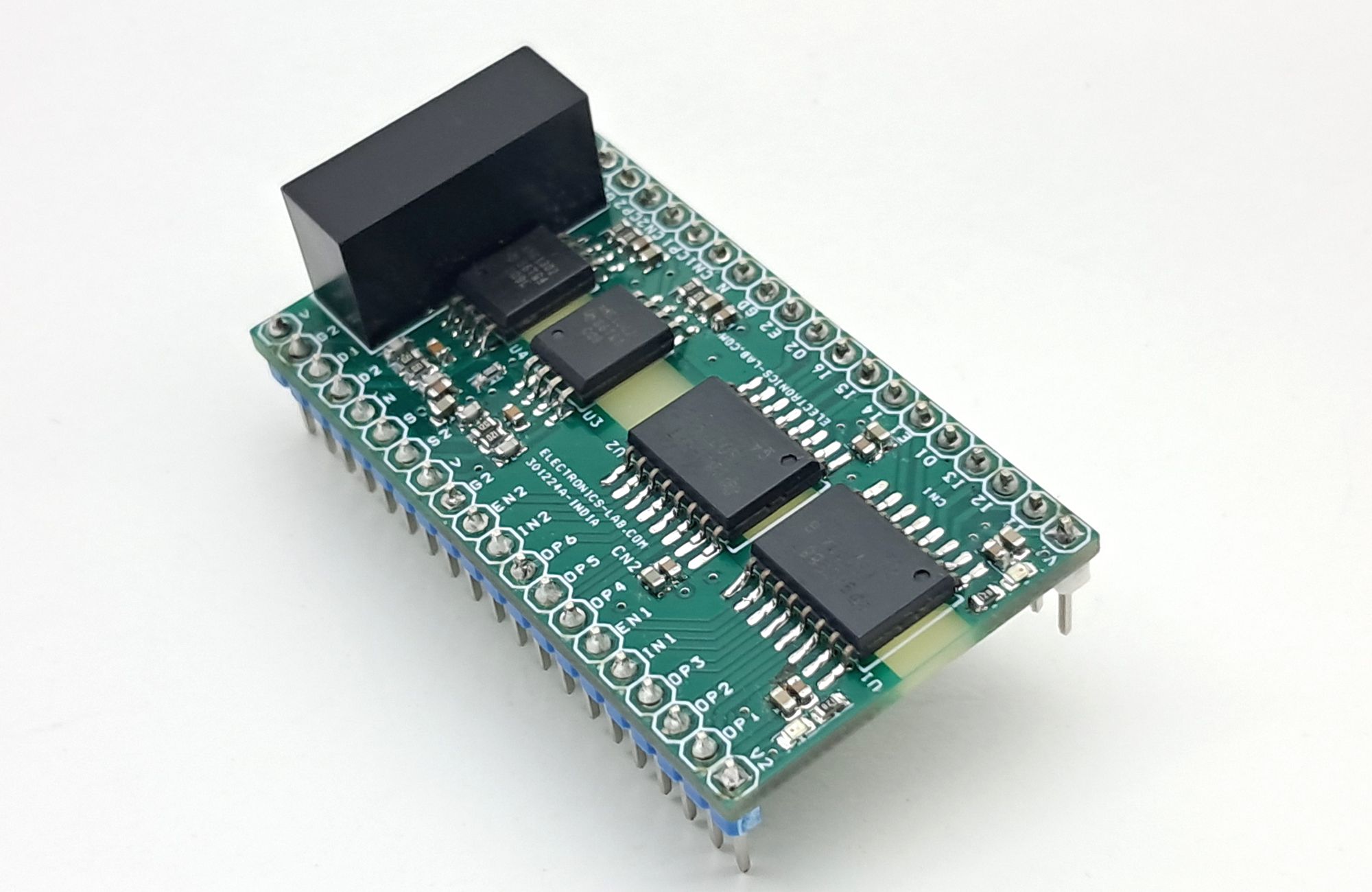
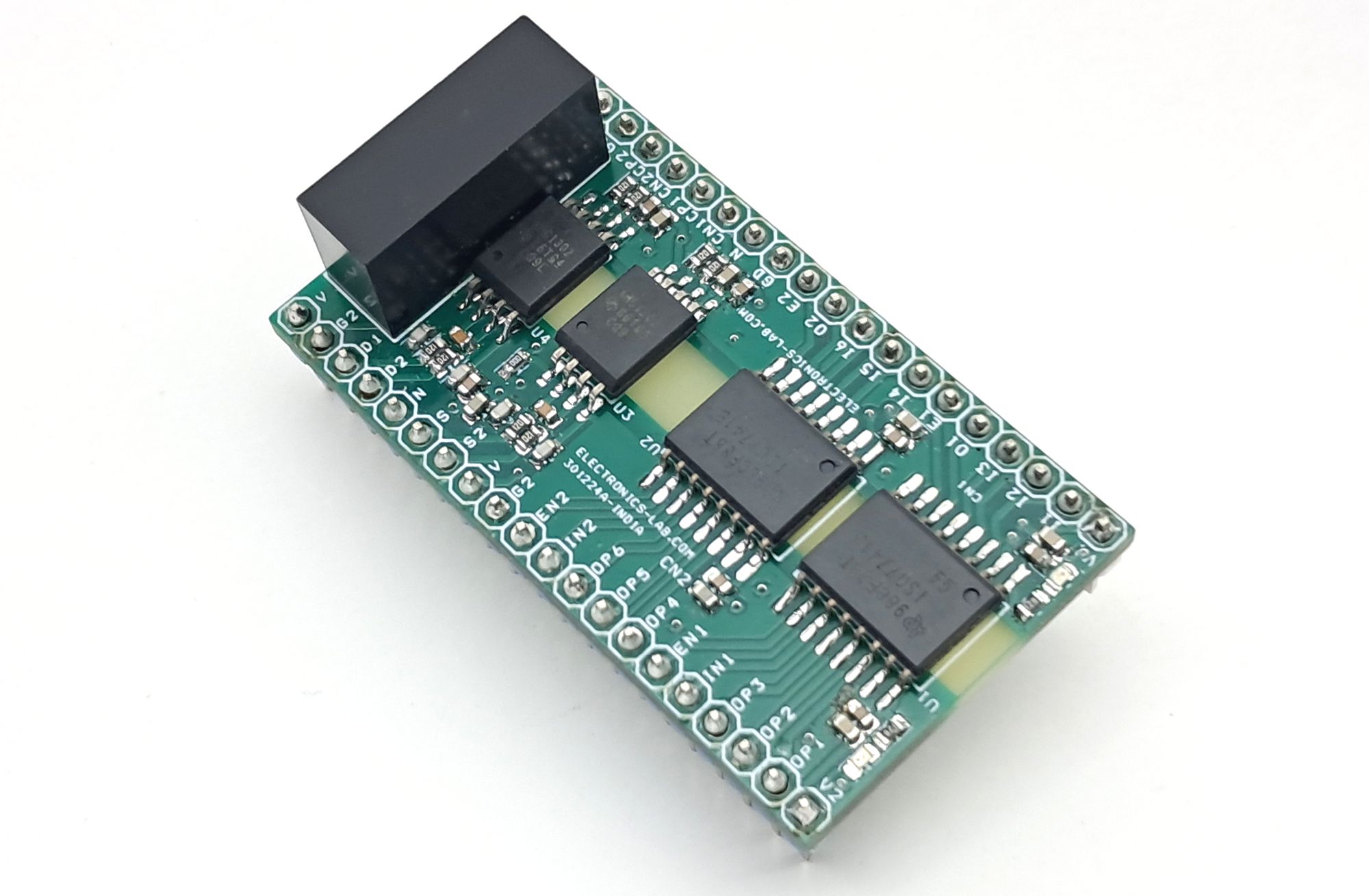
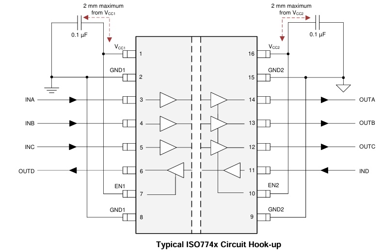
The board consists of 2 x ISO7741 chips, which provide 6 channels of forward digital isolation and 2 channels of reverse digital isolation. Notably, all outputs are normally high, and the ENABLE pins can be used to disable them. By connecting the Enable 1 and Enable 2 pins to GND on their respective sides, all outputs can be put in a LOW state, effectively disabling them. In the event of input power or signal loss, the output will default to a high state. The level translation range for these isolators is between 2.25V and 5.5V. Additionally, they exhibit high electromagnetic immunity, reducing noise and preventing high voltages from traveling to the main unit.
- Output enables 1. Output pins on side 1 are enabled when EN1 is high or open and in high-impedance state when EN1 is low.
- Output enables 2. Output pins on side 2 are enabled when EN2 is high or open and in high-impedance state when EN2 is low.
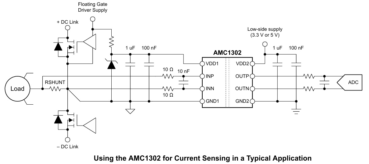
2 Channel Precision, ±50-mV Input, Reinforced Isolated Amplifier (AMC1302)
The board also consists of 2 x channel AMC1302 analog isolated Amplifiers with ±50-mV Inputs; these amplifiers can be used to measure the current as well as voltage. The output is differential and can be directly interfaced to the ADC of the host.
Power Supply
The board features a 5V input, 5V output isolated DC-DC converter, where the input side is connected to the low-side power (host side) and the output is connected to the high-side. The system operates with a 5V power supply on both sides of the isolation barrier. However, if the supply range differs, it is recommended to replace the DC-DC converter to ensure compatibility with the specific power requirements. Additionally, the digital and analog isolators on the board support both 5V and 3.3V supplies on the high-side and low-side, providing flexibility in terms of voltage compatibility
- Low-Side (Host/Micron troller) Side 5V, High-Side 5V Use B0505S-2WR3 DC-DC Converter (Input 5V, Output 5V)
- Low-Side (Host/Micron troller) Side 5V, High-Side 3.3V Use B0503S-2WR3 DC-DC Converter (Input 5V, Output 3.3V)
- Low-Side (Host/Micron troller) Side 3.3V, High-Side 3.3V Use B0303S-2WR3 DC-DC Converter (Input 5V, Output 3.3V)
Analog Input
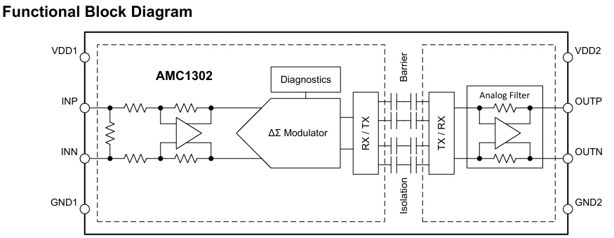
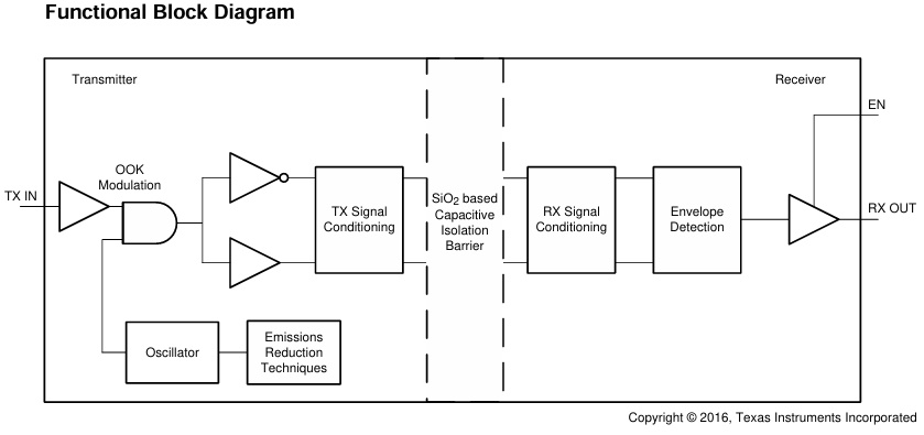
The differential amplifier input stage of the AMC1302 feeds a second-order, switched-capacitor, feed-forward ΔΣ modulator. The gain of the differential amplifier is set by internal precision resistors with a differential input impedance of RIND. The modulator converts the analog input signal into a bitstream that is transferred across the isolation barrier, as described in the Isolation Channel Signal Transmission section. There are two restrictions on the analog input signals INP and INN. First, if the input voltages VINP or VINN exceed the range specified in the Absolute Maximum Ratings table, the input currents must be limited to the absolute maximum value, because the electrostatic discharge (ESD) protection turns on. In addition, the linearity and parametric performance of the device are ensured only when the analog input voltage remains within the linear full-scale range (VFSR) and within the common-mode input voltage range (VCM) as specified in the Recommended Operating Conditions table.
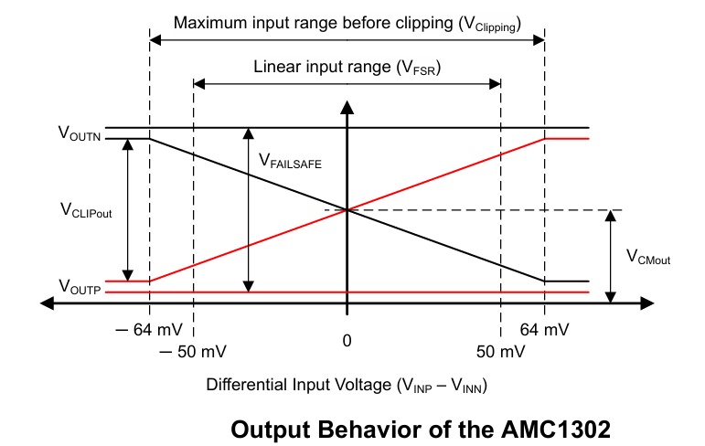
Analog Output
The AMC1302 offers a differential analog output comprised of the OUTP and OUTN pins. For differential input voltages (VINP – VINN) in the range from –50 mV to 50 mV, the device provides a linear response with a nominal gain of 41. For example, for a differential input voltage of 50 mV, the differential output voltage (VOUTP – VOUTN) is 2.05 V. At zero input (INP shorted to INN), both pins output the same common-mode output voltage VCMout, as specified in the Electrical Characteristics table. For absolute differential input voltages greater than 50 mV but less than 64 mV, the differential output voltage continues to increase in magnitude but with reduced linearity performance. The outputs saturate at a differential output voltage of VCLIPout, as shown in Figure, if the differential input voltage exceeds the VClipping value.
The AMC1302 is a precision, isolated amplifier with an output separated from the input circuitry by an isolation barrier that is highly resistant to magnetic interference. This barrier is certified to provide reinforced galvanic isolation of up to 5 kVRMS according to VDE V 0884-11 and UL1577, and supports a working voltage of up to 1.5 kVRMS. The isolation barrier separates parts of the system that operate on different common-mode voltage levels and protects the low-voltage side from hazardous voltages and damage. The input of the AMC1302 is optimized for direct connection to a low-impedance shunt resistor or other low-impedance voltage source with low signal levels. The excellent DC accuracy and low temperature drift supports accurate current control in PFC stages, DC/DC converters, AC-motor and servo drives over the extended industrial temperature range from –40°C to +125°C
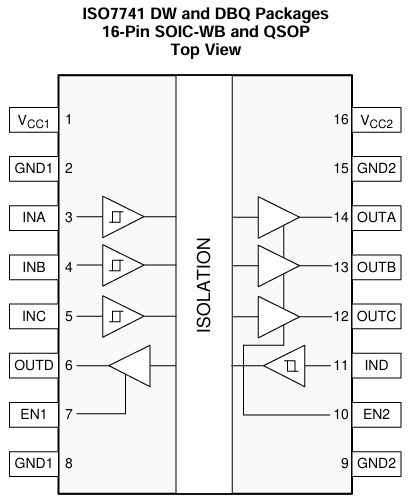
The ISO7741 device is a high-performance, quad-channel digital isolator with 5000 VRMS isolation ratings per UL 1577. This family includes devices with reinforced insulation ratings according to VDE, CSA, TUV, and CQC. The ISO7741B device is designed for applications that require basic insulation ratings only. The ISO7741 device provides high electromagnetic immunity and low emissions at low power consumption while isolating CMOS or LVCMOS digital I/Os. Each isolation channel has a logic input and output buffer separated by a double capacitive silicon dioxide (SiO2) insulation barrier. These devices come with enable pins which can be used to put the respective outputs in high impedance for multi-master driving applications and to reduce power consumption. The ISO7741 device has three forward and one reverse-direction channel.
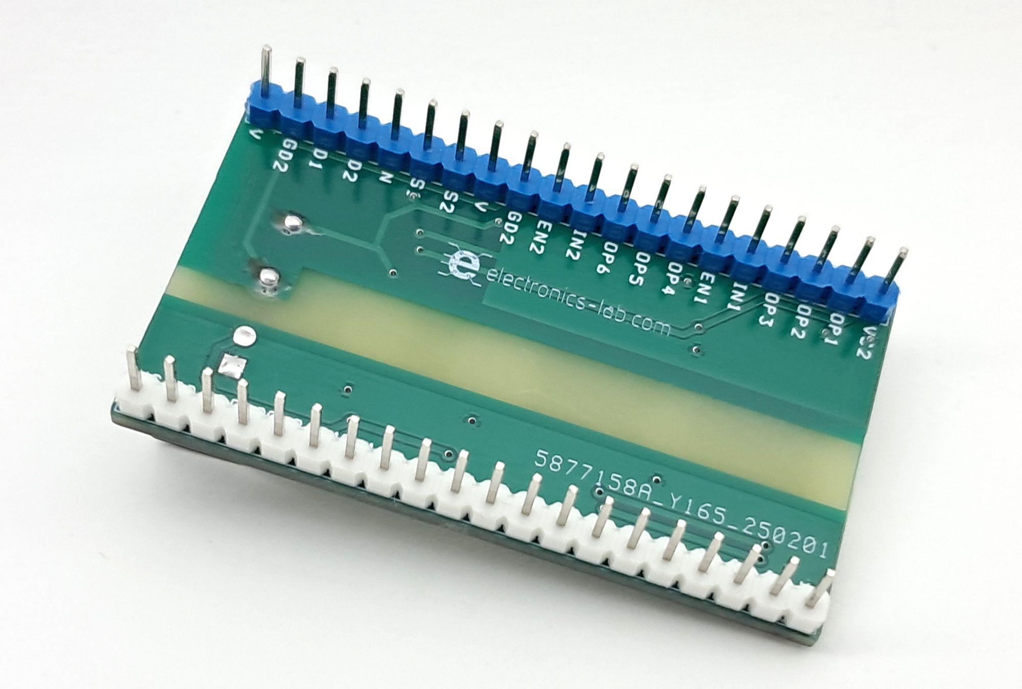
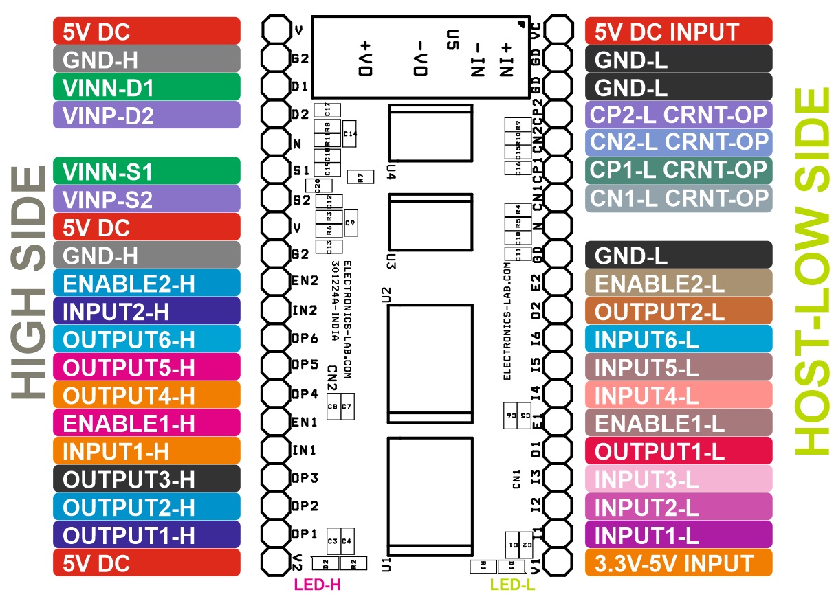
Connections
- CN1: Pin1= V1 5V DC Input, Pin 2 = Digital Input 1, Pin 3 = Digital Input 2, Pin 4 = Digital Input 3, Pin 5 = Digital Output 1L, Pin 6 = Enable 1L, Pin 7 = Digital Input 4, Pin 8 = Digital Input 5, Pin 9 = Digital Input 6, Pin 10 = Digital Output 2L, Pin 11 = Enable L2, Pin 12= GD-L, Pin 13 = NC, Pin 14 = CN1, Pin15= CP1, Pin 16 = CN2, Pin 17 = CP2, Pin 18 GD-L, Pin 19 = GD-L, Pin 20 = VC 5V DC Input
- CN2: Pin 1 = V2 5V DC, Pin 2 = Digital Output 1H, Pin 3 = Digital Output 2H, Pin 4 = Digital Output 3H, Pin 5 = Digital Input 1H, Pin 6 = Enable 1H, Pin 7 = Digital Output 4H, Pin 8 = Digital Output 5H, Pin 9 = Digital Output 6H, Pin 10 = Input 2H, Pin 11=Enable 2H, Pin 12 = GD-H, Pin 13=V 5V DC, Pin 14 = VINP-S2, Pin 15 = VINN-S1, Pin 16=NC, Pin 17 =VINP-D2, Pin 18 = VINN-D1, Pin 19=GD-H, Pin 20 = V 5V DC
- D1: Power LED V1 (Digital Isolator Low-Side)
- D2: Power LED V2 (Digital Isolator High-Side)
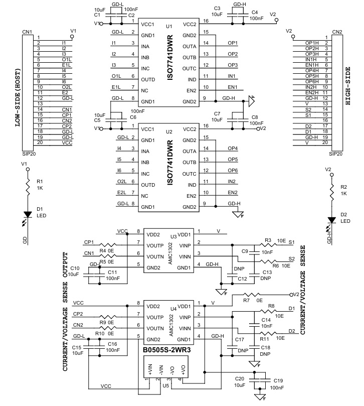
Schematic
Parts List
| NO. | QNTY. | REF. | DESC. | MANUFACTURING | SUPPLIER | SUPPLIER PART NO |
|---|---|---|---|---|---|---|
| 1 | 2 | CN1,CN2 | SIP20 | WURTH | DIGIKEY | 732-5329-ND |
| 2 | 7 | C1,C3,C5,C7,C10,C15,C20 | 10uF/10V CERAMIC SMD SIZE 0603 | YAGEO/MURATA | DIGIKEY | |
| 3 | 7 | C2,C4,C6,C8,C11,C16,C19 | 100nF/10V CERAMIC SMD SIZE 0603 | YAGEO/MURATA | DIGIKEY | |
| 4 | 2 | C9,C14 | 10nF/10V CERAMIC SMD SIZE 0603 | YAGEO/MURATA | DIGIKEY | |
| 5 | 4 | C12,C13,C17,C18 | DNP | |||
| 6 | 2 | D1,D2 | LED RED SMD SIZE 0603 | DIGIKEY | 5962-XL-1608SURC-06TR-ND | |
| 7 | 2 | R1,R2 | 1K 5% SMD SIZE 0605 | YAGEO/MURATA | DIGIKEY | |
| 8 | 4 | R3,R6,R8,R11 | 10E 5% SMD SIZE 0603 | YAGEO/MURATA | DIGIKEY | |
| 9 | 5 | R4,R5,R7,R9,R10 | 0E SMD SIZE 0603 | YAGEO/MURATA | DIGIKEY | |
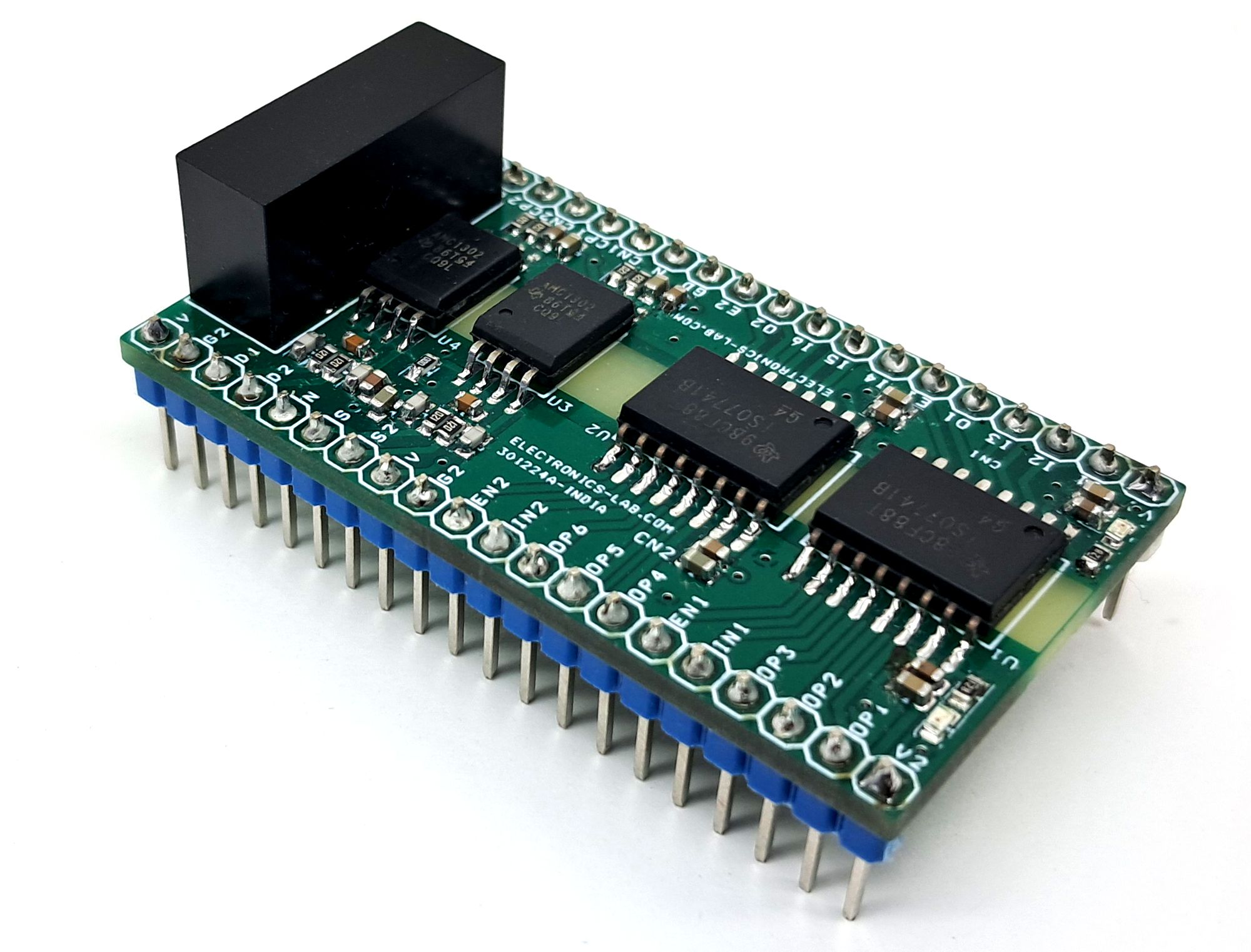
| 10 | 2 | U1,U2 | ISO7741DWR | TI | DIGIKEY | 296-47781-1-ND |
| 11 | 2 | U3,U4 | AMC1302 | TI | DIGIKEY | 296-50923-1-ND |
| 12 | 1 | U5 | B0505S-2WR3 DC-DC CONVERTER 5V IN, 5V OUT | MORNSUN | DIGIKEY | 2725-B0505S-2WR3-ND |
Connections
Diagrams
Gerber View
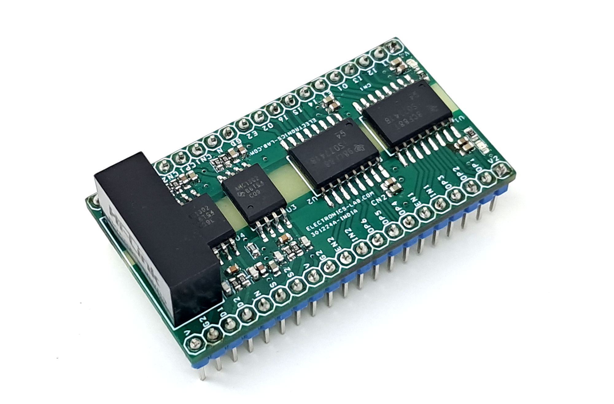
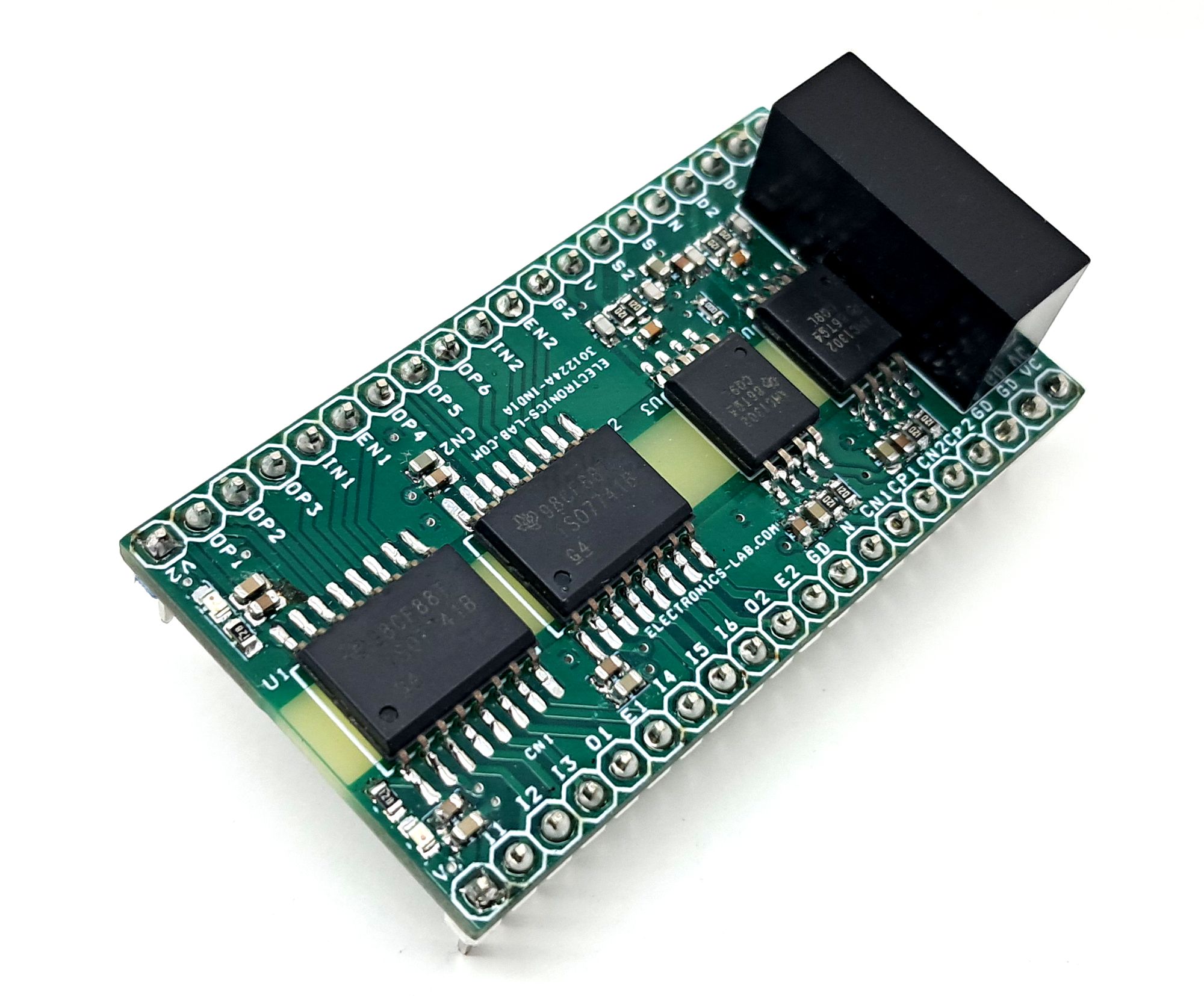
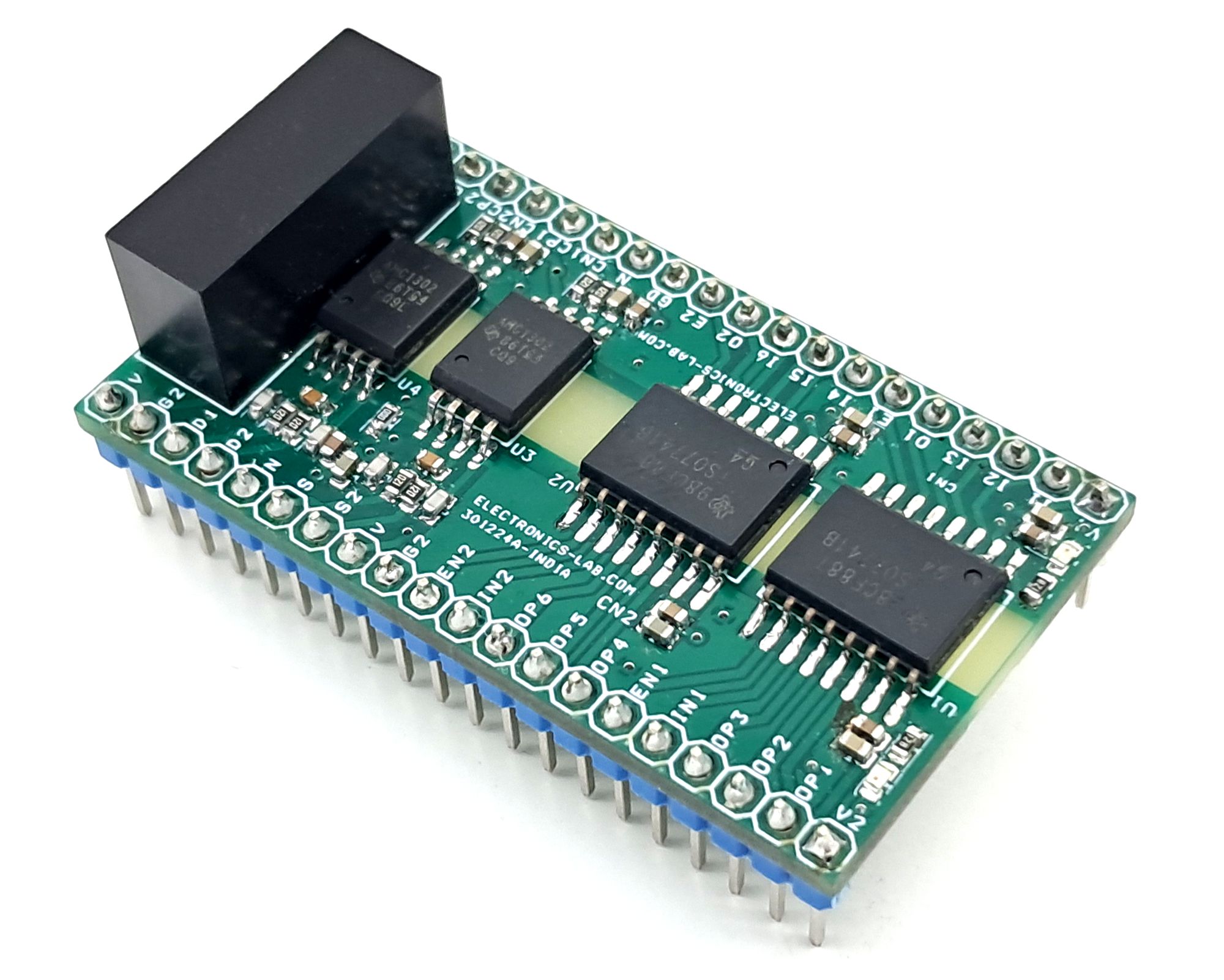
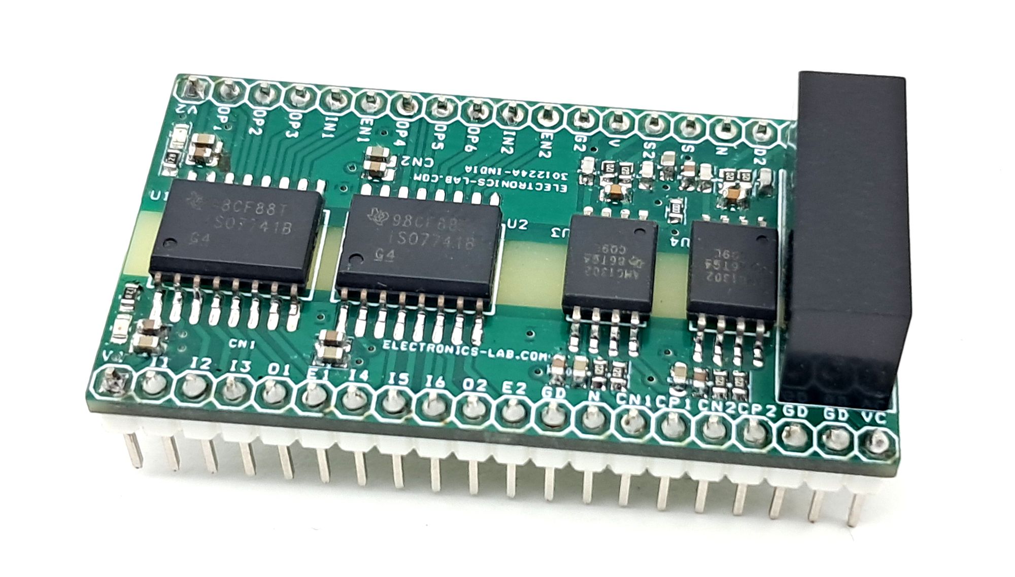
Photos