Laser distance sensor with OLED display and RP2040
This article implements a laser distance sensor with OLED display and RP2040, using the VL53L0x laser distance sensor. We will use a really small 0.49-inch OLED display that communicates with RP2040 via I2C.
This article implements a laser distance sensor with OLED display and RP2040, using the VL53L0x laser distance sensor. We will use a really small 0.49-inch OLED display that communicates with RP2040 via I2C.
By distance, I mean we will be able to measure how far in millimeters an object is from our VL53L0x laser sensor. This is without making any physical contact with the sensor, just over the air. There are many applications for this kind of measurement, for example, in robotics. One would be able to use such a sensor in an obstacle-avoiding robot.
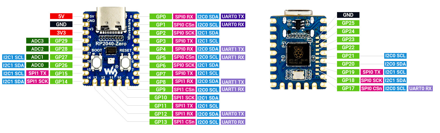
The choice of the Raspberry Pi RP2040 as our controller is because it is cheap and widely available. That is, while also being able to be programmed in both Arduino and microPython. In my case, specifically, I have a Waveshare RP2040 Zero version, which is very small and fits in a corner of the breadboard.
I have chosen to program this tutorial in Arduino using the Arduino IDE 2.x.x, and have not tested this code in any other version (e.g, 1.8.x) nor other IDEs.
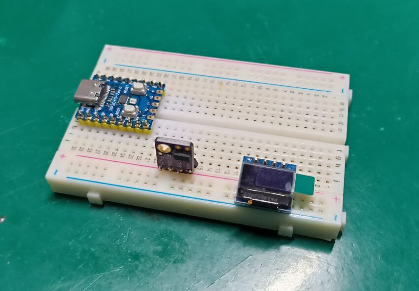
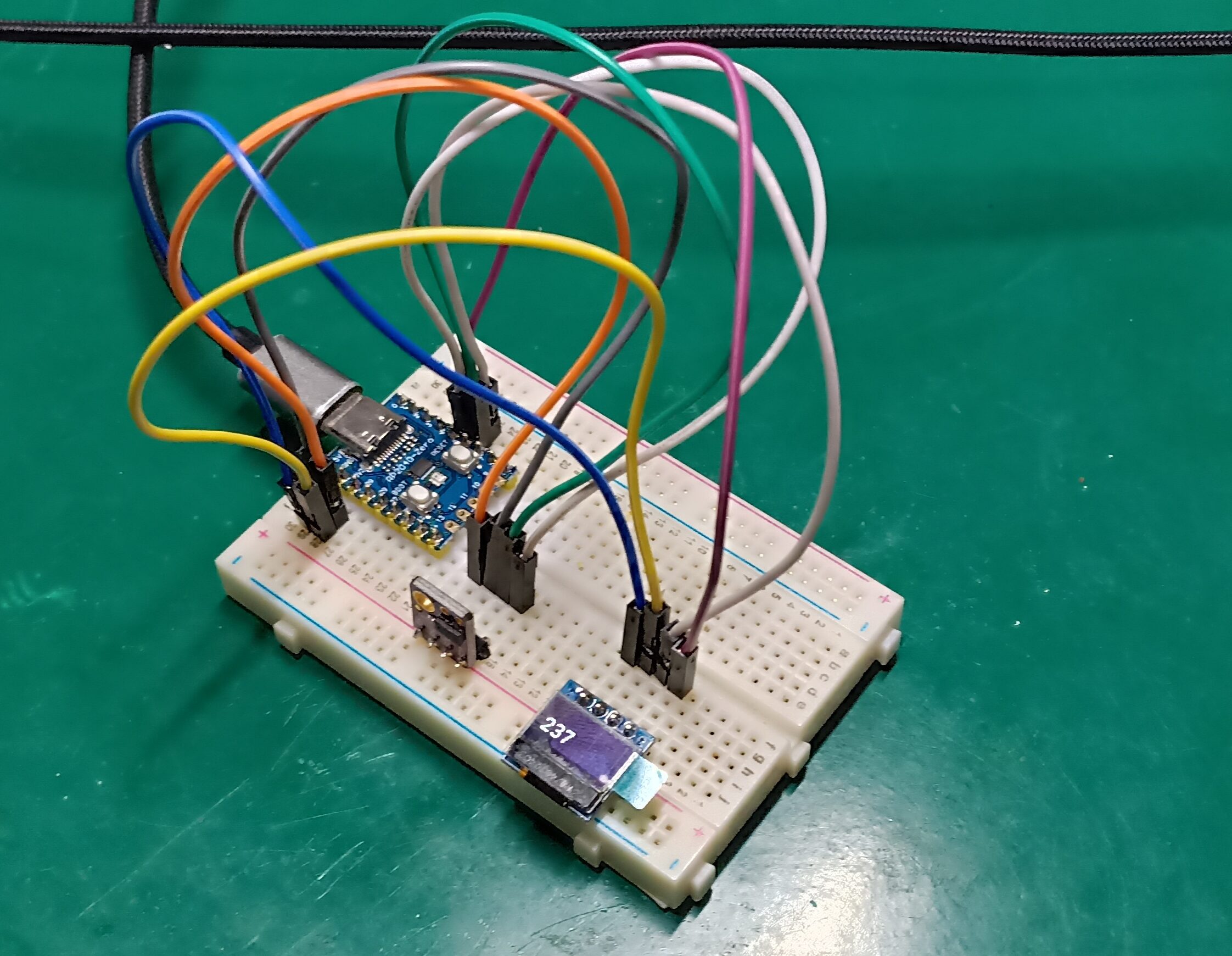
The circuit for this article will be supplied straight from a USB connection, using the USB-C available in the RP2040 Zero seen in the image above. Both our OLED screen and distance sensor will receive 3.3V and GND from the RP2040 Zero board. So, no worries about power conversion and external power, everything comes via USB cable.
As stated above, both the 0.49” OLED display and the VL53L0x distance sensor use an I2C port for communication with our microcontroller. I have implemented such communication using I2C0 SDA and I2C0 SCL on pins GP0 and GP1. In case you are using an Arduino UNO for this tutorial, just connect SDA and SCL to A4 and A5.
Getting to know the sensor and OLED
Our tiny 0.49-inch OLED display is monochromatic, meaning it shows a single color (in my case, it is white). There are other variants and colors, depending on what and where you buy it. In our tutorial, we will be using the u8g2lib library for Arduino to control it, as seen here.
Using this I2C bus scanner I found this OLED display to be on address 0x3C. You don’t need to worry about this, since it is hardcoded into the u8g2lib library.
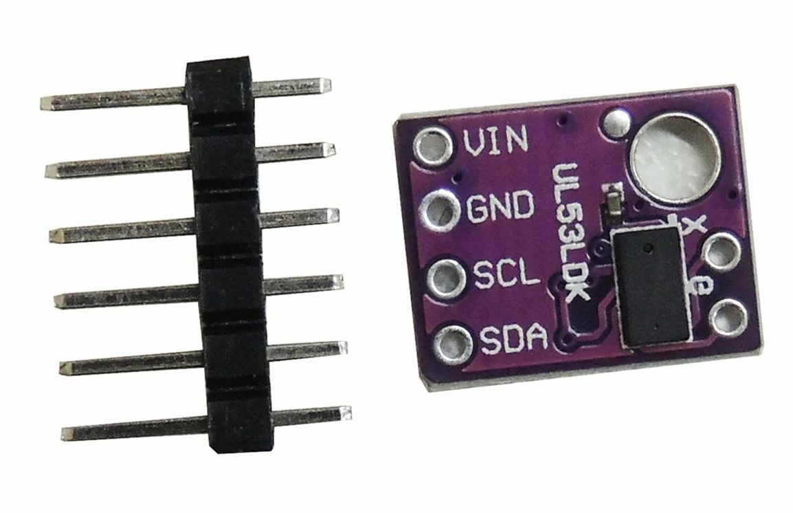
The sensor called VL53L0x is a time-of-flight ranging sensor from ST Semiconductors, whose datasheet is here. Applications of this sensor include (as stated) robotics, liquid level detection, and access control.
Its laser detects objects up to two (2) meters regardless of the reflectance, while being totally invisible to the human eye. Using the I2C scanner sketch, I determined its I2C address as 0x29. You also don’t have to worry about that, since addressing is handled for you by the sensor’s library.
Another note is regarding where to buy the components for this tutorial. I am in no way sponsored by Aliexpress, but I buy everything there. I live in Brazil, and it is easy and straightforward to get your Arduino stuff there.
Schematic diagram
The schematic diagram for our project is rather simple, as stated before, both the OLED and the distance sensor use I2C communication. So only four wires will suffice to connect both; these are +3.3V, GND, SDA, and SCL. Als,o as stated, power comes via USB-C C so no worries about that, we just use the 3.3V generated by the RP2040 Zero board.
I have assembled the prototype on an 830-point breadboard, but I am very sure it would fit in a 400-point one as well.
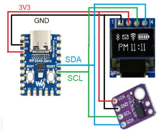
I2C’s SDA goes on pin 4 and SCL on pin 5 of the RP2040 Zero. I had to figure that out myself, since in the pinout diagram I made available above, the RP2040 has multiple possible sets of I2C pins. Then I had to test one by one, starting from I2C0 (because I knew it would be on I2C0, not I2C1) on pins 0 and 1. I was lucky I2C2 enough that I tested pins 4 and 5 second and already found them to be the ones.
Getting the Arduino IDE ready to be used
First of all, make sure you have the Arduino IDE 2.x.x installed on your computer. Then we will install support for the RP2040 Zero from Waveshare. To do that, you copy the URL below and paste it in “File > Preferences > Additional boards manager URLs”.
https://github.com/earlephilhower/arduino-pico/releases/download/4.0.2/package_rp2040_index.json
Then go to the Arduino IDE’s boards manager in “Tools > Board > Boards manager” and type “Waveshare”. Install the library for RP2040/RP2350. Next step, we will need to install two libraries in our Arduino IDE: “u8g2lib” for the OLED display and “VL53L0x by Pololu” for the distance sensor.
Go to “Sketch > Include library > Manage libraries” and type “u8g2”, install the one from Oliver. Now type “VL53L0x” and install the one by Pololu. You are now set to start coding, which we will do next.
Coding and functions
As stated at the beginning of the article, our goal is to implement a circuit that measures the distance from the sensor to an object. That is going to give us a value in millimeters, which will then be presented at the OLED screen with an update rate of 10Hz. That means the circuit will do its thing ten (10) times a second.
I have implemented non-blocking code, using the “millis()” function to keep track of time and act accordingly. This means that this code could execute many other things “simultaneously” (sort of), or at least very quickly. If one used “delay()” one of two things (or both) could happen:
- Display would not be updated properly
- The sensor would not be read properly and on time
Basically, what I did was to implement code that reads the distance and prints it to the display as it happens. Doing that 10 times a second. When not executing such a function, the processor is just looping freely through nothing. You can see the complete code below, even commented for ease of understanding.
#include <Arduino.h>
#include <U8g2lib.h>
#include <Wire.h>
#include <VL53L0X.h>


VL53L0X sensor;


U8G2_SSD1306_64X32_1F_F_HW_I2C u8g2(U8G2_R0, /* reset=*/ U8X8_PIN_NONE); // Configure our 64x32 pixels display


int distancemm; // varible for the distance from the VL53L0x sensor
long oldtime; // variable for keeping track of time


void setup() {
  u8g2.begin();

  Serial.begin(115200);


  sensor.setTimeout(500);
  if (!sensor.init())
  {
    Serial.println("Failed to detect and initialize sensor!");
    while (1) {}
  }


  // Start continuous back-to-back mode (take readings as
  // fast as possible).  To use continuous timed mode
  // instead, provide a desired inter-measurement period in
  // ms (e.g. sensor.startContinuous(100)).
  sensor.startContinuous(50);


}


// fonts https://github.com/olikraus/u8g2/wiki/fntlistall#4-pixel-height (I have picked two of them for this article)


void loop()
{

  if(millis() - oldtime > 100){ // Only does anything every 100ms
    oldtime= millis();


    distancemm= sensor.readRangeContinuousMillimeters();
    Serial.println(distancemm);

    u8g2.clearBuffer();          // clear the internal memory
    u8g2.setCursor(0, 24);
    u8g2.setFont(u8g2_font_t0_17_tn);  // choose a suitable font
    u8g2.print(distancemm);
    u8g2.setCursor(40, 24);
    u8g2.setFont(u8g2_font_9x18_mf);
    u8g2.print("mm");
    u8g2.sendBuffer();          // transfer internal memory to the display
  }

}
For some reason, I had to pick two different fonts for this project. One for the distance variable and the other for the “mm” text. I figure that if I used the font of the variable for the text, it would vanish from the screen. So the fixed “mm” text font is smaller (size 12) and the variable one is bigger (size 17).
Besides that, this display mandates that we first “clearBuffer”, tell it which text goes where, then “sendBuffer”. That is true for every iteration (every time we need to change text). The “print” function is responsible for sending our text or variable to the OLED memory.
Results
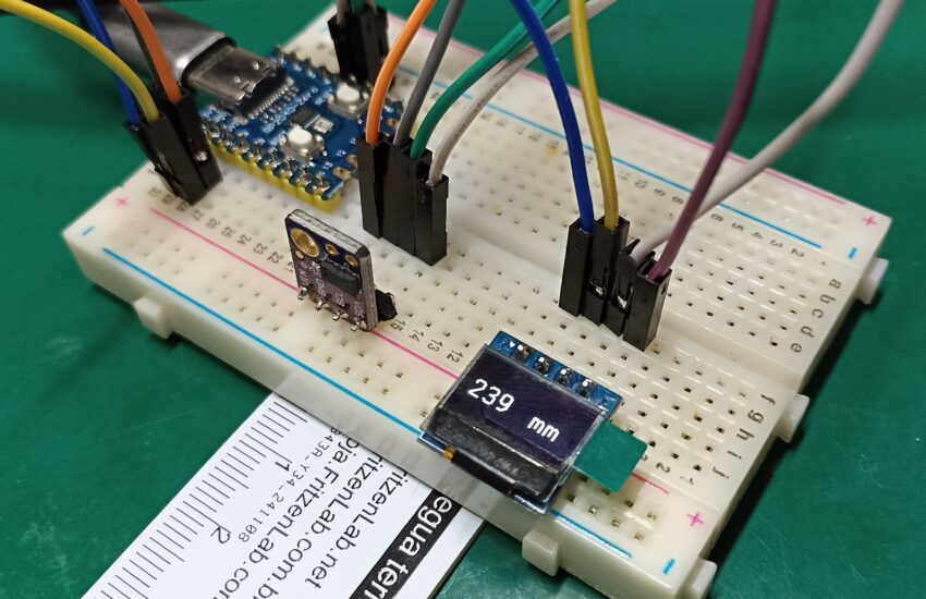
As you can see in the picture and video below, a distance is read every 100ms and printed in our small OLED. Fixed text “mm” does not bother or get bothered by anything around it. There is a “Serial.print” function to send data to the Arduino IDE serial monitor, for you to have a look at it and compare.
Video
Conclusions
If you look closely at the ruler under the breadboard, our measurement on the screen is not quite precise as it is. It may come down to calibration (most certainly), some exercise I will leave to you to implement. Tip: Just subtract a constant from the measured value.
Finally, as a closing thought, we have gone through everything one needs to replicate this measurement device at home, using virtually any Arduino. I have shown you the RP2040 pinout, OLED display, and VL53L0x sensor specs and usage. We have also walked you through configuring the Arduino IDE software to receive our board and libraries.
If you have any questions, please post in the comments section below. We will do our best to answer.