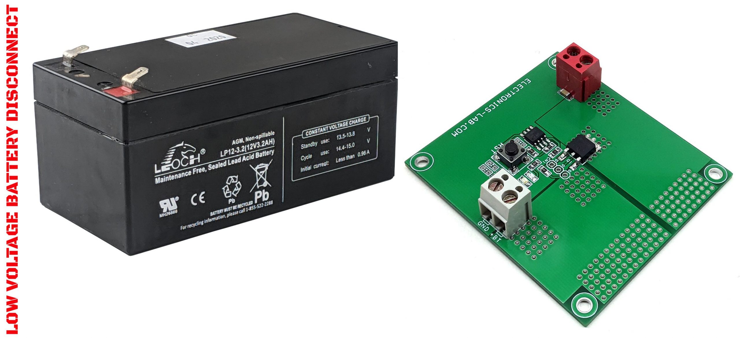
Low Voltage Lead Acid Battery Disconnect board – Prevents Deep Discharge Of 12V Lead Acid Battery
This project helps to optimize the 12V lead-acid (SLA) battery life as it prevents the battery from going into deep discharge. It is very important to disconnect the load before the battery enters into deep discharge as this may destroy or damage the battery cells.
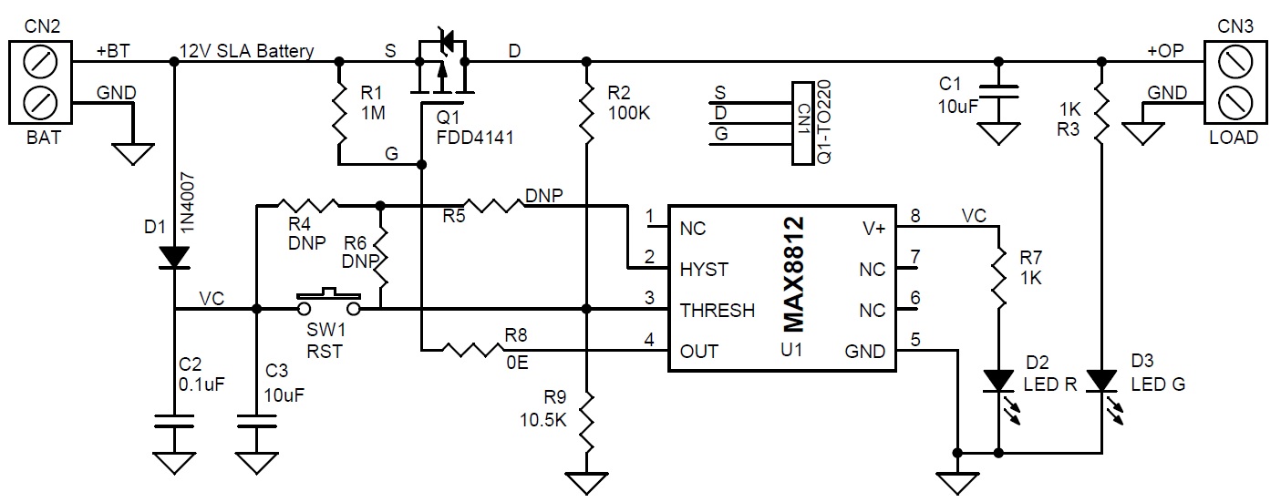
This project helps to optimize the 12V lead-acid (SLA) battery life as it prevents the battery from going into deep discharge. It is very important to disconnect the load before the battery enters into deep discharge as this may destroy or damage the battery cells. The circuit shown here turns off the load before the battery enters deep discharge and avoids a further (deep) discharge that can shorten the SLA battery life. Once the battery is recharged or replaced you need to push a reset switch to power ON the load. The predetermined load level is set to 12V, this voltage level is proportional to the battery voltage which is determined by resistor divider R2, and R9. Once the voltage falls below the setpoint (12V) it disconnects the load, the load-battery connection remains open until the system receives a manual reset command using tactile switch SW1.
The circuit drains 5uA + PWR LED D2 5mA, so the circuit can remain in that state for an extended period without causing a deep discharge of the battery. Users may not use LED D2 if not required. The circuit is capable to drive continuous load up to 5A and can provide more power with forced air cool to the MOSFET Q1. Connector CN1 is optional if the user wants to use TO220 MOSFET. The project is ideal for 1Ah to 10Ah 12V lead-acid batteries. Low ohm MOSFET is used to provide continuous maximum current output.
Features
- Input Supply (12V Lead Acid Battery)
- Continues Load up to 5Amps
- Deep Discharge Disconnect Voltage Level 12V
- Large size PCB thermal area provided for MOSFET for heat dissipation
- On-Board Tactile Switch for Reset the output
- LED D2 Indicates Battery Power
- LED D3 Indicated Load ON/OFF
- Screw Terminal CN2 Battery
- Screw Terminal CN1 Load
- PCB Dimensions 68.10 x 60.33 mm
Schematic
Parts List
| NO. | QNTY. | REF. | DESC. | MANUFACTURER | SUPPLIER | SUPPLIER PART NO |
|---|---|---|---|---|---|---|
| 1 | 1 | CN1 | Q1-TO220 DNP | |||
| 2 | 1 | CN2 | 2 PIN SCREW TERMINAL 5.08MM PITCH | PHOENIX | DIGIKEY | 277-1247-ND |
| 3 | 1 | CN3 | 2 PIN SCREW TERMINAL 5.08MM PITCH | PHOENIX | DIGIKEY | 277-1247-ND |
| 4 | 2 | C1,C3 | 10uF/16V SMD SIZE 1206 | MURATA/YAGEO | ||
| 5 | 1 | C2 | 0.1uF/50V SMD SIZE 0805 | MURATA/YAGEO | ||
| 6 | 1 | D1 | 1N4007 SMD | DIODE | DIGIKEY | S1MBDITR-ND |
| 7 | 1 | D2 | LED RED SIZE 0805 | OSRAM | DIGIKEY | 475-1415-1-ND |
| 8 | 1 | D3 | LED GREEN SMD SIZE 0805 | OSRAM | DIGIKEY | 475-1410-2-ND |
| 9 | 1 | Q1 | FDD4141 MOSFET | ON SEMI | MOUSER | 512-FDD4141 |
| 10 | 1 | R1 | 1M 5% SMD SIZE 0805 | MURATA/YAGEO | ||
| 11 | 1 | R2 | 100K 1% SMD SIZE 0805 | MURATA/YAGEO | ||
| 12 | 2 | R3,R7 | 1K 5% SMD SIZE 0805 | MURATA/YAGEO | ||
| 13 | 3 | R4,R5,R6 | DNP | |||
| 14 | 1 | R8 | 0E SMD SIZE 0805 | MURATA/YAGEO | ||
| 15 | 1 | R9 | 10.5K 1% SMD SIZE 0805 | MURATA/YAGEO | ||
| 16 | 1 | SW1 | 4 PIN TACTILE SWITCH | C&K | DIGIKEY | CKN9085TR-ND |
| 17 | 1 | U1 | MAX8212 | MAXIM | DIGIKEY | MAX8212ESA+-ND |
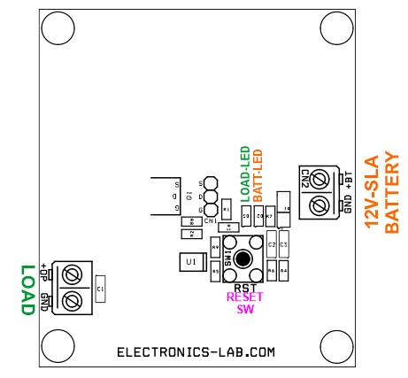
Connections
Gerber View
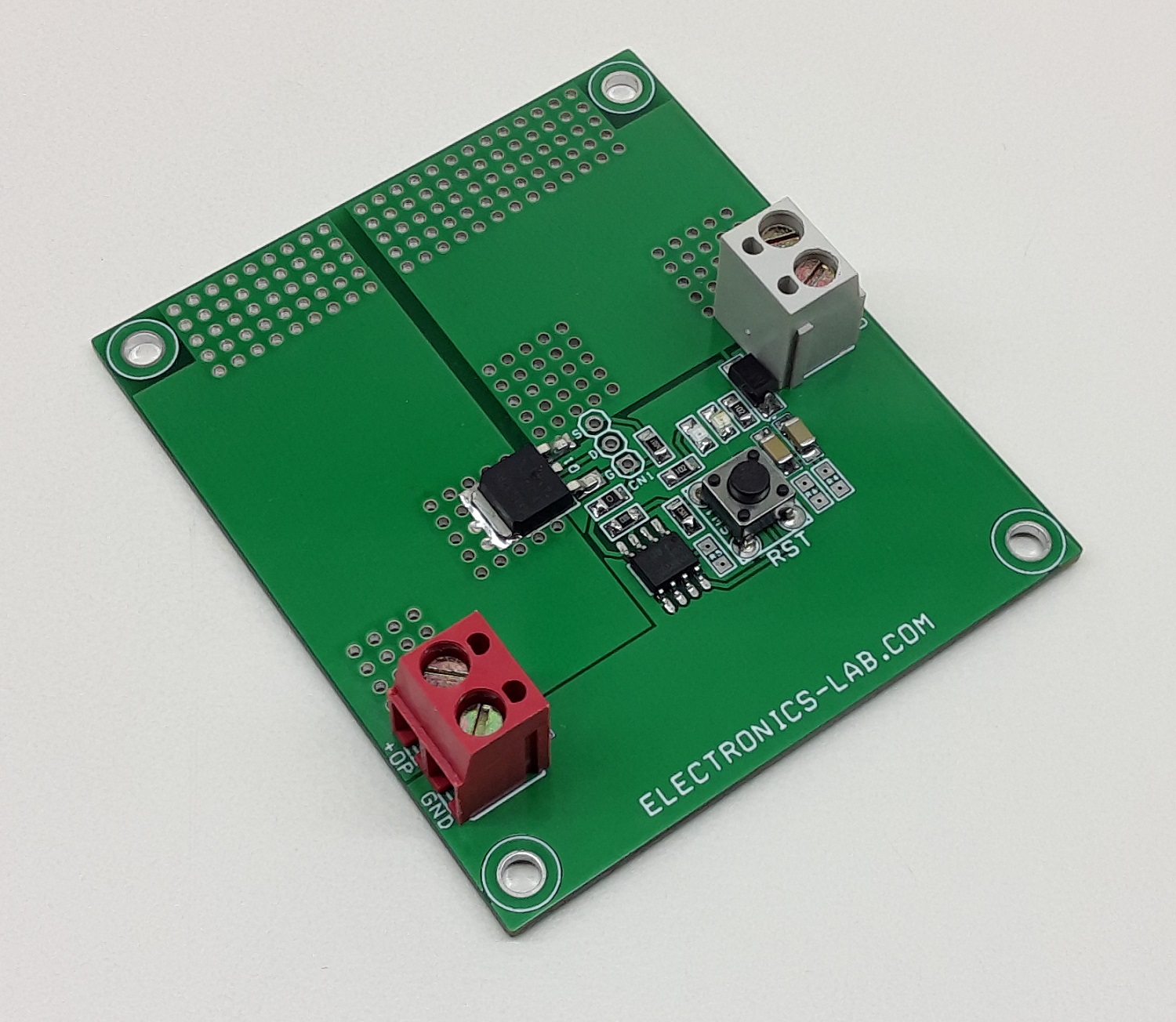
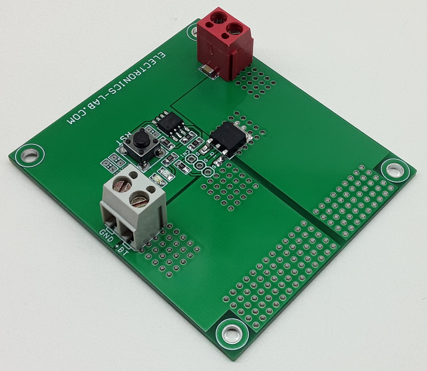
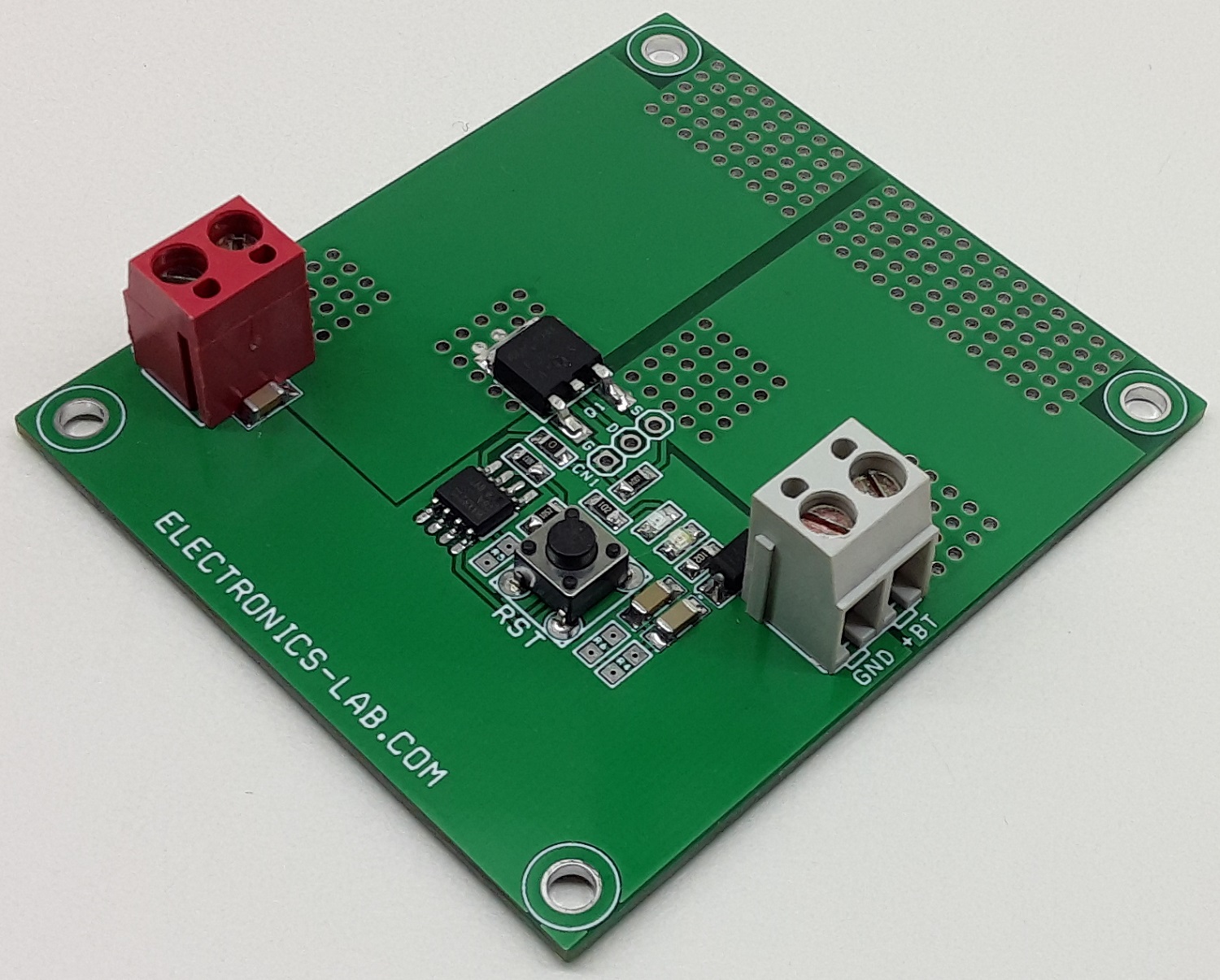
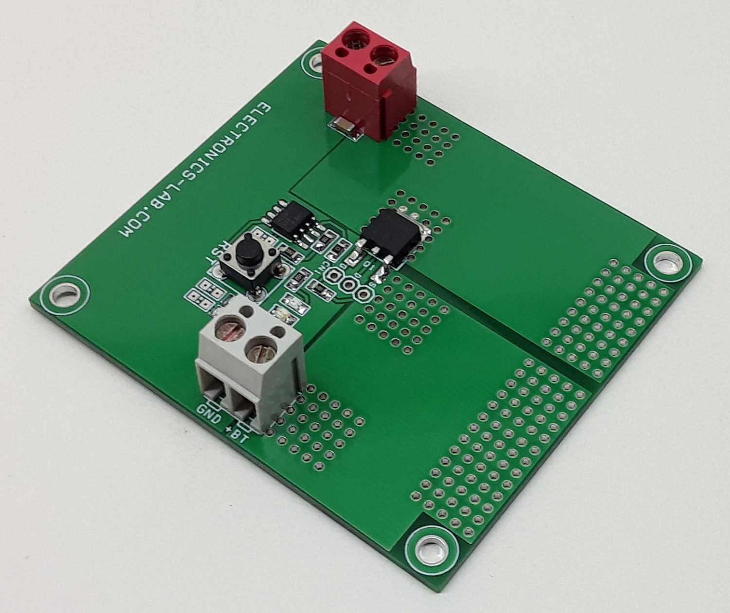
Photos
Video
Doesn’t the current through R2+R9 exceed the advertised quiescent current of 5uA : 12/(R2+R9) ~ 100 uA