Lux Meter Module
- Rajkumar Sharma
- 18.569 Views
- easy
- Tested
- SKU: EL46874
- Quote Now
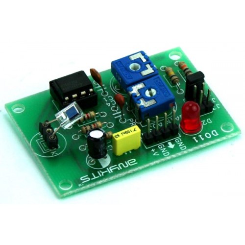
LUX Meter project has been design to measure the illumination. Illumination is luminous flux falling on surface area of photo diode. This illumination converted to corresponding voltage using Op-Amp circuit.
Specifications
- Supply 9 VDC PP3 Battery @ 20 mA
- Onboard Photo Diode
- Onboard preset for calibration
- Range selection via jumper 10mV/LUX, 1mV/LUX, 0.1mV/LUX
- Interfacing is via berg connector
- Power-On LED indicator
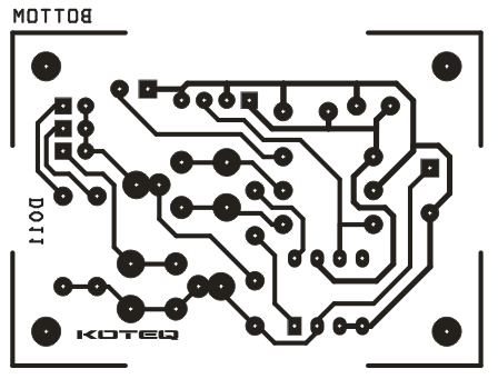
- Four mounting holes of 3.2 mm each
- PCB dimensions 53 mm x 38 mm
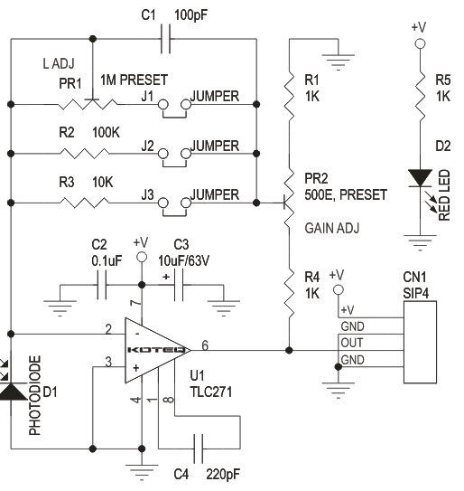
The project is designed around Texas instrument Op-Amp TLC271 which can operate from single supply with low bias current, here op-amp act as current to voltage converter. 5000 LUX (approx) can be measure with a voltmeter having 5V range. Meter is not provided.
Calibration
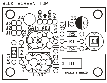
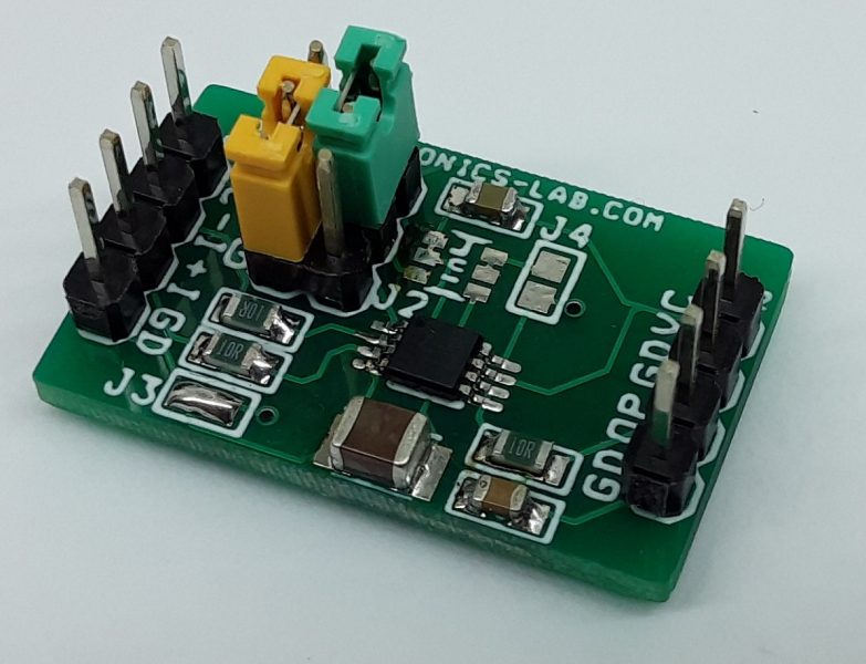
- J1 Jumper : 10mV/Lux
- J2 Jumper : 1mV/Lux
- J3 Jumper : 0.1mV/LUX
- PR2 Preset : To Calibrate the meter
- PR1 Preset : Fine Gain adjustment for 10mV/Lux
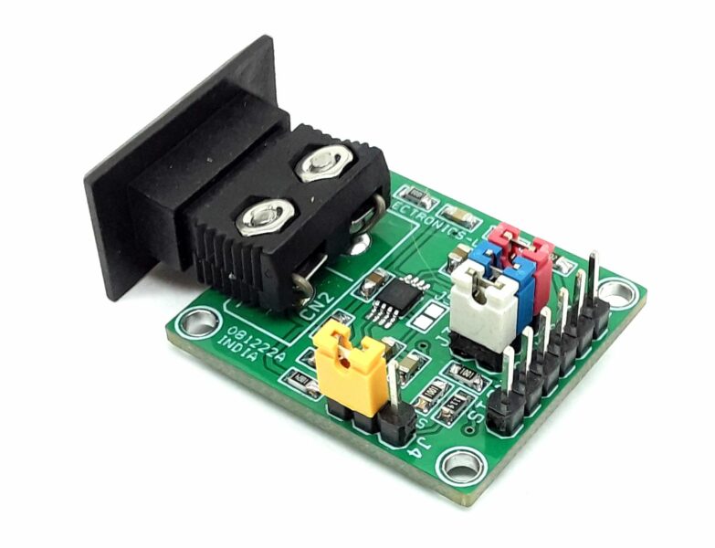
- CN1 Connector : Supply 9 VDC (PP3 9V DC Battery Ideal) and Output Voltage
- D2 LED : Power Indicator
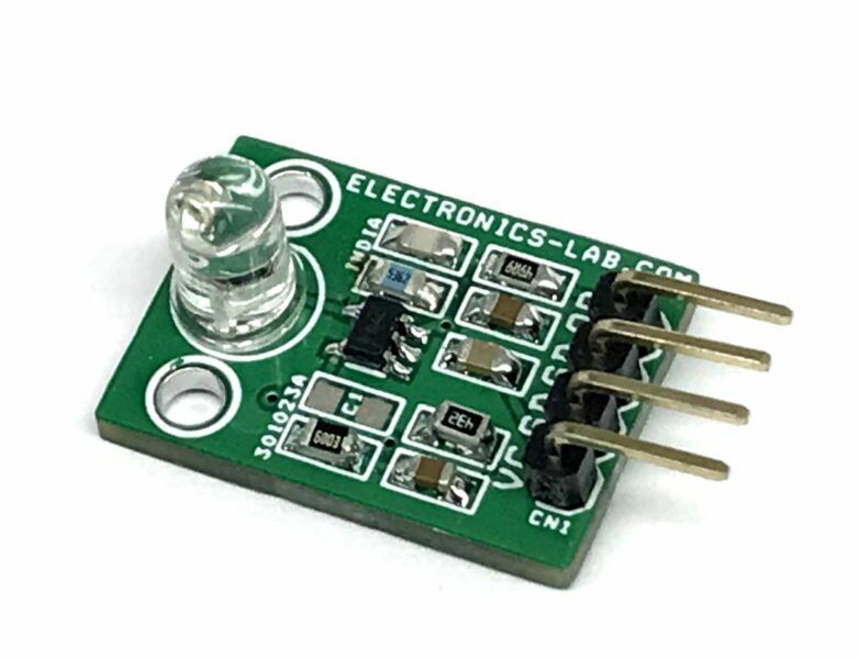
- D1 LED : Photo Diode (Sensor)
Standard incandescent 100W lamp should be used for approximation calibration. To make Calibration select the 1mV/Lux J2 Jumper, move the preset full in CCW. Connect the accurate voltmeter having range of 5V. Adjust the distance between the photo diode and Lamp so that voltmeter reads 0.38V0. At this point, illumination on photodiode surface is about 100 Lux (aprox). And then adjust the PR2 so that voltmeter reads 1V. Calibration has now been complete. This project is based on Hamamatsu Photo Diode Application
Schematic
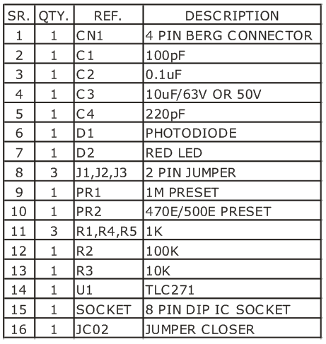
Parts List




What is the output of this circuit?
Or in other words, how should the output data of this circuit be read?
Is it possible to send the output value to a micro or arduino to display the result numerically for the user?
The output is an analog voltage proportional to the light intensity hitting the sensor. For example, 5000Lux will have an approximate output of 5V. You can convert this to a digital signal to feed to an MCU or Arduino or connect to the analog port of the Arduino for further processing. Be sure to check the analog port input voltage limits.