Smart Dual Coil Latching Relay Driver – Bistable Relay Module
This Smart Dual Coil latching Relay board can control the ON/OFF power of a device by applying a short voltage pulse to input 1 and input 2. This project is useful in low power applications since the coil is not powered all the time and only requires a short voltage pulse.
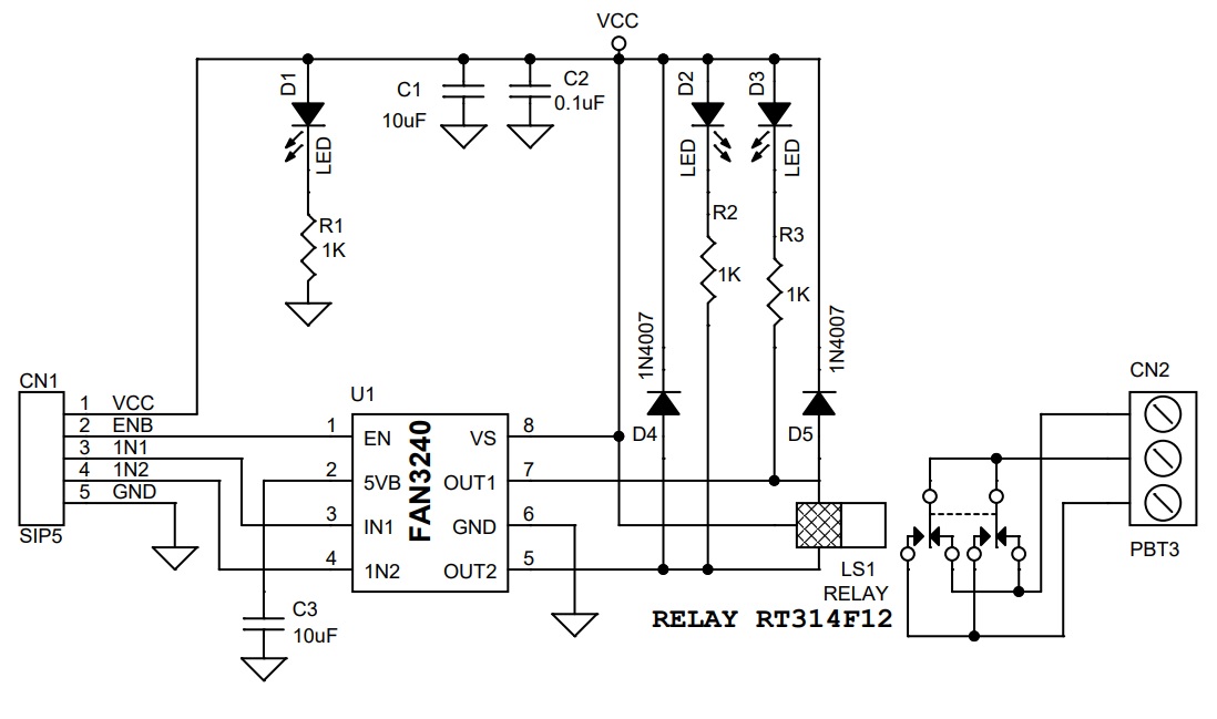
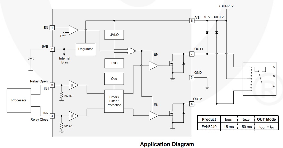
This Smart Dual Coil latching Relay board can control the ON/OFF power of a device by applying a short voltage pulse to input 1 and input 2. This project is useful in low power applications since the coil is not powered all the time and only requires a short voltage pulse. The relay coil remains in that position even if the power is disconnected. The project is built using FAN3240 chips from ONSEMI. This chip includes dual high current relay drivers designed to drive dual-coil polarized latching relays that connect and disconnect power in smart electronic meters and solar inverter applications. The IC includes auto thermal shutdown and a filter/timer block is there to prevent inadvertent switching from noisy input signals by providing input-pulse qualification (tQUAL) and maximum output pulse width limit (tMAX). Polarized, bi-stable, latching relays are utilized in many kinds of electronics equipment and diverse applications. These relays usually employ two coils, one to move the relay contacts(s) from open to close position and another coil to move the contacts(s) from close to open position. To facilitate mechanical movement, the relay coils need to be energized for a specific time interval. Once the contact(s) have changed position, the voltage should be removed from the winding of the relay. As shown in the schematic below, a dual-coil relay is connected to its supply rail at the center point of the two relay windings. Each winding can be energized by the switches connected to the relay coils out-1 and output-2. Diodes D4 and D5 are used as clamping diodes. Operation is very simple, enable PINs need to be high, apply minimum 15ms trigger voltage to input 1, this will provide 150ms pulse to relay coil -1 and coil moves contact(s) open to close, and when 15ms pulse is applied to input 2, coil-2 energized for 150ms and moves the contact(s) from close to open. Capacitor C3 is a filter capacitor for the internal 5V regulator of the chip.
Features
- Input Supply 12V DC
- Maximum Power Consumption Continues 5mA, Maximum 40mA when Relay is triggered for Short Time
- Accurate Input Qualification Time 15ms with Output Pulse Width Limit 150ms
- TTL Input Threshold, Enable, Input1, and Input 2 (High=5V – Low=0V)
- Minimum Input Pulse Width 15ms (The minimum input pulse width recognized as a valid input command) T-QUAL
- Maximum Output Pulse Width 150ms. Output pulses are terminated after this time interval even if the input pulse is longer or held in a high state continuously, T-Max
- Internal Thermal Shutdown Protection
- PCB Dimensions 37.15 x 31.27 mm
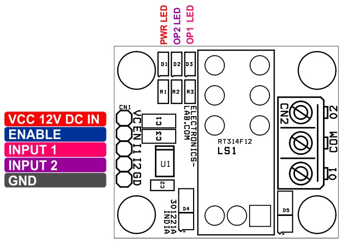
Connector CN
- Pin1: VCC 12V DC @ 40mA
- Pin2: Enable/disable pin allows shutdown of both channels (Enable=High Voltage – 5V TTL Level)
- Pin3: Input 1 to Set the Output (TTL)
- Pin4: input 2 to Reset the Output (TTL)
- Pin5: GND
Connector CN2: Relay Output Power ON/OFF Connections
- D1 LED: Power LED
- D2 LED: Output 2 Indicator
- D3 LED: Output 1 Indicator
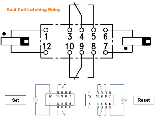
What is Latching Relay/Dual Coil Relay
Latching relays are commonly used in low power consumption or high-temperature applications where applying coil power for a long time cannot be afforded due to power consumption or self-heating of the coil. Instead of a continuous voltage applied to the coil, they are operated with short voltage pulses instead. Latching relays change contact position when a coil voltage is applied and remain in that position even if the voltage is disconnected. (It is common to use the term SET for operating a latching relay). To reset a latching relay another voltage pulse needs to be applied.
The FAN3240 includes dual high-current relay drivers designed to drive dual-coil polarized latching relays that connect and disconnect power in smart electronic meters and solar inverter applications. The output of the FAN3240 is rated for operation with supply rails from 8 V to 60 V. The filter/timer block prevents inadvertent switching from noisy input signals by providing input-pulse qualification (tQUAL) and maximum output pulse width limit (tMAX). The parameters are factory adjustable and additional configurations are available. XOR input protection is also provided so that both outputs are prevented from being on at the same time. The under-Voltage Lockout (UVLO) function disables the outputs until the supply voltage is within the operating range. The FAN3240 has two separate driver channels with non-inverting logic. One enable/disable pin allows shutdown of both channels, independent of the input signals. Internal thermal shutdown function is provided for thermal protection.
Schematic
Parts List
| NO | QNTY. | REF. | DESC. | MANUFACTURER | SUPPLIER | PART NO |
|---|---|---|---|---|---|---|
| 1 | 1 | CN1 | 5 PIN MALE HEADER PITCH 2.54MM | WURTH | DIGIKEY | 732-5318-ND |
| 2 | 1 | CN2 | 3 PIN SCREW TERMINAL | PHOENIX | DIGIKEY | 277-1248-ND |
| 3 | 2 | C1,C3 | 10uF/25V SMD SIZE 1206 | MURATA/YAGEO | DIGIKEY | |
| 4 | 1 | C2 | 0.1uF/25V SMD SIZE 0805 | MURATA/YAGEO | DIGIKEY | |
| 5 | 3 | D1,D2,D3 | LED SMD SIZE 0805/SELECT DIFFERENT COLOR | LITE ON INC | DIGIKEY | 160-1427-1-ND |
| 6 | 2 | D4,D5 | 1N4007 | SMC DIODE | DIGIKEY | 1655-1N4007FLCT-ND |
| 7 | 1 | LS1 | RELAY RT314F12 | TE CONNECTIVITY | DIGIKEY | PB963-ND or Z4396-ND |
| 1 | LS1 | or RELAY G5RL-K1-E-DC12 | OMRON | MOUSER | G5RL-K1-E-DC12 |
|
| 8 | 3 | R1,R2,R3 | 1K 5% SMD SIZE 0805 | MURATA/YAGEO | DIGIKEY | |
| 9 | 1 | U1 | FAN3240TMX SOIC8 | ON SEMI | ELEMENT14 | 3003952 |
Connections
Operation Diagram
Application Diagram
Gerber View
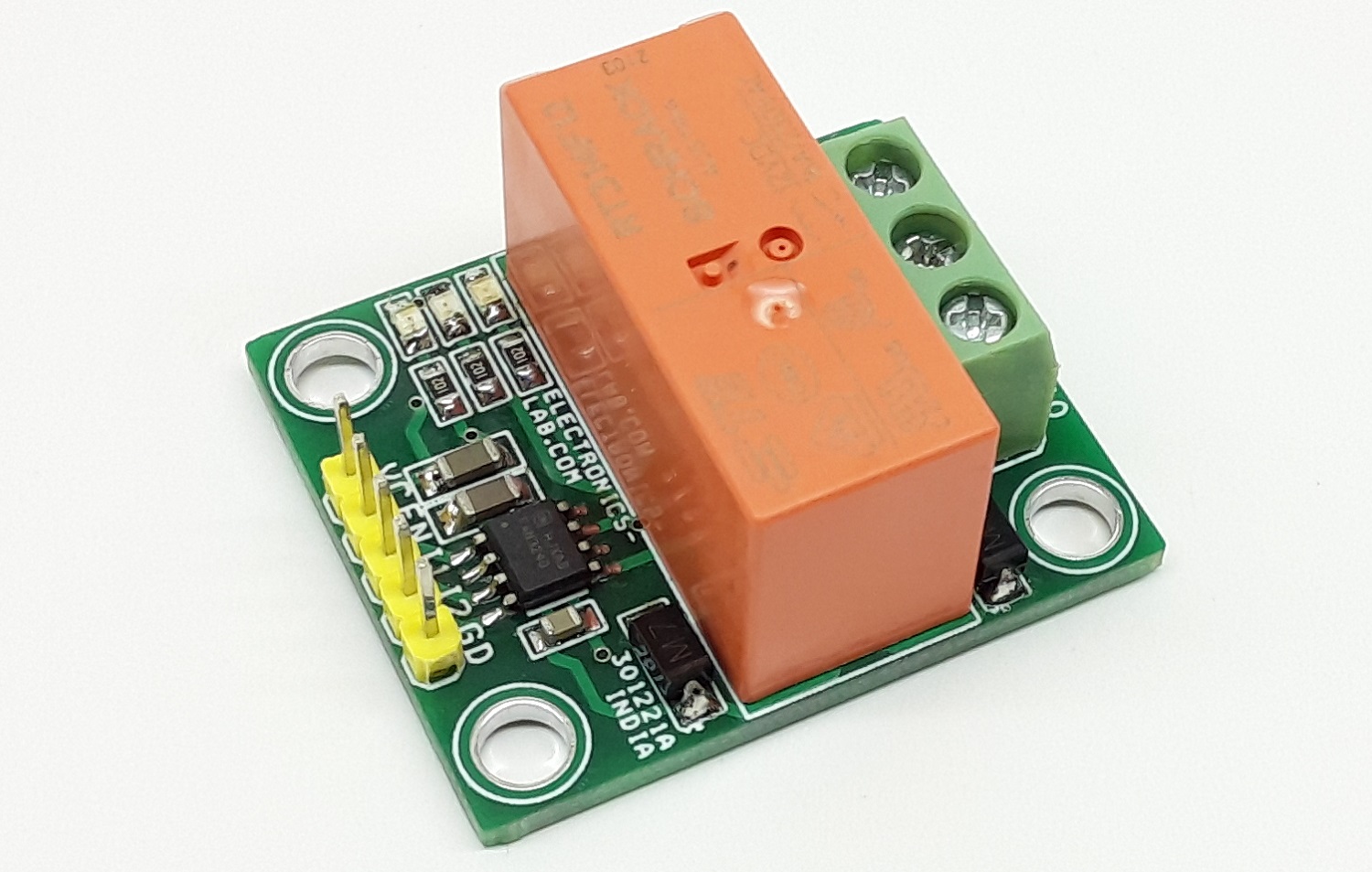
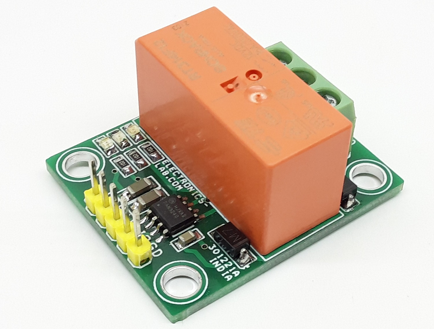
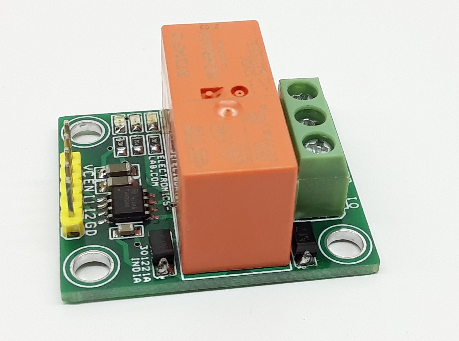
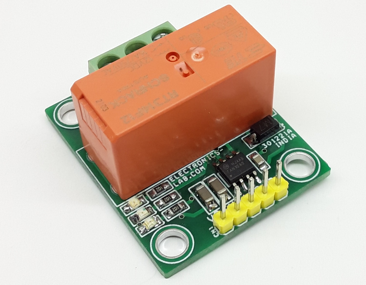
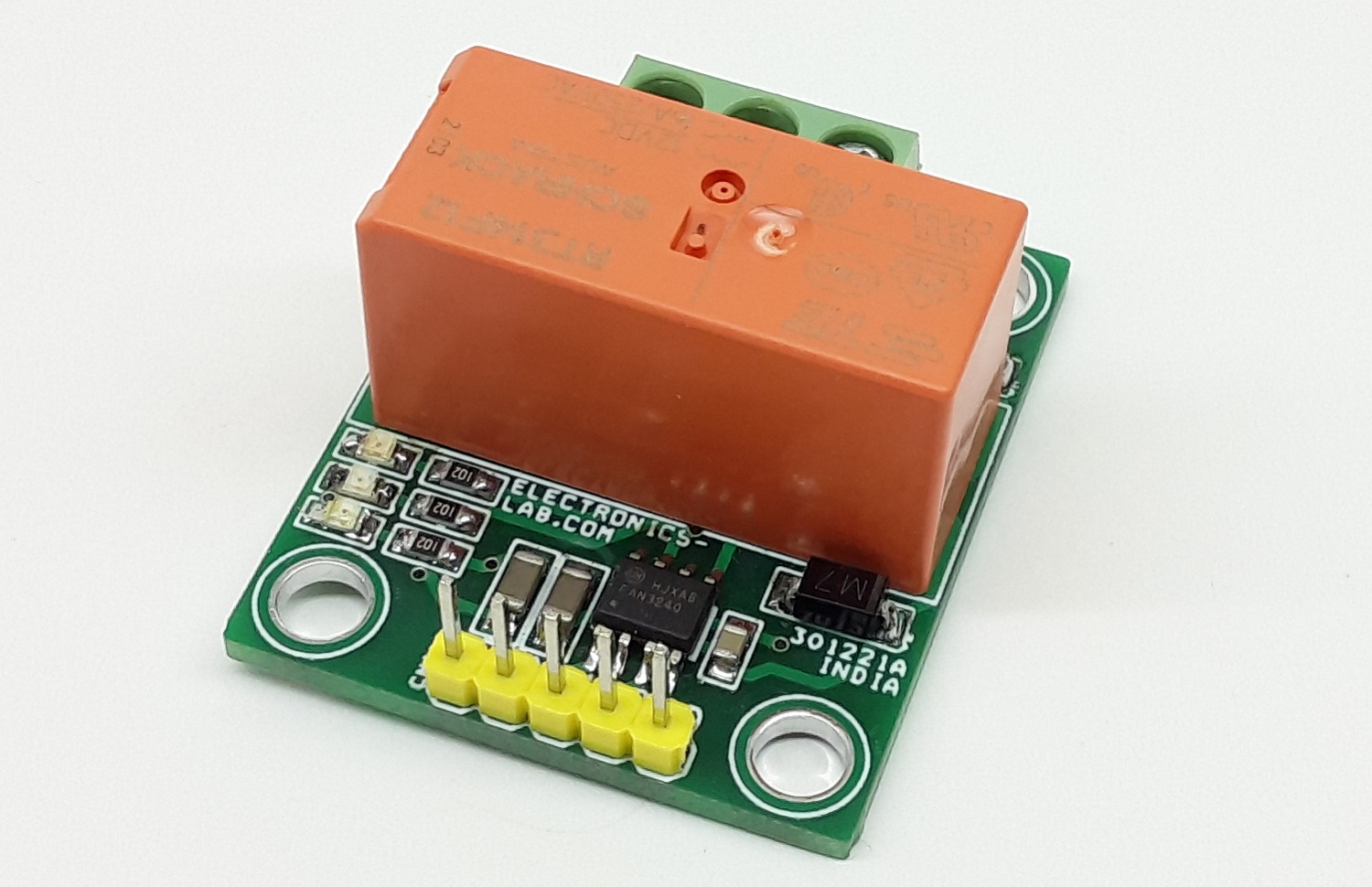
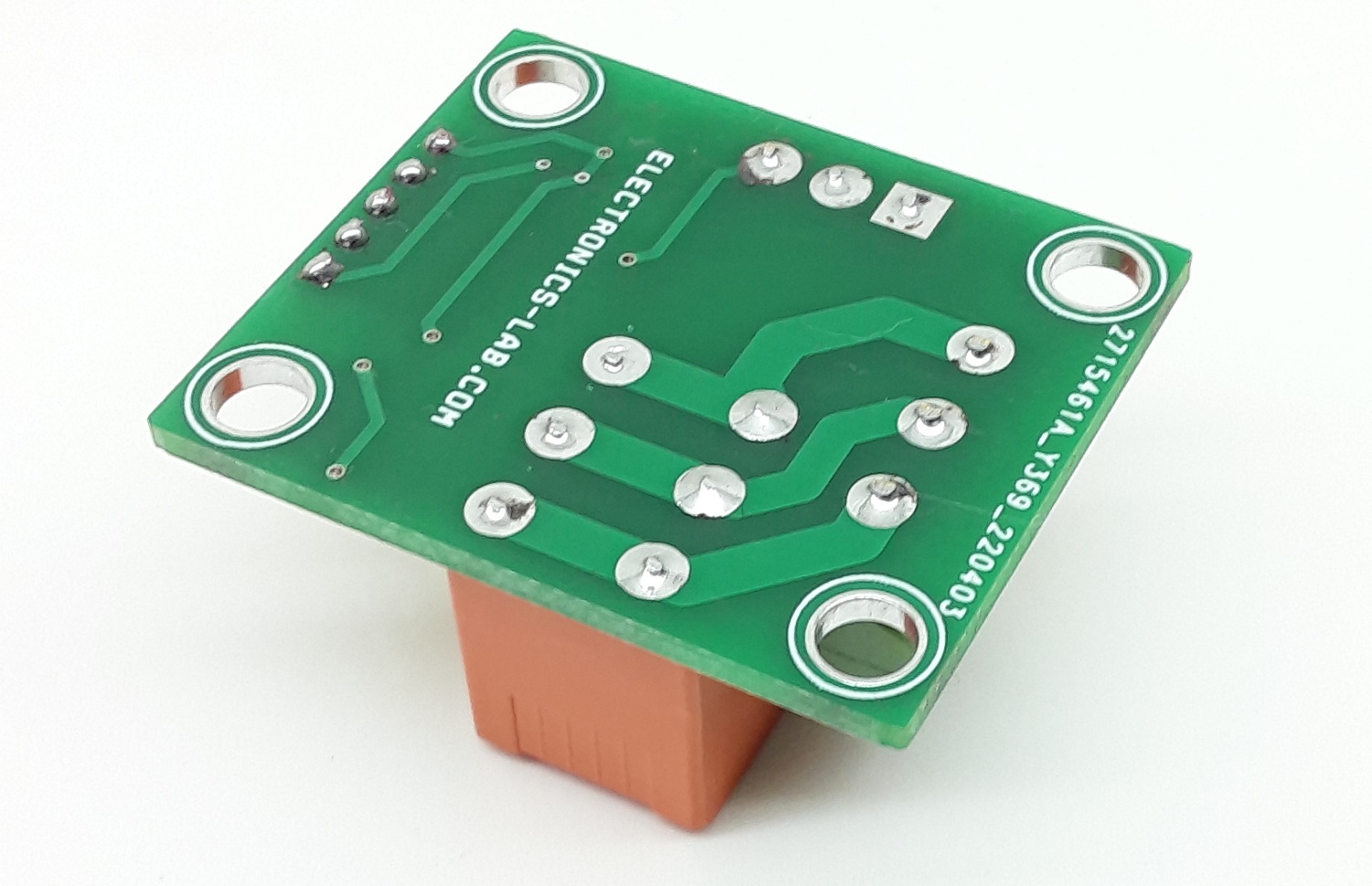
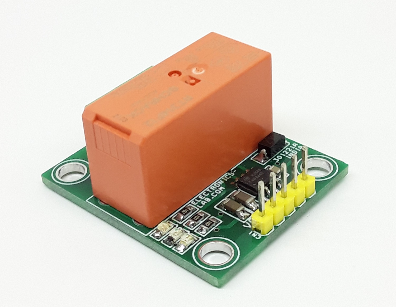
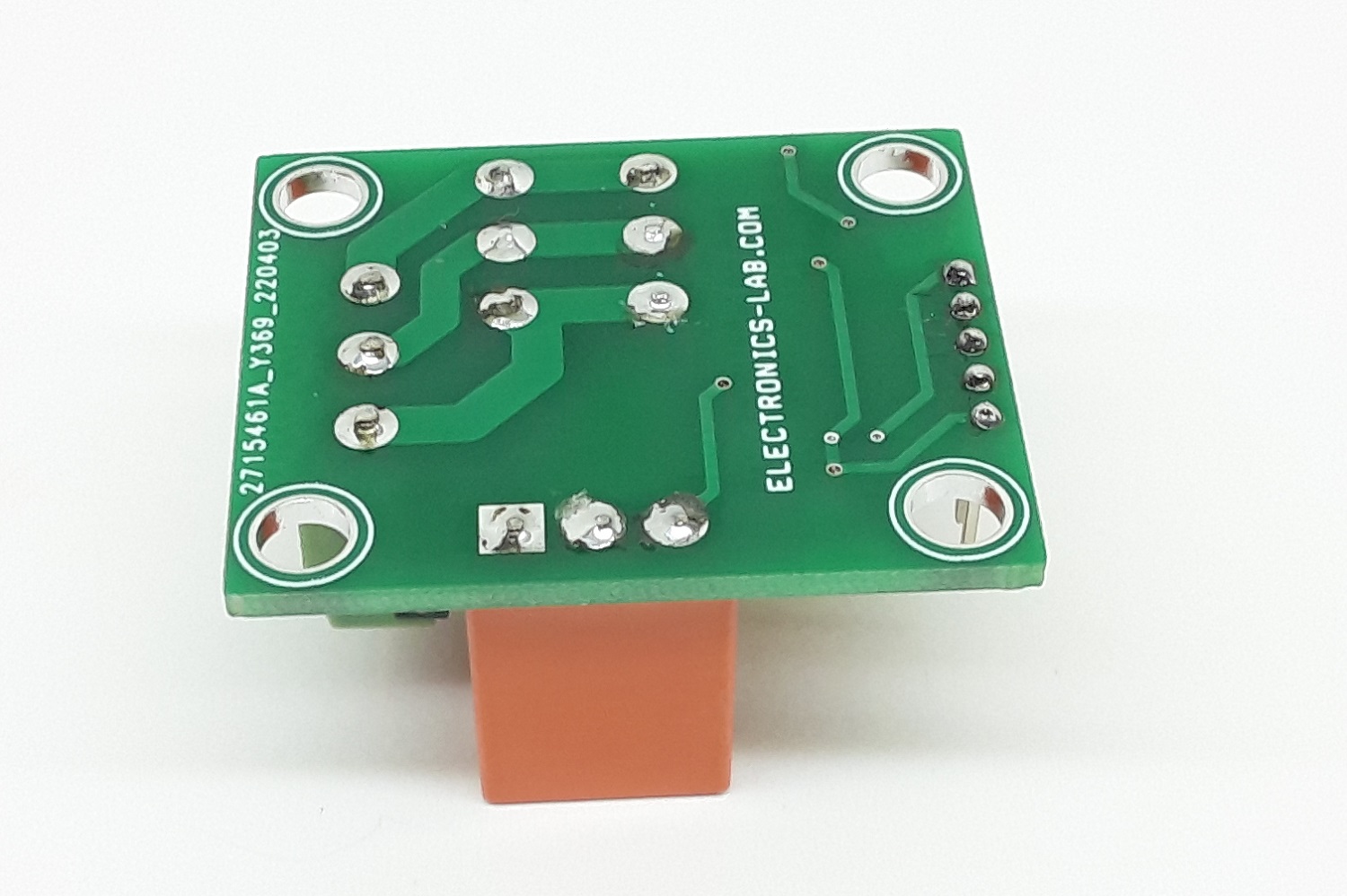
Photos
Video