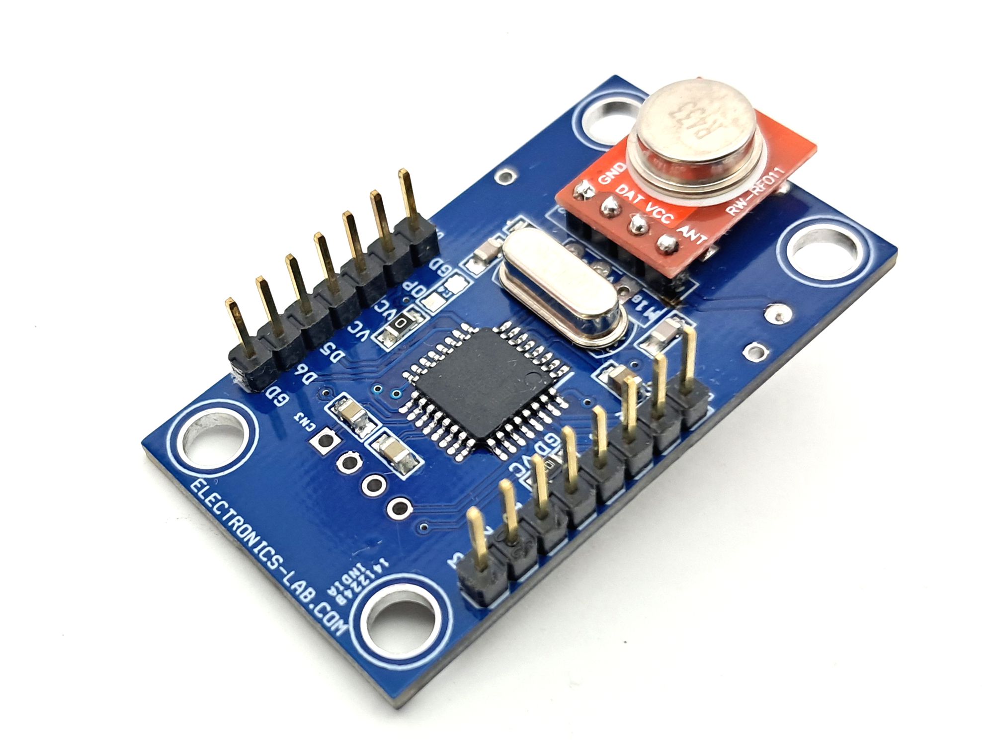
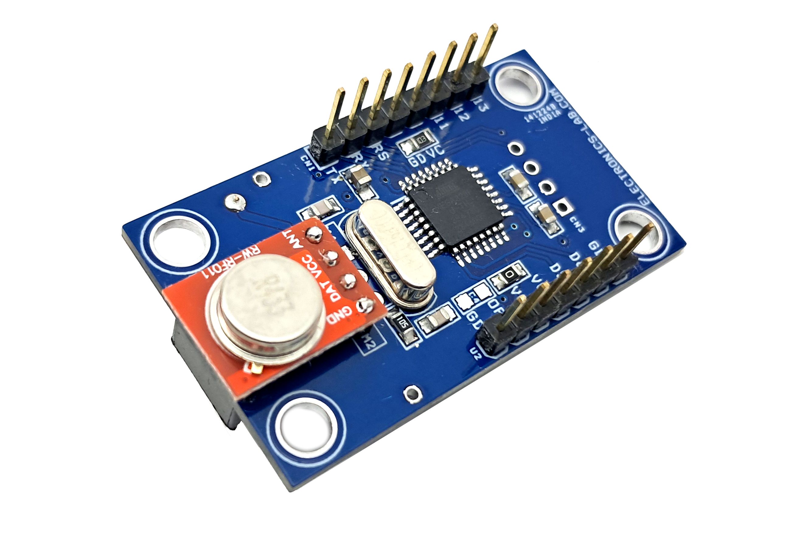
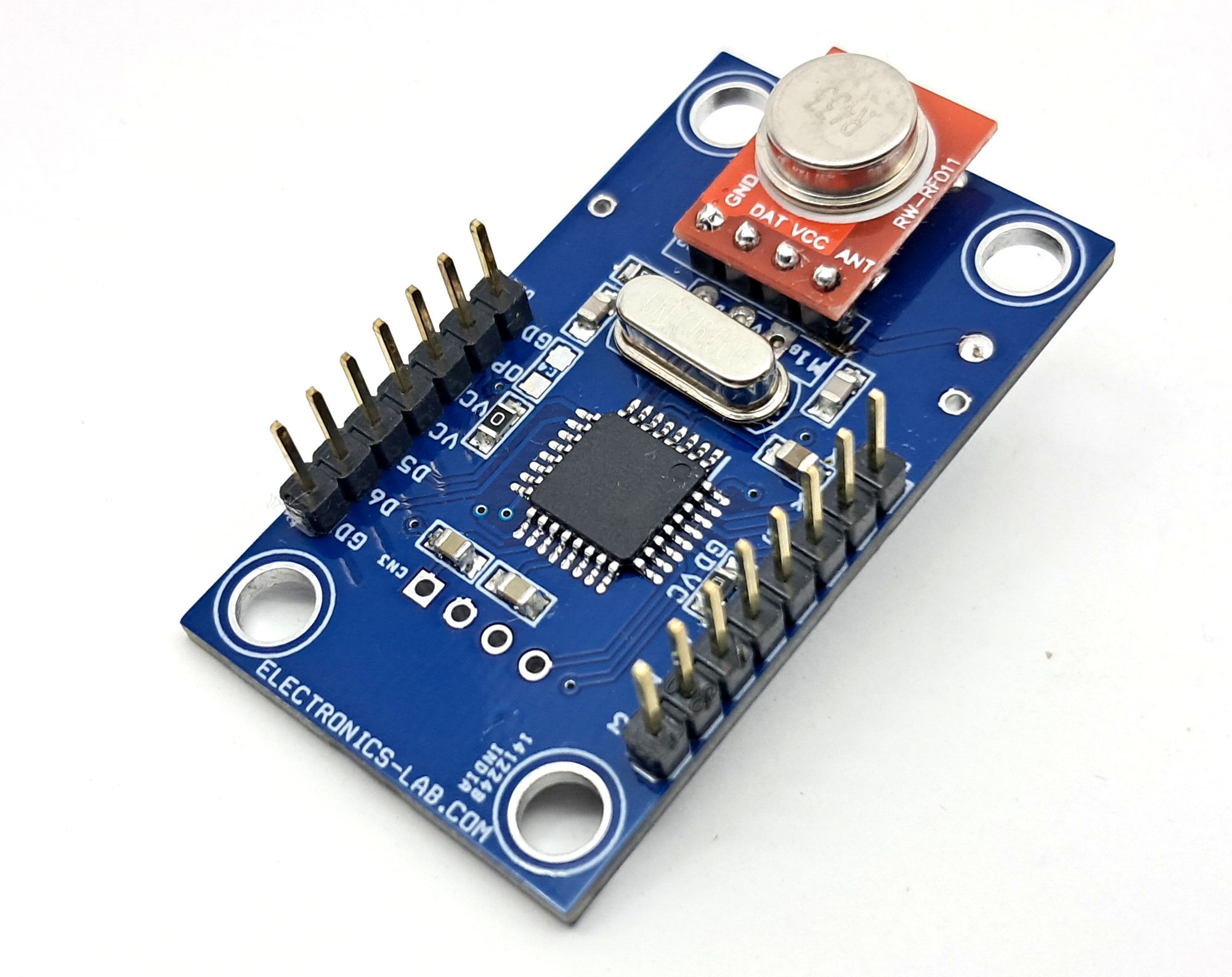
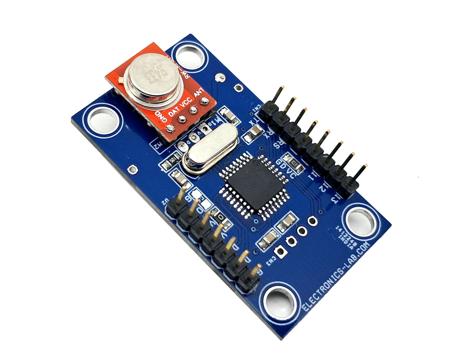
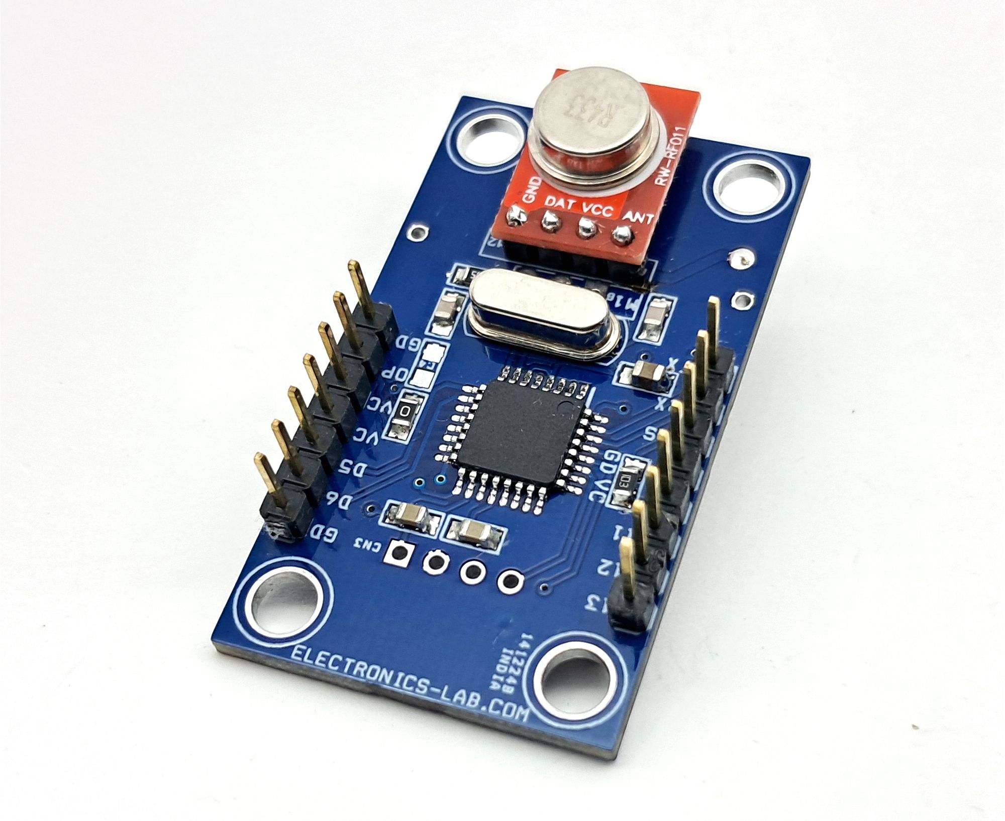
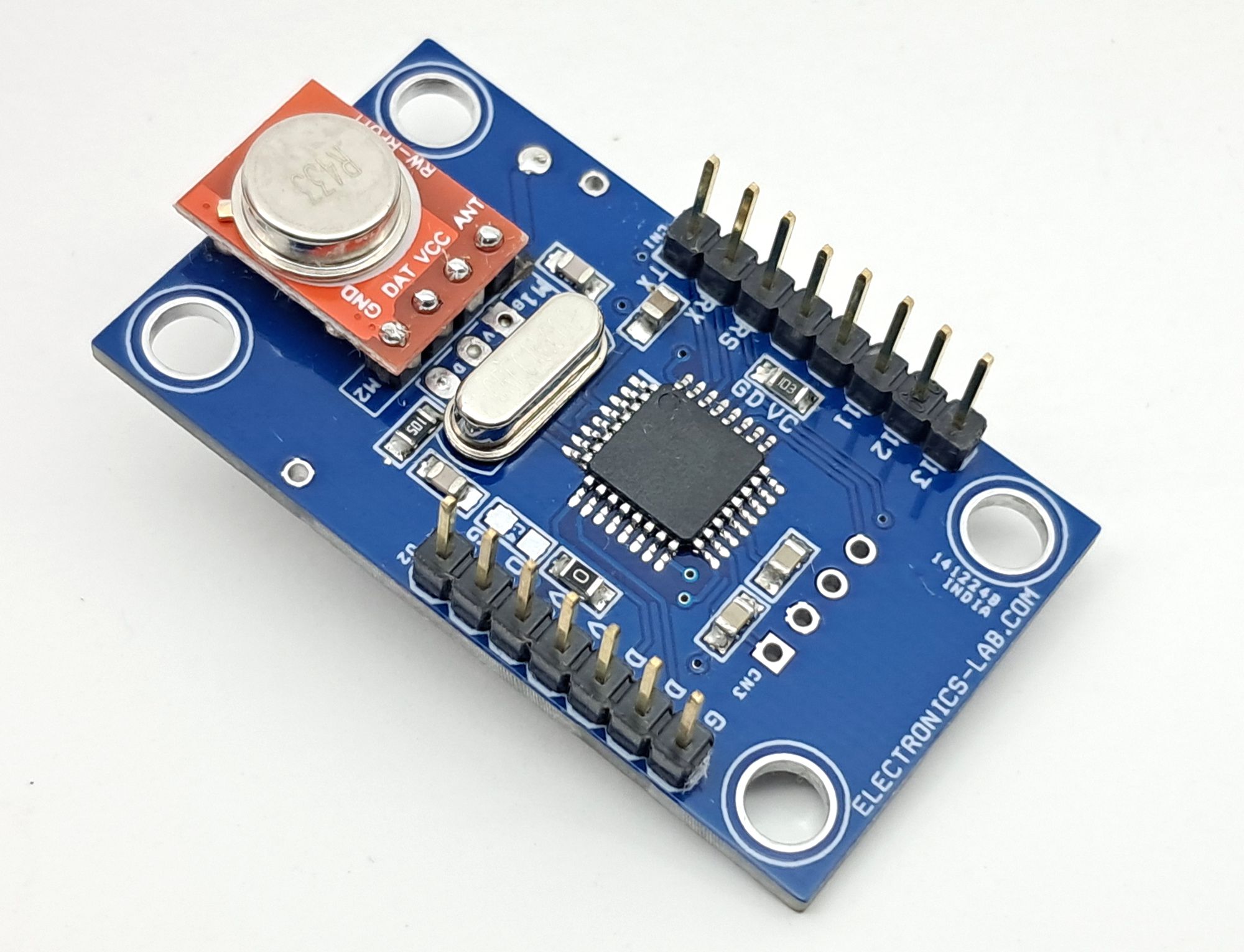
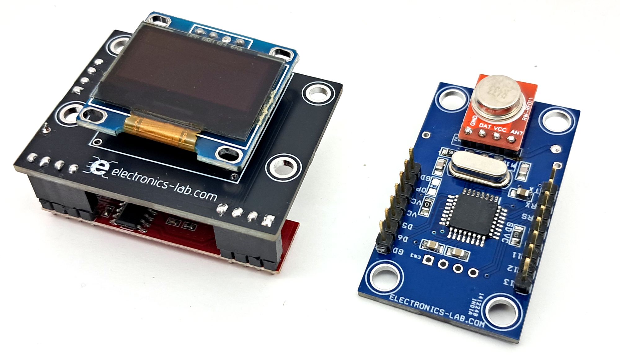
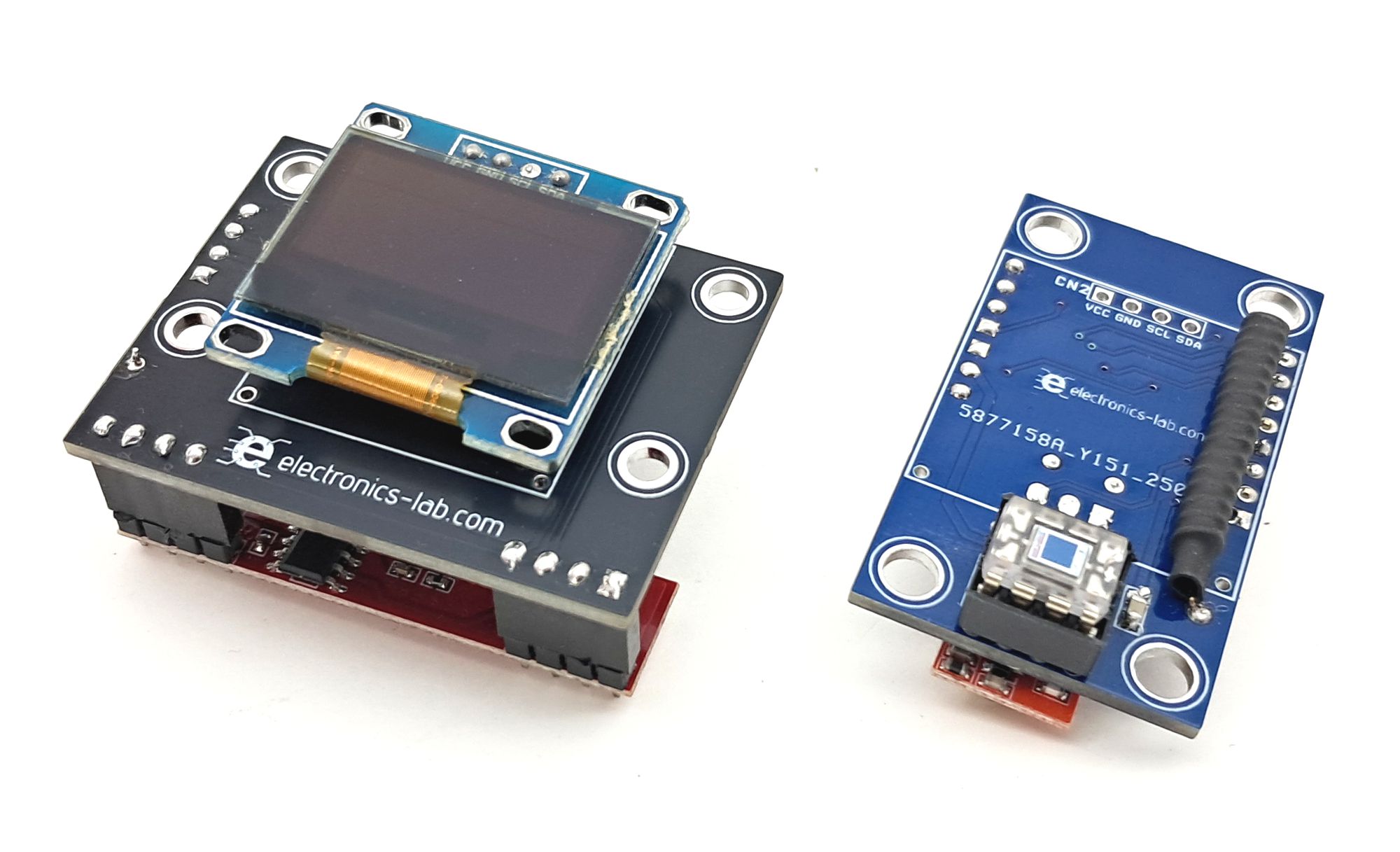
Wireless Light Level Monitor – Transmitter Unit
Wireless Light Monitor: OPT101 sensor, ATMEGA328, and 433MHz RF. Displays 0-100% light on a 0.96" OLED.
This project allows users to wirelessly monitor light levels on a compact 0.96-inch OLED display. The light intensity is measured using the OPT101 photo sensor IC, which produces an output voltage proportional to the amount of light it receives. The output voltage ranges from 0.2 to 4.7 volts, providing a reliable indication of the ambient light level. The voltage output from the OPT101 sensor is then monitored by the Analog-to-Digital Converter (ADC) of the ATMEGA328 microcontroller. The microcontroller processes the data and transmits it wirelessly through an RF 433 MHz module. On the receiving end, the data is received and displayed on the OLED display, showing the light level as a percentage value ranging from 0 to 100%. This innovative system enables users to remotely monitor and track changes in light levels, making it a useful tool for various applications.
Main Components
- ATMEGA328 Microcontroller
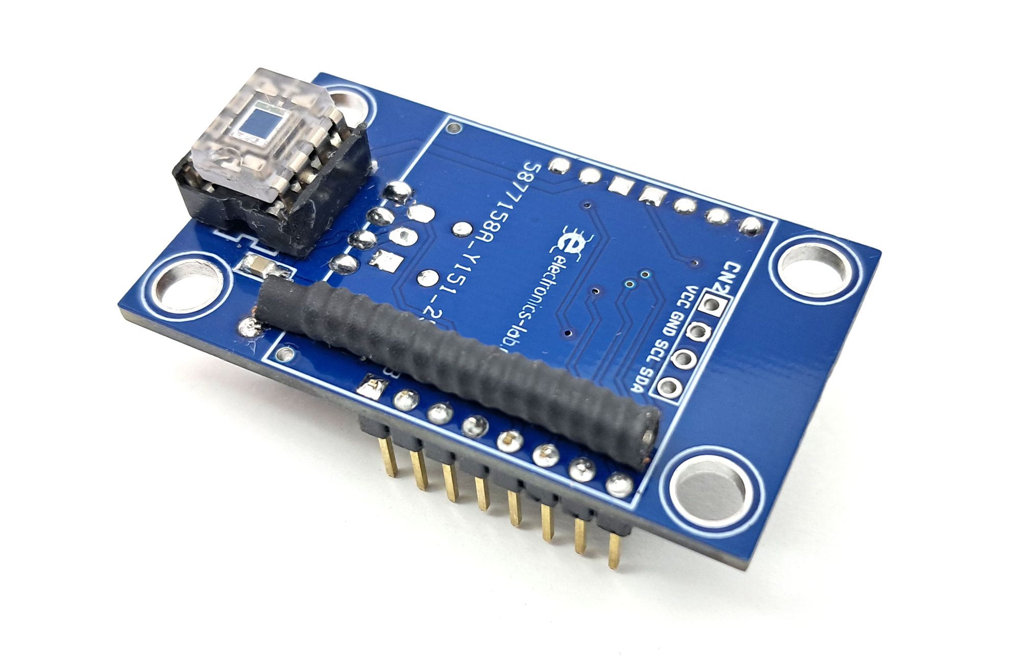
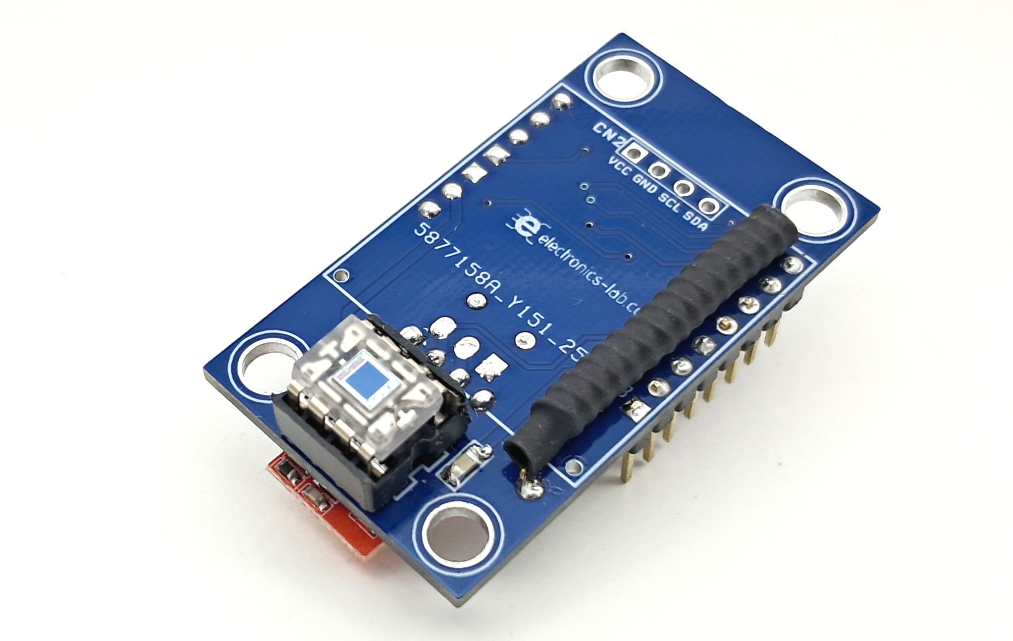
- OPT101 Photo sensor IC
- 433 MHz ASK RF Transmitter module
- Related components
Features
- Power Supply 5V DC
- On Board Light Sensor OPT101
- On board RF Transmitter Unit
- 4 x 4 mm Mounting Holes
- PCB Dimensions 46.67 x 26.83 mm
Arduino Code & Programming
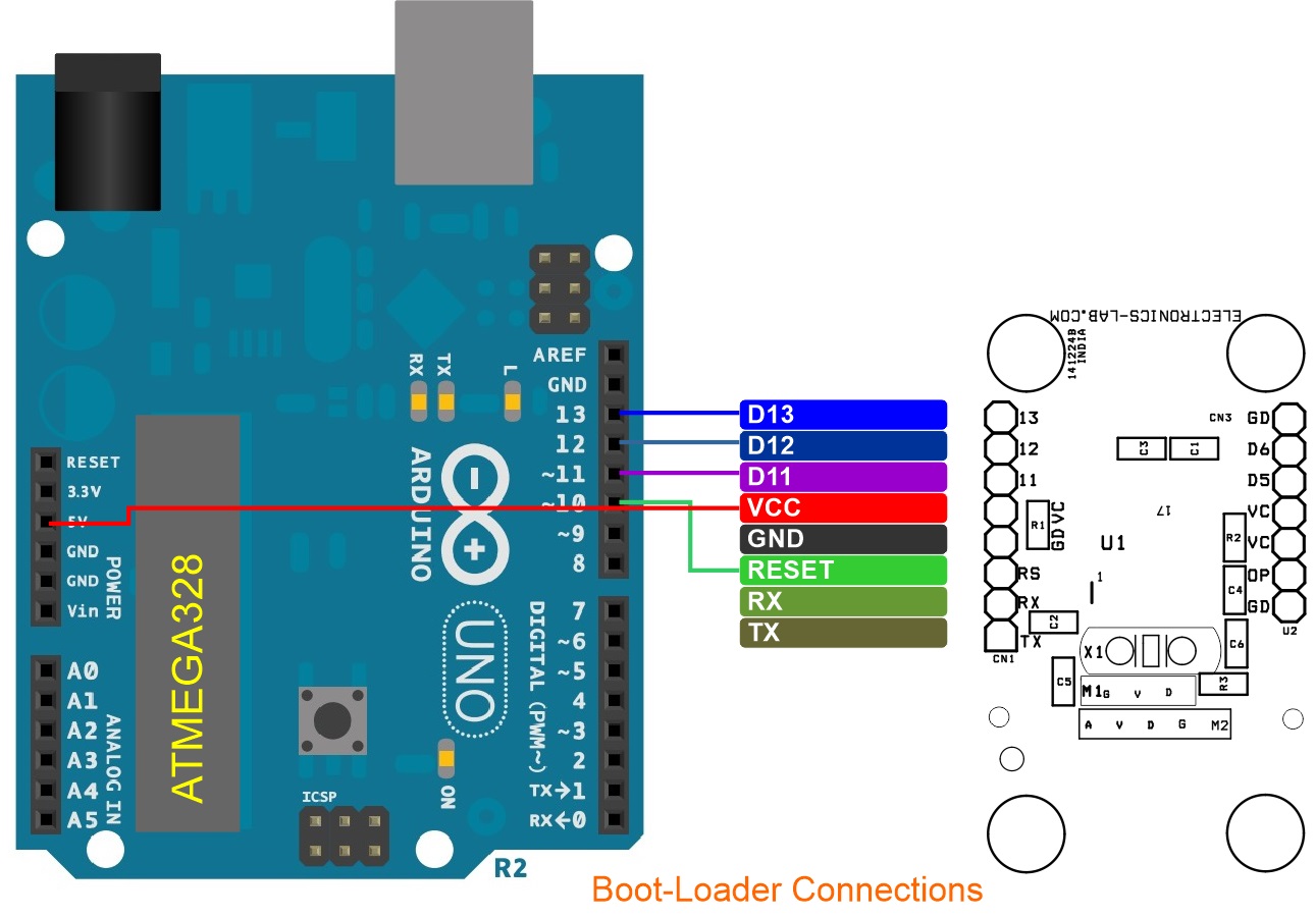
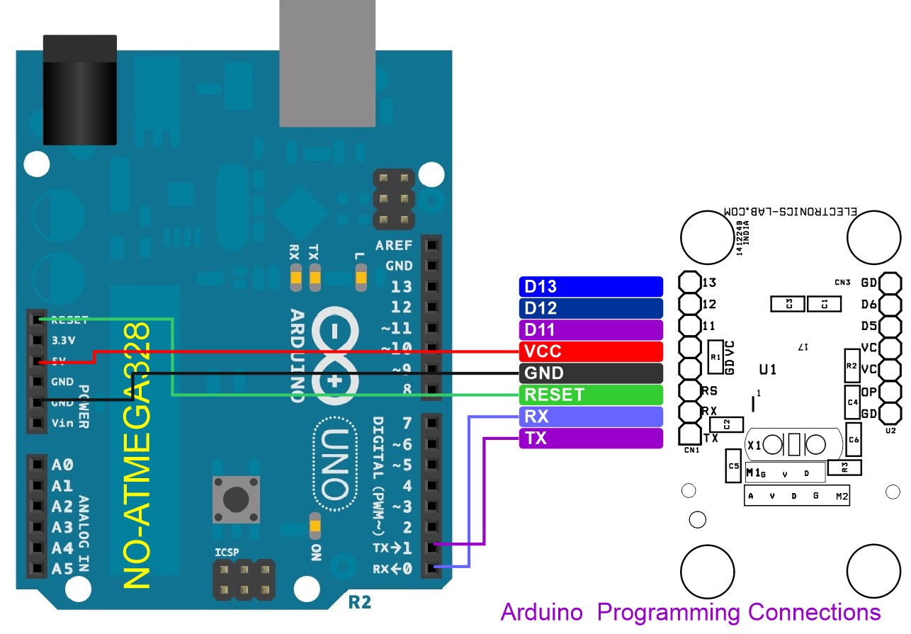
The Arduino code for this project is available for download. Before uploading the code to the ATMEGA328 microcontroller, users must first burn the bootloader. Please refer to the connection diagram for instructions on how to connect the bootloader and program the Arduino.
In the provided Arduino code, the sensor values are mapped to a range of 0-100%. Specifically, approximate sensor values of 3 to 864 are mapped to 0-100%. Users can modify these mapping values as needed to suit their specific requirements.
The code is designed to display the light level as a percentage, with 100% indicating a full light. 50% indicating 50% light. For example, when the transmitter exposes to full sun light, the display will show 100%, and when light level is 50%, the display will show 50%. This allows for a clear and intuitive representation of the light level.
Light Source Positioning and Uniformity
The OPT101 is tested with a light source that uniformly illuminates the full area of the integrated circuit, including the op amp. Although the silicon of integrated circuit (IC) amplifiers is light-sensitive to some degree, the OPT101 op amp circuitry is designed to minimize this effect. Sensitive junctions are shielded with metal, and the photodiode area is very large relative to the op amp input circuitry. If the light source is focused to a small area, be sure that it is properly aimed to fall on the photodiode. A narrowly-focused beam falling only on the photodiode provides improved settling times compared to a source that uniformly illuminates the full area of the die. If a narrowly-focused light source misses the photodiode area and falls only on the op amp circuitry, the OPT101 does not perform properly. The large 0.09-in × 0.09-in (2.29 mm × 2.29 mm) photodiode area allows easy positioning of narrowly-focused light sources. The photodiode area is easily visible because the area appears very dark compared to the surrounding active circuitry. The incident angle of the light source also effects the apparent sensitivity in uniform irradiance. For small incident angles, the loss in sensitivity is simply due to the smaller effective light gathering area of the photodiode (proportional to the cosine of the angle). At a greater incident angle, light is diffracted and scattered by the package.
Sensor Spectral Responsivity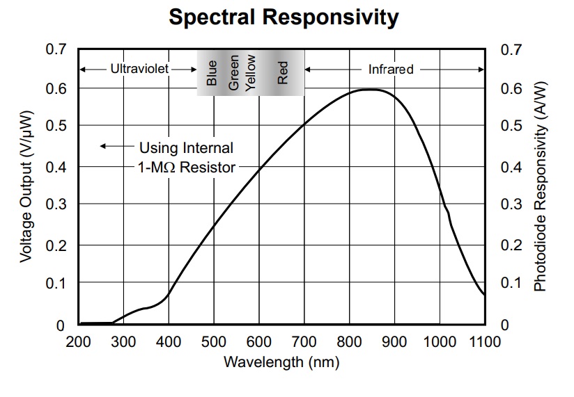
The OPT101 is a monolithic photodiode with on-chip transimpedance amplifier. The integrated combination of photodiode and transimpedance amplifier on a single chip eliminates the problems commonly encountered in discrete designs, such as leakage current errors, noise pick-up, and gain peaking as a result of stray capacitance. Output voltage increases linearly with light intensity. The amplifier is designed for single or dual power-supply operation. The 0.09 inch × 0.09-inch (2.29 mm × 2.29 mm) photodiode operates in the photoconductive mode for excellent linearity and low dark current. The OPT101 operates from 2.7 V to 36 V supplies and quiescent current is only 120 µA.
OPT101 Internal Diagram
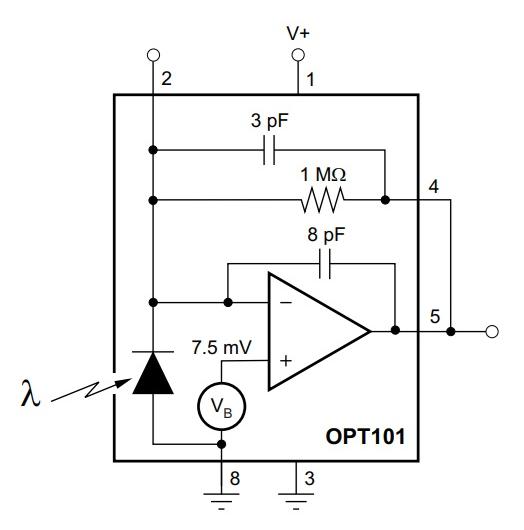
The OPT101 is a large-area photodiode integrated with an optimized operational amplifier that makes the OPT101 a small, easy-to-use, light-to-voltage device. The photodiode has a very large measurement area that collects a significant amount of light, and thus allows for high-sensitivity measurements. The photodiode has a wide spectral response with a maximum peak in the infrared spectrum, and a useable range from 300 nm to 1100 nm. The wide power-supply range of 2.7 V to 36 V makes this device useful in a variety of architectures; from all-analog circuits to data conversion base circuits. The on-chip voltage source keeps the amplifier in a good operating region, even at low light levels. The OPT101 voltage output is the product of the photodiode current times the feedback resistor, (IDRF), plus a pedestal voltage, VB, of approximately 7.5 mV introduced for single-supply operation. Output is 7.5 mV dc with no light, and increases with increasing illumination. Photodiode current, ID, is proportional to the radiant power, or flux, (in watts) falling on the photodiode. At a wavelength of 650 nm (visible red) the photodiode responsivity, RI, is approximately 0.45 A/W. Responsivity at other wavelengths is shown in Figure 1. The internal feedback resistor is laser trimmed to 1 MΩ. Using this resistor, the output voltage responsivity, RV, is approximately 0.45 V/μW at 650-nm wavelength.
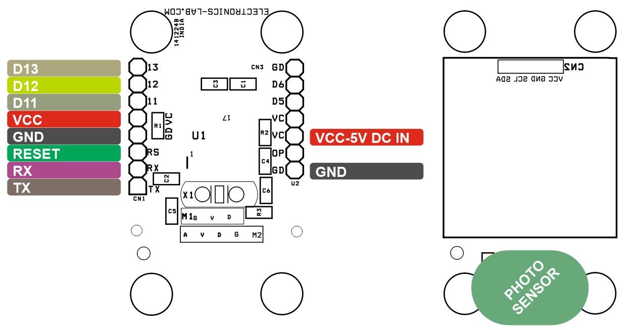
Connections
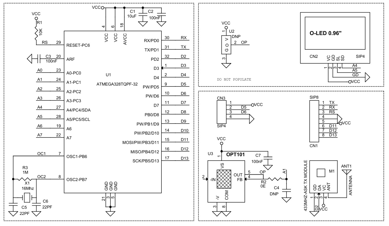
- CN1 Programmer: Pin 1 = TX, Pin 2 = RX, Pin 3 = Reset, Pin 4 = GND, Pin 5 = VCC, Pin 6 D11, Pin 7 = D12, Pin 8 = D13
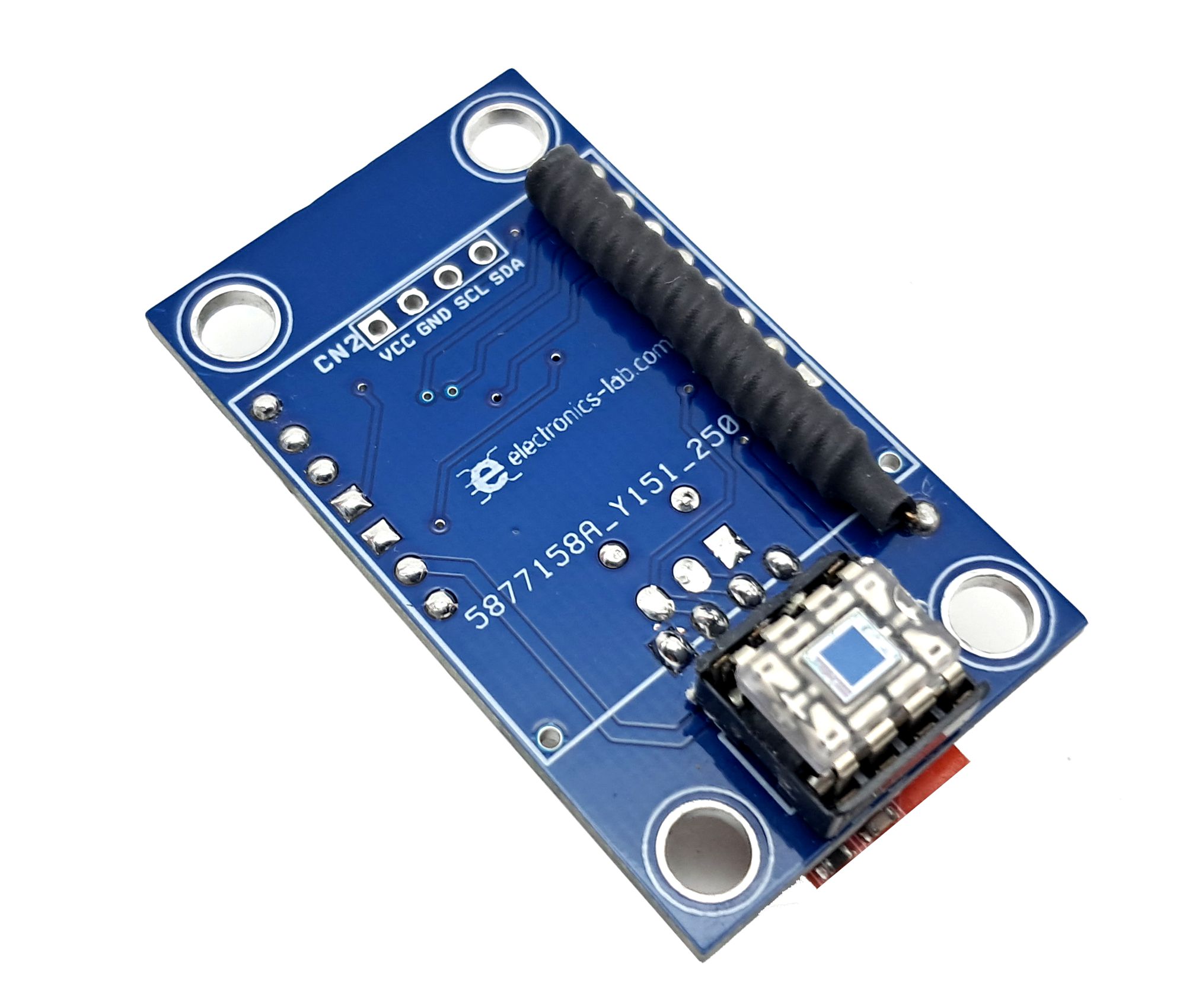
- U3: Light Sensor/Photodiode IC (OPT101)
Arduino Pins
- Photo Sensor Output = Analog Pin A1
- RF Module Data Transmitter = Digital Pin D2
Schematic
Parts List
| NO. | QNTY. | REF. | DESC. | MANUFACTURER | SUPPLIER | SUPPLIER PART NO |
|---|---|---|---|---|---|---|
| 1 | 1 | ANT1 | 15 CM HOOKUP WIRE | |||
| 2 | 1 | CN1 | 8 PIN MALE HEADER 2.54MM | WURTH | DIGIKEY | 732-5321-ND |
| 3 | 2 | CN2,CN3 | DNP | |||
| 4 | 1 | C1 | 10uF/16V CERAMIC SMD SIZE 0805 | YAGEO/MURATA | DIGIKEY | |
| 5 | 3 | C2,C3,C7 | 100nF/50V CERRAMIC SMD SIZE 0805 | YAGEO/MURATA | DIGIKEY | |
| 6 | 2 | U2,C4 | DNP | |||
| 7 | 2 | C5,C6 | 22PF/50V CERAMIC SMD SIZE 0805 | YAGEO/MURATA | DIGIKEY | |
| 8 | 1 | M1 | 433MHZ-ASK TX MODULE | CHINA | EBAY | ALIEXPRESS/AMAZON |
| 9 | 1 | R1 | 10K 5% SMD SIZE 0805 | YAGEO/MURATA | DIGIKEY | |
| 10 | 1 | R2 | 0E SMD SIZE 0805 | YAGEO/MURATA | DIGIKEY | |
| 11 | 1 | R3 | 1M 5% SMD SIZE 0805 | YAGEO/MURATA | DIGIKEY | |
| 12 | 1 | U1 | ATMEGA328TQPF-32 | MICROCHIP | DIGIKEY | ATMEGA328-AU-ND |
| 13 | 1 | U3 | OPT101 DIP8 | TI | DIGIKEY | 296-23090-5-ND |
| 14 | 1 | X1 | 16Mhz | ECS INC | DIGIKEY | X1103-ND |
Connections
Gerber View
Photos