
Qorvo QPX0252 Targets Crowded X-Band Radar Arrays
A four-channel silicon beamformer that drives front-end modules directly, shrinking the external circuitry phased-array designers must squeeze between elements.
Anyone who has tried to wedge a radar front end behind a flat-panel antenna knows just how stingy the real estate gets. Qorvo is tackling that squeeze with the QPX0252, a four-channel beamformer IC covering 7.9 to 12 GHz, announced at European Microwave Week in London on October 2, 2026. Rather than arriving as a stand-alone part, the device was conceived as one piece of a broader X-band front-end architecture, with its transmit, receive, and control functions shaped around what a radar system actually demands.
Space Is the Scarce Resource
X-band radar is steadily shifting toward active electronically scanned array (AESA) designs, including flat-panel phased arrays. In these antennas, element spacing, known as the lattice, limits the area left for beamformers, front-end modules (FEMs), and power-control devices. Every external driver amplifier claims a slice of that area; so does every discrete circuit for power-amplifier bias control and switching, and each adds another interface for the customer to manage.
The QPX0252 tackles both costs at once. Its transmit output is strong enough to drive compatible Qorvo FEMs, including the QPF5012, directly, removing the external driver stage from the signal chain. That module covers 8.5 to 10.5 GHz and folds a transmit/receive switch, limiter, low-noise amplifier, and power amplifier into a 7 x 5 mm package, delivering 10 W of saturated transmit power. Companion Qorvo devices handle GaN power amplifier bias control and RF switching, and the gate-bias, drain-bias, and switch-control parts support Tx/Rx switching in under 100 ns.
Inside the Beamformer
According to the data sheet brief, the CMOS device serves four antenna elements with a single transmit beam and dual receive beams. Phase and gain each get 6-bit control, in steps of 5.625° and 0.5 dB, respectively, while SPI selects multiple Tx/Rx operating modes. A quiet mode minimizes digital spurious content during receive, and the part also offers health monitoring, telemetry, improved-accuracy temperature sensing, and a receive crossover to ease board layout. The supply requirements are 1.8 V for the core and 3.0 V for the transmit power amplifier, all in an FC-CSP package. Calibration also gets attention: Qorvo says its patented Zero-Cal technique shortens the time needed to calibrate an array.
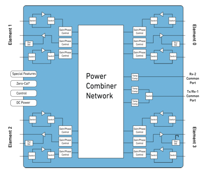
Beyond the RF paths, the block diagram shows on-chip power detectors, temperature compensation, and dedicated Zero-Cal, control, and DC power blocks. Image courtesy of Qorvo
On the receive side, Qorvo describes a division of labor. In high-power radar systems, the FEM sets a low system noise figure while the QPX0252 works in a high-linearity mode. Qorvo’s own system analysis points to up to 20 dB higher cascaded input P1dB than other offerings on the market, a figure based on the company’s analysis rather than independent testing.
Samples and Evaluation Kits
Samples and evaluation kits are available now, and the beamformer plays well with Qorvo X-band FEMs already in production across a range of power levels and configurations. The QPX0252-DL developer kit includes a test board with 18 RF connectors, a USB-to-SPI interface module, PC control software, calibration data to remove test-board losses, and Gerber files. Ordering options range from a 25-piece cut-tape sample to a 100-piece short reel and a 2,000-piece tape-and-reel. One caveat: the data sheet brief is marked preliminary and pre-production, so the listed specifications may shift.
Stepping back, the QPX0252 looks like a tidy attempt at shaving parts from the most cramped corner of a phased array: no external drivers, fewer discrete control circuits, and tighter teamwork with FEMs and bias control devices that already exist. Commercial and defense radar are the headline applications, with defense communications and weather radar also listed on the product page. Engineers fighting for every square millimeter of element lattice will probably find the developer kit a handy first stop.


