Resistors, Electromotive Force and Power Dissipation
Resistors A resistor is a passive two-terminal electrical component that implements electrical resistance as a circuit element. It is a conductor that impedes the flow of electric charge through it, creating electrical resistance.
Resistors
A resistor is a passive two-terminal electrical component that implements electrical resistance as a circuit element. It is a conductor that impedes the flow of electric charge through it, creating electrical resistance. Such resistance results from collisions between free electrons and the crystal lattice of the conductor’s atoms. This is the main property of resistors.
In electronic circuits, resistors are usually used to reduce current flow, adjust signal levels, divide voltages, bias active elements, and terminate transmission lines.
Figure 1 shows a simple circuit consisting of a battery connected to a resistor by two wires. We assume the connecting wires have no resistance. In practice, we can safely assume the current ‘I’ is the same all around the circuit.
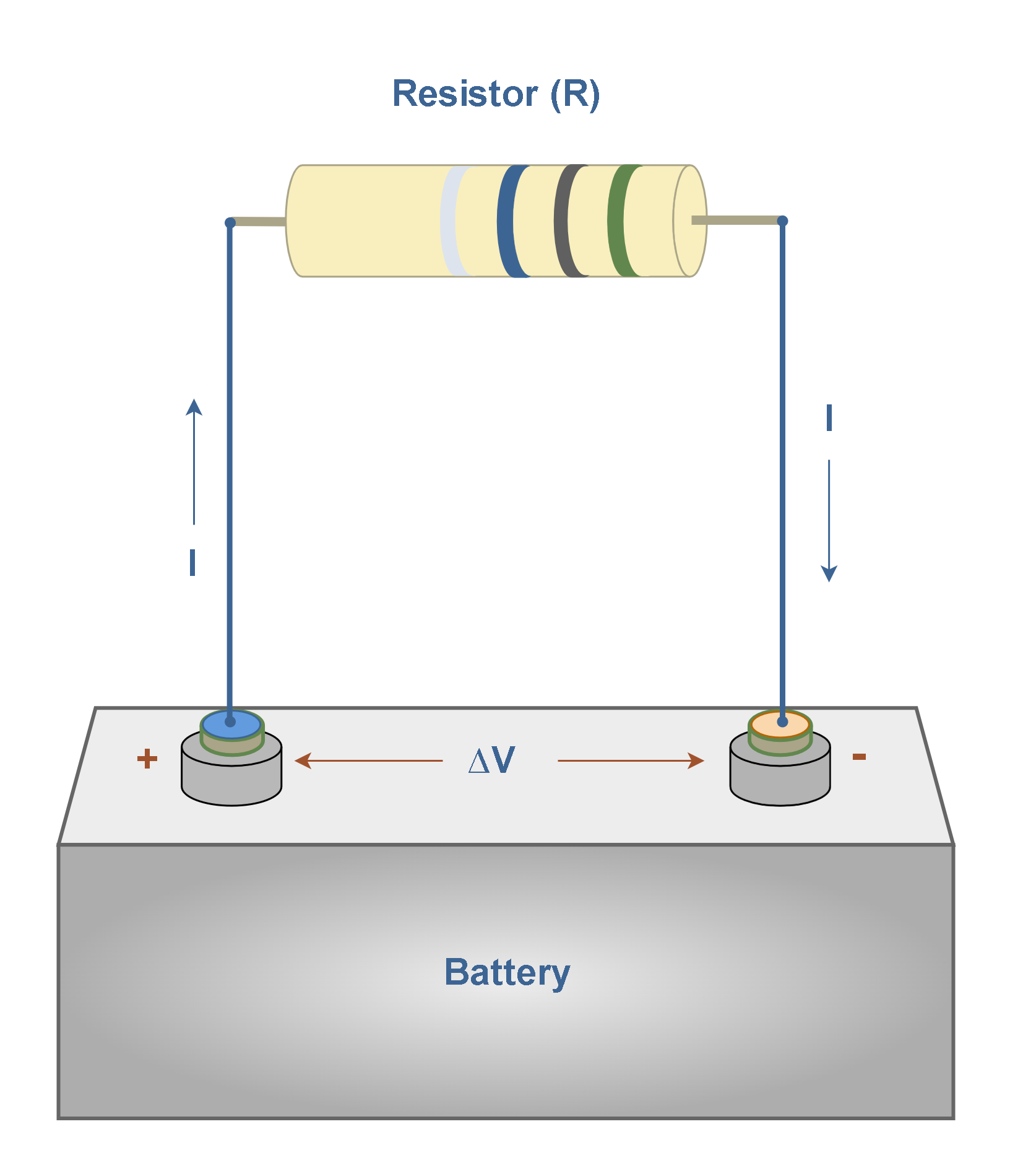
As we have already mentioned, Ohm’s Law states that the current ‘I’ through the resistor is proportional to the voltage ‘∆V’ applied across it. Equation 1 recalls this law:

where ‘R’ is called the electric resistance in units of ohms (Ω). ‘I’ is also measured in amperes and ‘∆V’ in volts.
There are many different types of resistors in the industry and they are used for many purposes. Also, in electronic circuits, resistors are often connected in series or parallel. A circuit designer might, for example, combine several resistors with standard values to reach a specific resistance value.
The most common material used to make a resistor is carbon. Figure 2 shows a typical structure of a carbon resistor.
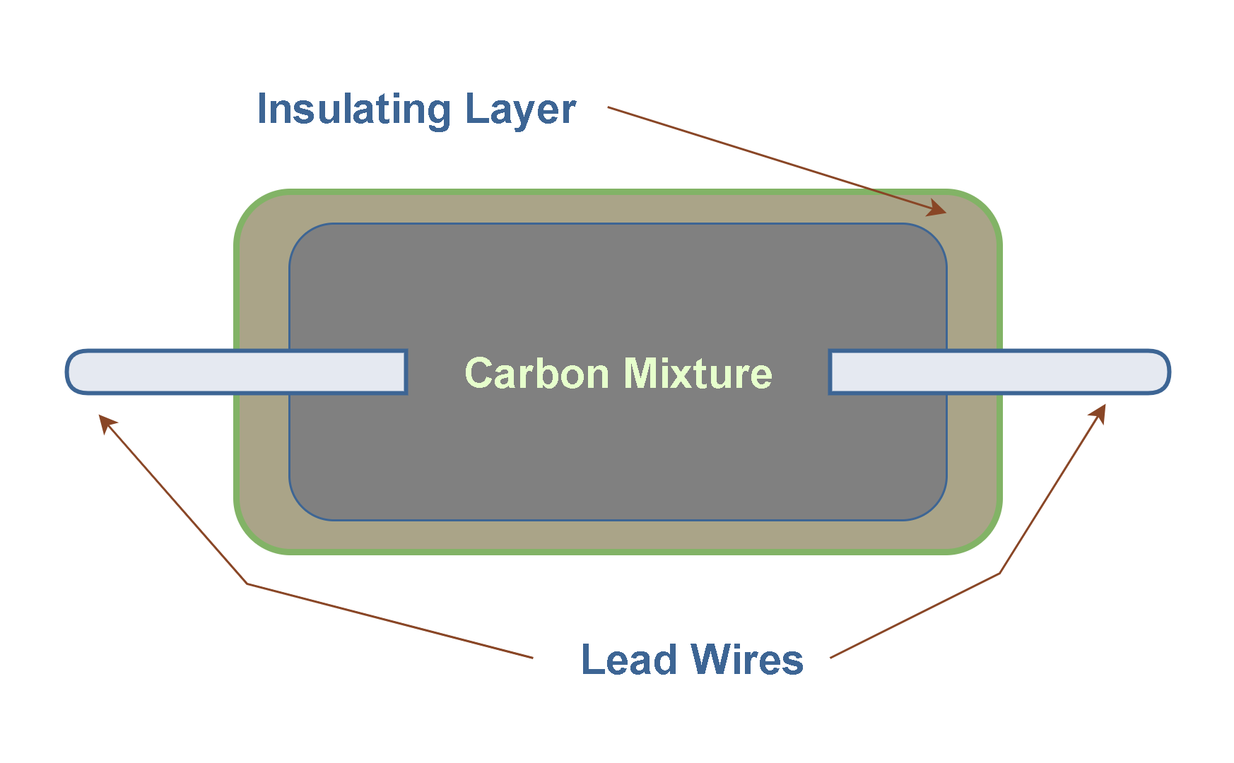
In this diagram, the carbon composition core is the actual resistive element. This main part is surrounded by an insulating layer which is typically made of ceramic material. Finally, two lead wires are used to connect the resistor to the circuit.
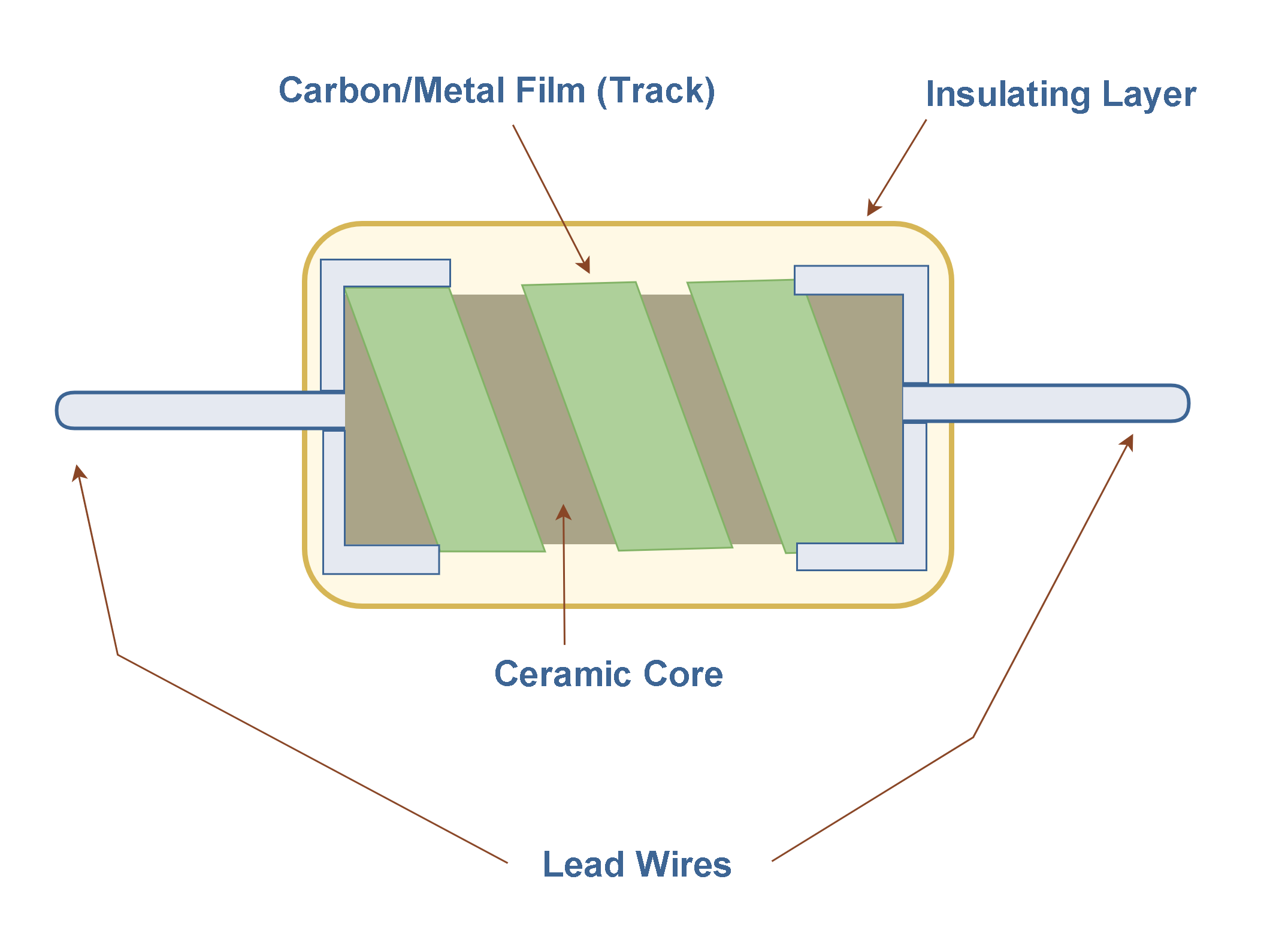
Two important categories of resistors are metal and carbon film resistors, which also have a ceramic core. In these techniques, normally a carbon/metal coating track is wrapped around a ceramic core, and two copper leads are attached. Also, the track can be made from a metal oxide material, which has semi-conductive properties similar to carbon. The spiral cuts in both types can increase the effective length of the resistive path and allow for precise resistance value adjustment.
Figure 3 shows a typical structure of such resistors.
The resistor is then painted and marked for identification. The resistance value and tolerance are normally indicated with several colored bands around the component body. This marking technique of electronic components was already developed in the 1920s.
A discrete resistor has normally four colored bands to indicate its resistance in units of ohms (Ω), as shown in Figure 4.
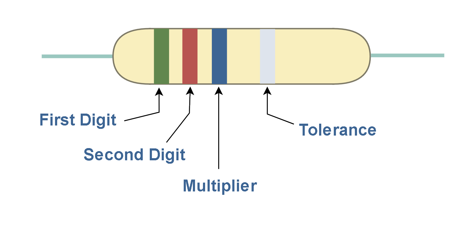
The first two colored bands represent the first two digits of the resistance of the resistor. The third color is the multiplier. The fourth color represents the tolerance of the resistor. Table 1 shows the numeric values of each color code.
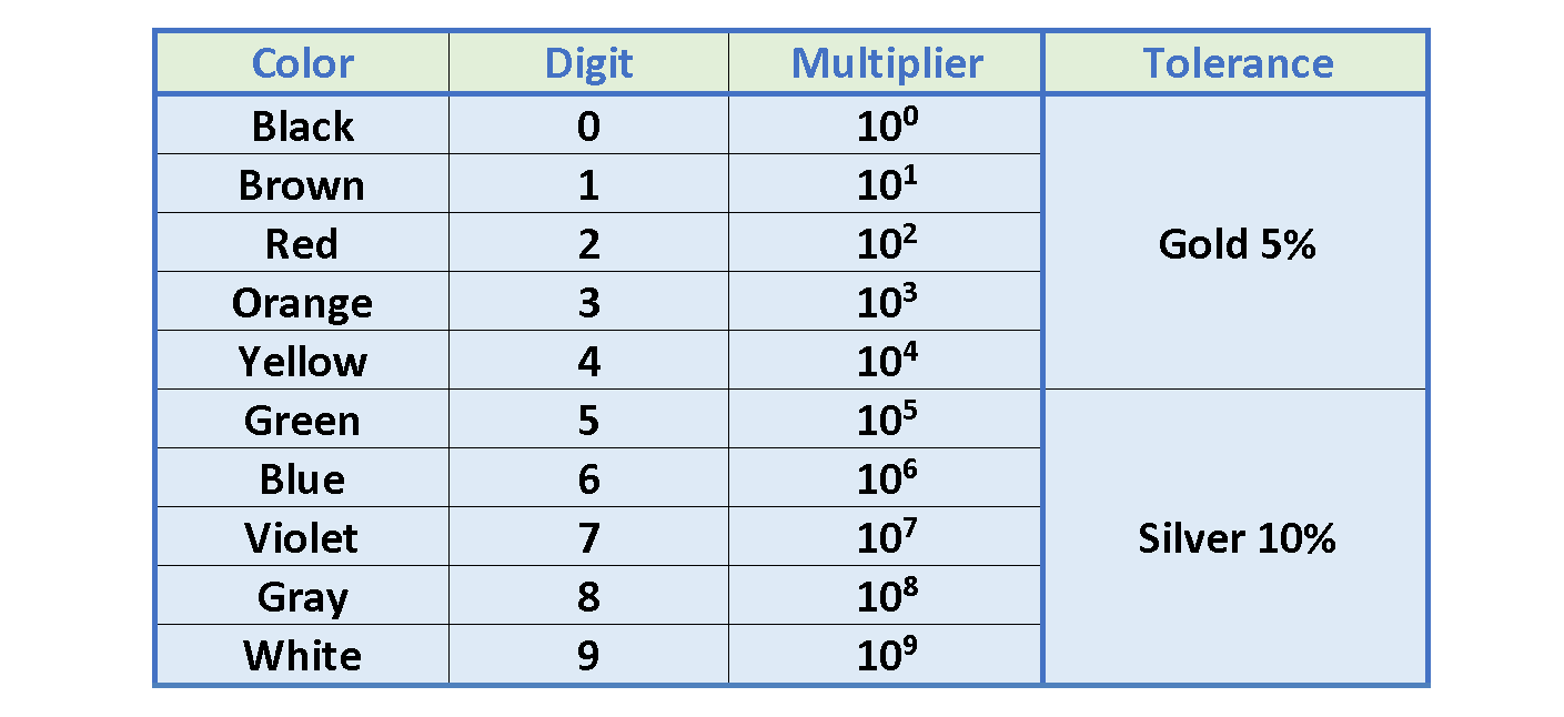
For example, the resistor shown in Figure 4, has a resistance of 52×106 Ω ± 10%.
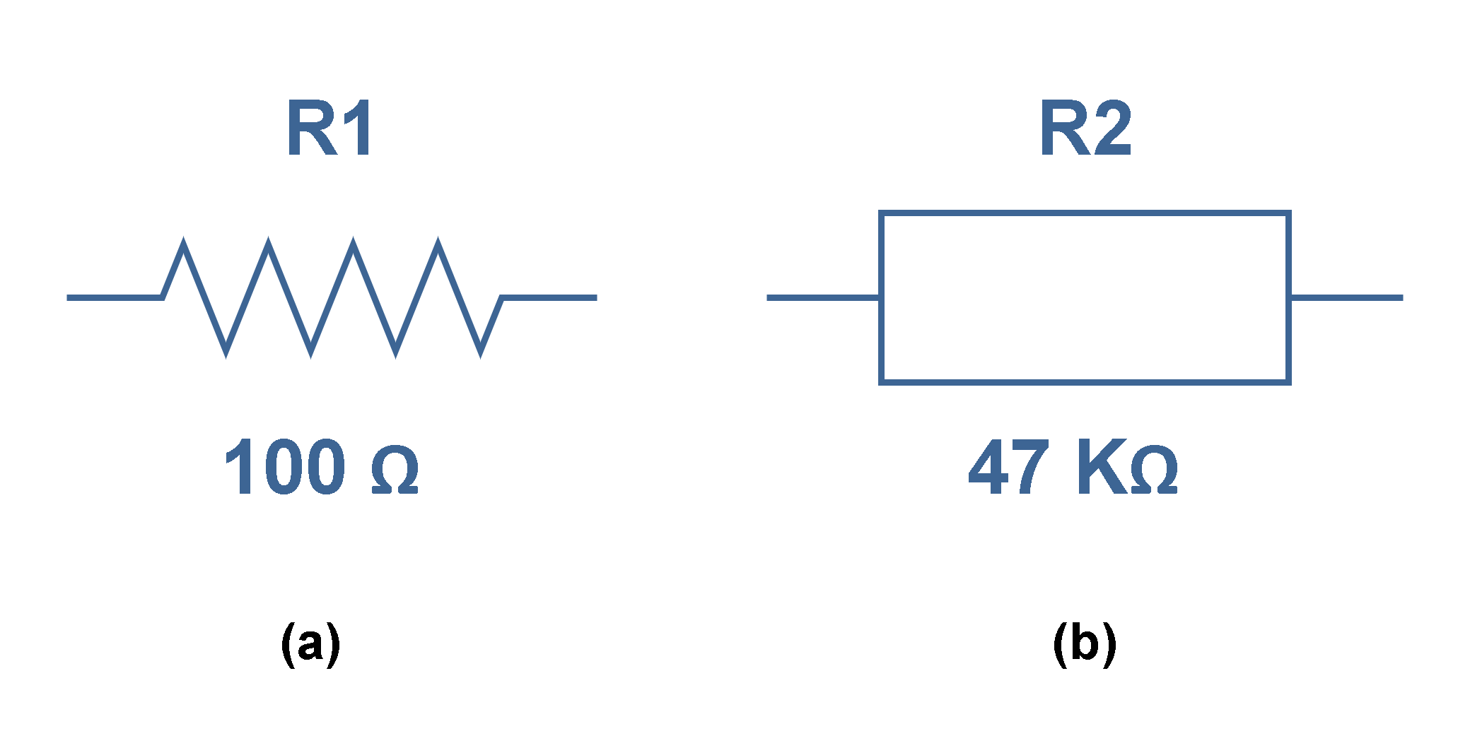
To make the symbol for a resistor in schematic circuit diagrams, there are two commonly used standards provided by the American National Standards Institute (ANSI) and the International Electrotechnical Commission (IEC). They are depicted in Figure 5:
Electromotive Force
Consider the circuit in Figure 6 consisting of a battery connected to a resistor again. We assume the connecting wires have no resistance. In practice, we can safely assume the current ‘I’ is the same all around the circuit.
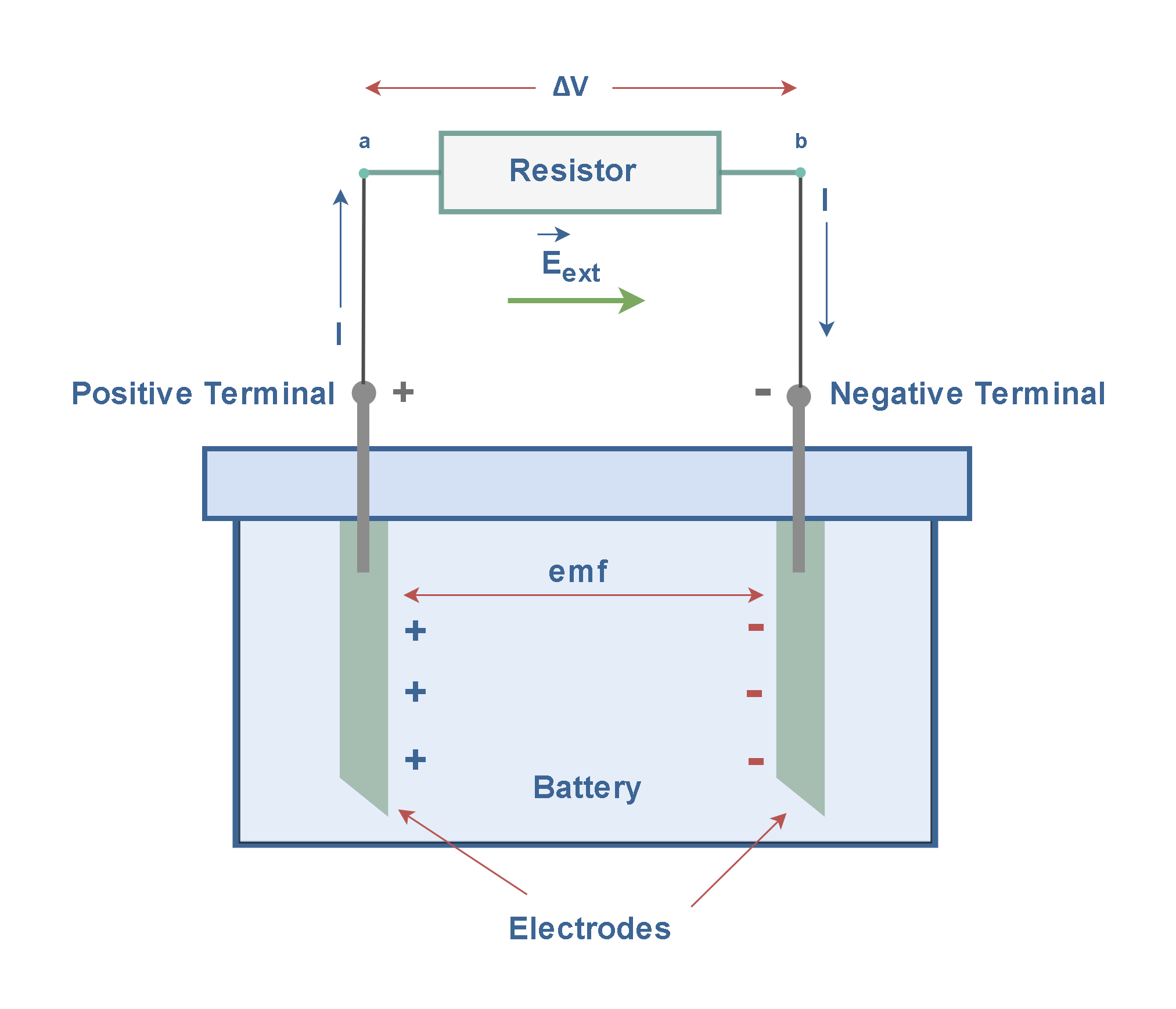
Essentially, the main force driving current around a circuit comes from the source, Fs, typically provided by a battery. The battery creates an electromotive force and drives current through the external circuit.
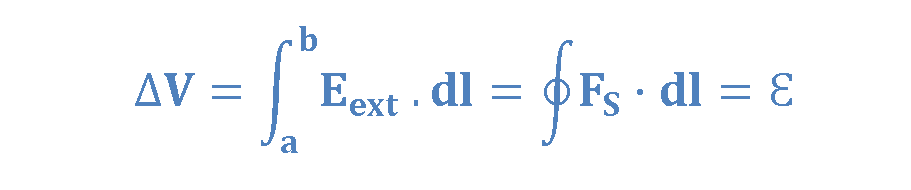
The physical activity responsible for Fs can be many different things: in a battery, it’s a chemical force. Whatever the mechanism, its net effect is defined by the line integral of Fs around the circuit, as explained by Equation 2:

where Fs is in units of Newtons (N) and dl is measured in meters (m). Then, Ԑ is called the electromotive force, or EMF, of the circuit. This term can be misleading, as it represents energy rather than force. The emf of a source is the work done per unit charge; hence the SI unit of emf is the volt.
Essentially, a source of EMF converts non-electrical energy to electrical energy; for example, batteries and electrical generators. A source of EMF can be thought of as a charge pump that forces electrons to move in a direction opposite the electrostatic field inside the source.
In Figure 6, for an ideal source of emf, the potential difference between two leads of the resistor is therefore equal to the electromotive force of the battery. Equation 3 explains this property.
Thus, a battery’s function is to maintain a voltage difference between its terminals equal to its electromotive force. The resulting electrostatic field E drives current around the rest of the circuit.THE INTERNAL RESISTANCE OF CURRENT RESOURCES
The circuit of Figure 6 can be described schematically by the diagram in Figure 7.
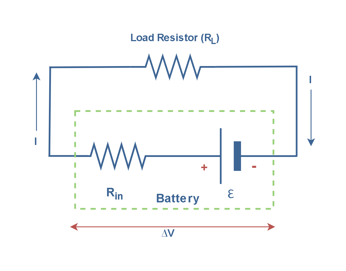
The battery, represented by the dashed rectangle, consists of a source of emf Ԑ in series with an internal resistance Rin. Now imagine a positive charge moving through the electrodes inside the battery in Figure 6. As the charge passes from the negative to the positive terminal of the battery, the potential of the charge increases by Ԑ. As the charge moves through the resistance Rin, however, its potential decreases by the amount (I. Rin), where I is the current in the circuit. The terminal voltage of the battery, ∆V, is therefore given by Equation 4:

By inspecting Figure 6, we find that the terminal voltage ∆V must also equal the potential difference across the external resistance RL, often called the load resistance; that is, ∆V = I.RL. Combining this relationship with Equation 4, we arrive at Equation 5:

Equation 5 means that the algebraic sum of all voltage drops around a closed loop in any circuit must equal zero. This principle in circuit theory is known as Kirchhoff’s voltage law (KVL)—the mesh rule. This is a consequence of energy conservation.
Solving Equation 5 for the current gives Equation 6:

Equation 6 shows that the current in this simple circuit depends on both the resistance external to the battery (load) and the internal resistance of the battery. If RL is much greater than Rin, we can neglect Rin in our analysis and conclude that the current ‘I’ will only depend on the load (I = Ԑ/RL). This is an approximation that we usually use in circuit analysis.
However, because a real battery always has some finite internal resistance Rin, the terminal voltage is not completely equal to the EMF in reality.
Electrical Energy And Power Dissipation
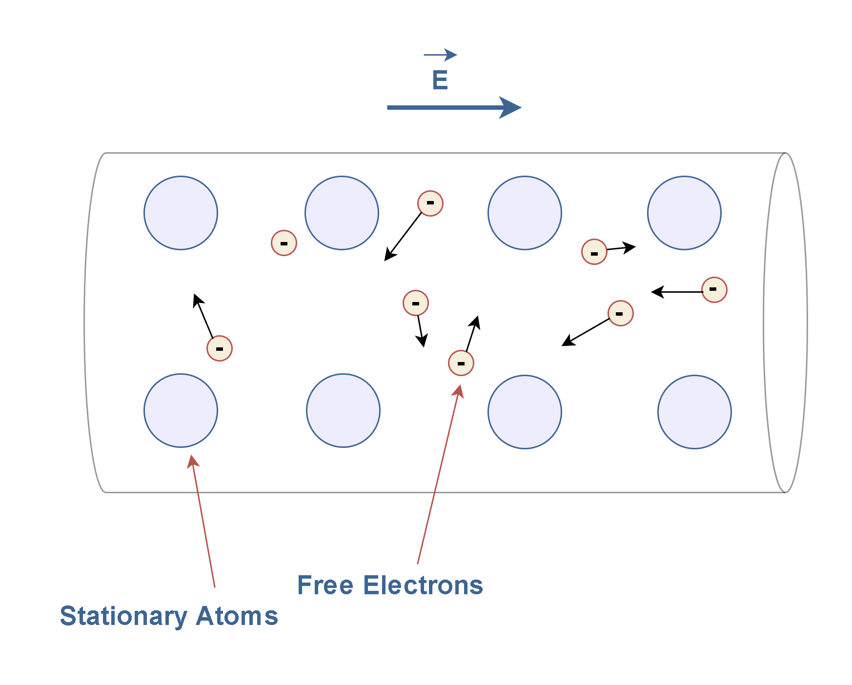
If a battery is used to establish an electric current in a conductor, the chemical energy stored in the battery is continuously transformed into kinetic energy of the charge carriers. This kinetic energy is quickly lost as a result of collisions between the charge carriers and fixed atoms in the conductor, causing an increase in the temperature of the conductor. In this way, the chemical energy stored in the battery is continuously transformed into thermal energy.
For this reason, in the circuit of Figure 6, some of the chemical energy in the battery has been delivered to the resistor and has caused its temperature to rise.
Figure 8 shows a simple model of the atomic structure of a conductor in which an applied electric field E in the conductor causes the electrons to drift in the direction opposite to the applied electric field with a drift velocity vd after some collisions with immobile atoms.
In general physics, energy is the ability to do work or make change, while power is defined as the rate of producing or consuming energy over time. The relationship between energy and power is given by Equation 7:

Energy is measured in joules (J), while power is measured in watts (W). Time is normally measured in seconds (s). The name of the energy unit refers to English physicist James Prescott Joule (1818 – 1889). The unit of power is named to honor James Watt (1736–1819), the 18th-century Scottish inventor, mechanical engineer, and inventor of the steam engine. So, one Watts of power is equal to one joule of energy transferred per second.
Essentially, the electric power is also the rate of transfer of electrical energy within a circuit of components. Similarly, the electric power is measured in units of Watts.
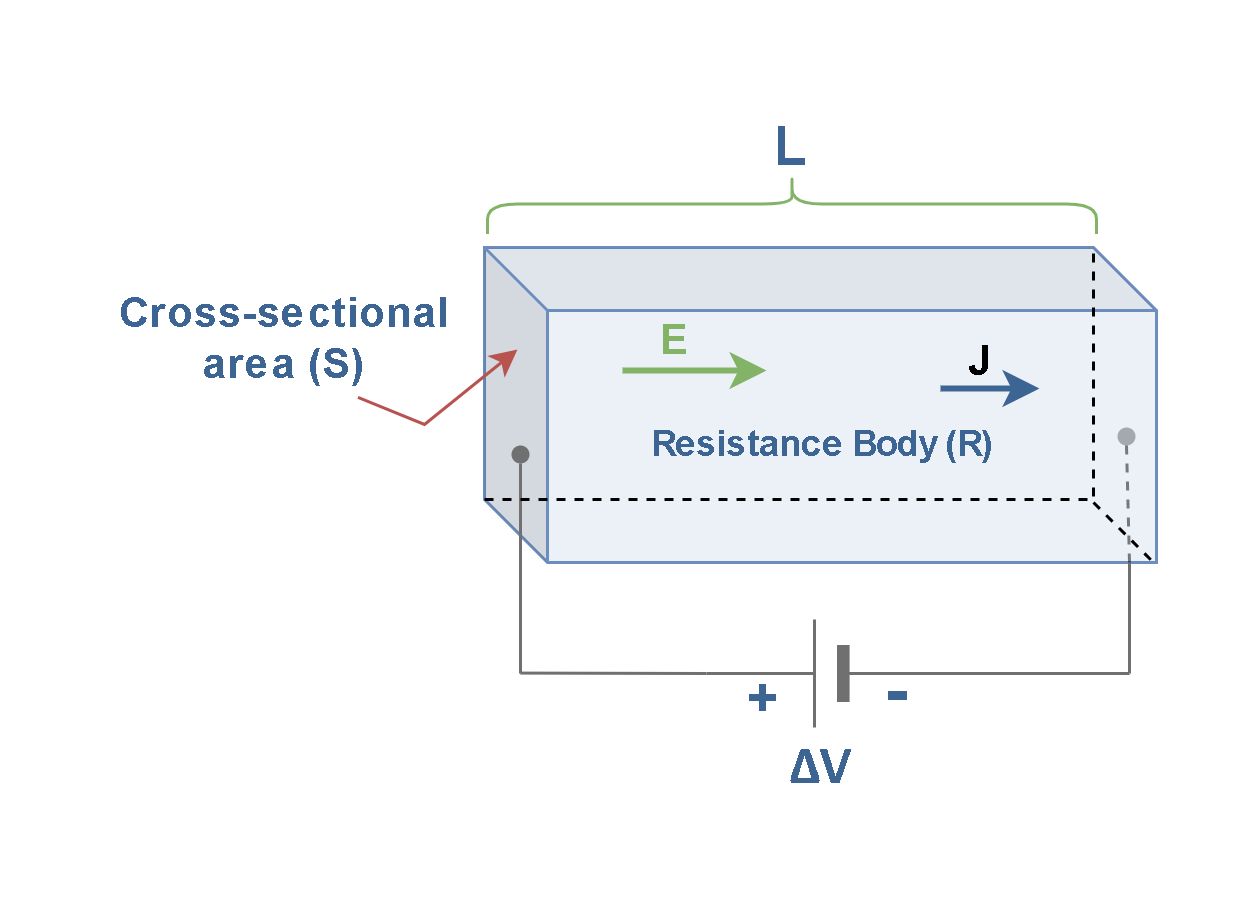
The electric power required to maintain a steady flow of current through an arbitrary conducting body of total resistance R can be found in basic principles. Figure 9 shows a resistance body by the length ‘L’ and the cross-sectional area ‘S’ which is connected to a potential difference ∆V.
The total electric power converted to heat, or dissipated power, in volume v of the conductor, can be calculated as Equation 8:

where P is the power dissipated in a continuous medium, dv is an element of volume in units of cubic meters (m3), J is the current density vector in units of amperes per square meter (A/m2) and E is the electric field vector in volts per meter (V/m). This equation is the volumetric and fundamental form of Joule’s law which quantitatively describes the rate at which heat energy (power) is produced from electric energy (power) by the resistance in a circuit.
The product of (E.J) is called the power density, under steady-current conditions, in units of Watts per cubic meter (W/m3).
In a conductor of a constant cross-section, the element of volume (dv) equals the multiplication of (S.dL), where S is the area of the cross-section and dL is the element of distance. Then the volume integral of Equation 8 can be written as a line integral in Equation 9:
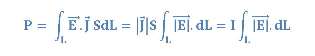
We can find out that the definition of voltage, that we mentioned in previous articles, is appeared in Equation 9. Then we can use it to find the power (P) in Equation 10 in terms of current and voltage, which represents the rate at which energy is delivered to the conductor:

where I is the steady current in units of amperes and ∆V is the potential difference across the body of the conductor/resistor in volts. This equation states that the power (in watts) equals the voltage across a component times the current passing through that component. Thus, one watt equals one volt-ampere in electrical terms.
Equation 10 can generally be used to determine the power transferred from a voltage source to any electronic component carrying a current I and having a potential difference ∆V between its terminals. It could be a resistor, a light bulb, a capacitor, or something else.
Finally, in the specific case of resistive loads (Ohmic, or linear), we can refer to Ohm’s law in Equation 1. Combining Equations 1 and 10, we can express the electric power delivered to the resistor dissipated in the alternate form of Equation 11:

This is Joule’s heating law in circuit theory. With I in amperes and R in ohms, P comes out in watts (joules per second). According to Joule’s law, the heat generated in an electric resistor is proportional to the current squared multiplied by the resistance. The power delivered from the source to a conductor of resistance R is often referred to as an I2R loss.
Note that Equation 11 applies only to resistors and not to nonohmic devices such as lightbulbs and diodes.
From the standpoint of electric power, components in an electric circuit can be divided into two categories:
- Active devices (power sources), such as electric generators and batteries;
- Passive devices (loads), which ‘consume’ electric power from the circuit.
Lamps, diodes, and other electronic components also come with maximum power ratings. If we use them at power levels higher than their ratings, this excessive power causes damage and failure.
When we select the part, we should consider the maximum possible power the part will need to handle in the circuit. We can do this by determining the maximum current we will pass through the part and the voltage across the part, and then multiplying those quantities together (referring to Equation 10). Then, we can choose a part with a power rating that exceeds the estimated value of maximum power to have an adequate safety factor.
Summary
- The resistor is a passive electrical device that provides resistance to the flow of electric current.
- Resistance is caused by collisions between free electrons and the crystal lattice in the conductor.
- In carbon or metal film resistors, a thin film coating is deposited on a ceramic core. Then, copper leads are inserted into the ends of the resistor.
- Helical film structure is due to increase resistance path.
- Four-band paintings are usually used to identify the resistor.
- The electromotive force (emf) is work done per unit charge provided by some voltage sources, like a battery.
- The battery creates an EMF as the main force and drives current through the external circuit.
- If we neglect the internal resistance of the battery, the terminal voltage ∆V of the battery equals its emf.
- As a result of all the electron-lattice collisions, the work done by the electrical field is converted into heat in the resistor.
- Power is the rate at which electrical energy is consumed by the component.
- The SI unit of power is the watt, defined as one joule per second.
- The electric power (in watts) generally equals the voltage (in volts) across a component, times the current (in amps) passing through that component.
- Power rating is very important in electronic components because too much power can damage or destroy components.


