555 Timer Astable Circuit Calculator
In this 555 timer Astable calculator, enter the values of timing capacitor C and timing resistors R1 & R2 to calculate the frequency, period and duty cycle. Here the time period is the total time it takes to complete one on/off cycle (T1+T2), while Duty cycle is the percentage of total time for which the output is HIGH.
When a 555 timer is operating in Astable mode we obtain a pulse on the output pin whose ON time (Time high) and OFF time (Time low) can be controlled. This controlling can be done by selecting the appropriate values for the Resistor R1,R2 and capacitor C1. The above circuit can be used to produce a square wave in which the high time (T1) and low time (T2) can be calculated. This method can be used to generate clock pulses for Microcontrollers/Digital IC’s or blink an LED or any other applications where specific time intervals are needed. The output wave obtained from pin 3 is shown with markings below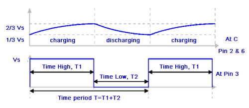 The time axis T is measured in seconds and the Voltage axis is measured in Volts. As said earlier how long the pulse stays high, how long the pulse stays low and the frequency of the pulse can be calculated using the value of components R1,R2 and C1 shown on the circuit diagram above.
The above 555 timer Astable calculator can be used to calculate these values, but to understand its working we need to know the following formulas based on which the calculator works.
The time axis T is measured in seconds and the Voltage axis is measured in Volts. As said earlier how long the pulse stays high, how long the pulse stays low and the frequency of the pulse can be calculated using the value of components R1,R2 and C1 shown on the circuit diagram above.
The above 555 timer Astable calculator can be used to calculate these values, but to understand its working we need to know the following formulas based on which the calculator works.
Note: These units are applicable only when R1 and R2 is in ohms and Capacitor is in Farads
It might be hectic to try different values of Resistor and capacitors to arrive at you desired Time interval and Frequency. So, always keep these below tips in head while selecting your values
When a 555 timer is operating in Astable mode we obtain a pulse on the output pin whose ON time (Time high) and OFF time (Time low) can be controlled. This controlling can be done by selecting the appropriate values for the Resistor R1,R2 and capacitor C1. The above circuit can be used to produce a square wave in which the high time (T1) and low time (T2) can be calculated. This method can be used to generate clock pulses for Microcontrollers/Digital IC’s or blink an LED or any other applications where specific time intervals are needed. The output wave obtained from pin 3 is shown with markings below
The time axis T is measured in seconds and the Voltage axis is measured in Volts. As said earlier how long the pulse stays high, how long the pulse stays low and the frequency of the pulse can be calculated using the value of components R1,R2 and C1 shown on the circuit diagram above.
The above 555 timer Astable calculator can be used to calculate these values, but to understand its working we need to know the following formulas based on which the calculator works.
| Parameter | Formulae | Unit |
|---|---|---|
| Time High (T1) | 0.693 × (R1+R2) × C1 | Seconds |
| Time Low (T2) | 0.693 × R2 × C1 | Seconds |
| Time Period (T) | 0.693 × (R1+2×R2) × C1 | Seconds |
| Frequency (F) | 1.44 / (R1+2×R2) × C1 | Hertz (Hz) |
| Duty Cycle | (T1/T)×100 | Percentage (%) |
TIPS:
- Period(T) and Frequency(F) are inversely proportional
- Increase in C1 will decrease Frequency (F)
- Increase in R1 will increase High Time (T1) but will not alter low Time (T2)
- Increase in R2 will increase High Time (T1) and also increase low Time (T2)
- So, always set T2 first and then T1
- Increase in R2 will decrease duty cycle