LC Tank Circuit Resonance Calculator
This calculator is made to calculate the resonance frequency of a parallel LC tank circuit, where the value of the inductor and the capacitor is known.
One of the most common examples of a tank circuit is an inductor (L) and a capacitor (C) connected in parallel. When a LC tank circuit is operating at resonance frequency, maximum power is transferred to the load or it can be said that the LC tank circuit absorbs maximum power. The above tool is designed to calculate the resonance frequency of the tank circuit when the capacitance and inductance value is known.
The resonance circuit can be used in many applications and a radio without a tank circuit is pretty much impossible even in this day and age. A typical transmitter and receiver involves a class C amplifier with a tank circuit as load. When powered the tank circuit states to resonate thus the signal propagates to space.
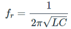 Where,
Fr = Resonance Frequency in (HZ)
L = Inductance in Henry (H)
C = Capacitance in Farad (F)
Where,
Fr = Resonance Frequency in (HZ)
L = Inductance in Henry (H)
C = Capacitance in Farad (F)
The Parallel LC Tank Circuit Calculation
Where,
Fr = Resonance Frequency in (HZ)
L = Inductance in Henry (H)
C = Capacitance in Farad (F)