Encoder-Controlled Potentiometer
Author: Marian Hryntsiv, Documentation Engineer, Dialog Semiconductor Introduction There is a variety of applications where a mechanical potentiometer is part of a user control interface. These mechanical potentiometers can be changed to more updated and reliable encoder-controlled elements and digital rheostats, being components that change the electrical parameters of the signal.
Author: Marian Hryntsiv, Documentation Engineer, Dialog Semiconductor
Introduction
There is a variety of applications where a mechanical potentiometer is part of a user control interface. These mechanical potentiometers can be changed to more updated and reliable encoder-controlled elements and digital rheostats, being components that change the electrical parameters of the signal.
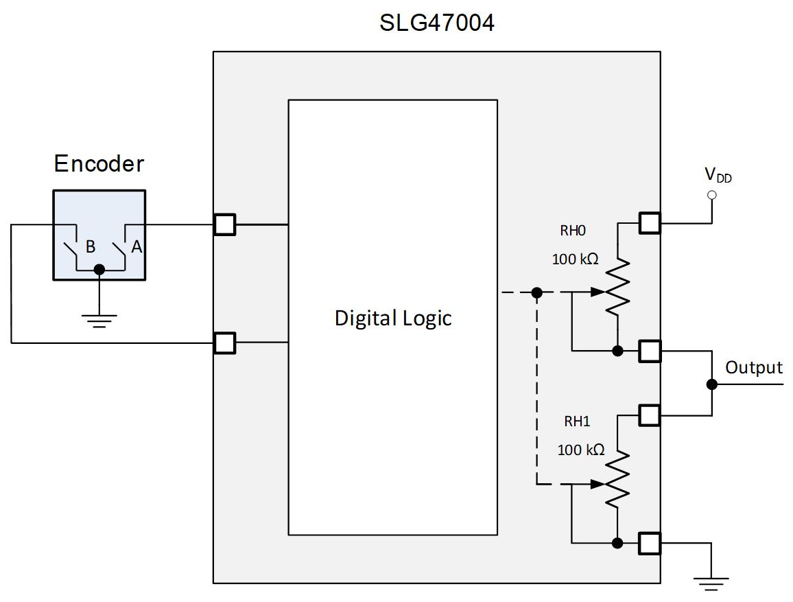
In this article, we used GreenPAK™ SLG47004. It is a great choice for this project as this circuit combines two digital rheostats and configurable logic to process the encoder information. This combination allows the implementation of many designs: a regulated power supply, an amplifier with a tunable gain, and others. In addition, the presence of digital logic allows determining the speed of rotation of the encoder. This approach is shown in Figure 1.
1. System Overview
Figure 2 shows the internal circuit design based on the SLG47004.
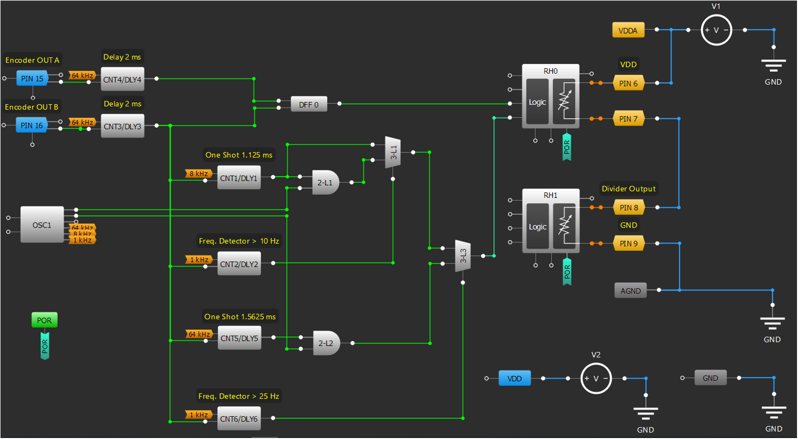
The complete design file created in free GUI-based software – GreenPAK Designer – can be found here.
An incremental encoder generates its A and B output signals which are used to change digital rheostats resistance. Rheostats form the potentiometer and allow the implementation of the adjustable voltage divider to regulate an output voltage.
At any time, the phase difference between the A and B signals will be positive or negative depending on the encoder’s direction of movement.
A speed determination function is built from Frequency Detectors, One-Shots, and Multiplexers.
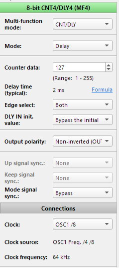
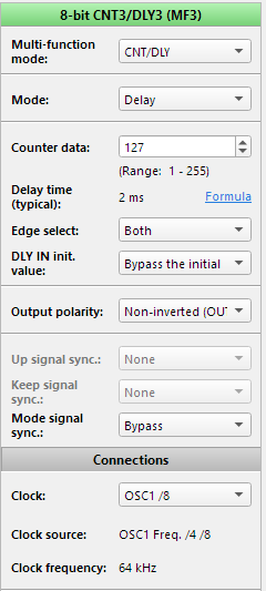
In this article, the EC11 encoder was used. The encoder produces noisy output oscillations due to a switch bounce. To eliminate that noise, 2 mS delays were used. Please note that this delay is adjusted for the EC11 encoder (according to its datasheet). For other encoders, the delay value should be assessed accordingly.
2. Functional Block Architecture
2.2. Digital Logic Description
2.1.1. Determining the Encoder Direction
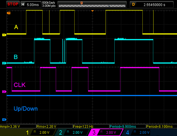
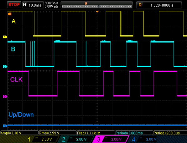
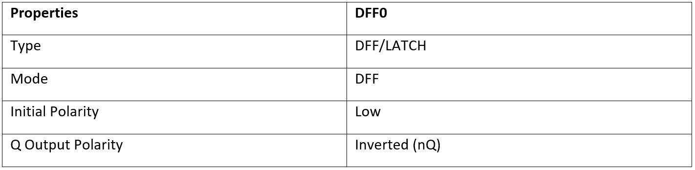
At first, Delay macrocells delay both edges of the encoder output signals for 2 mS. Delay macrocells work like a deglitch filter to eliminate switch bouncing. Delayed signal B appears on DLY inputs of One-Shots and Frequency Detectors, and CLK input of DFF. Delayed signal A appears on the D input of DFF. When the encoder disk is rotating in a clockwise direction signal A leads signal B and DFF output is High, and when the disk is rotating in a counterclockwise direction signal B leads signal A and DFF output is Low. So DFF can determine the direction of rotation. High or Low signal on Rheostat Up/Down input determines if internal counter’s value increases or decreases for each pulse at CLK input.
A timing diagram for the clockwise encoder rotation is shown in Figure 3 and for the counterclockwise encoder rotation in Figure 4.
2.1.1. Determing the Encoder Speed
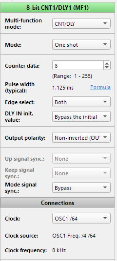
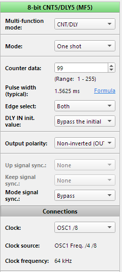
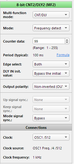
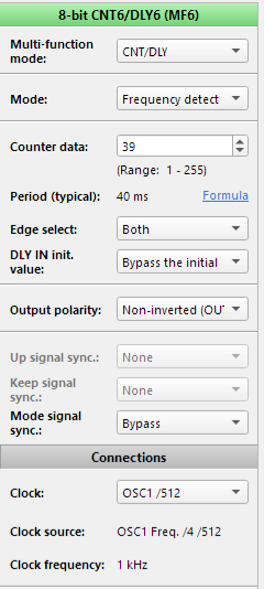
The SLG47004 has 10-bit digital rheostats, which in turn allows the implementation of 1024 regulation steps. The adjustable voltage divider has 3 regulation modes. The user can change output signal with step = 1 digital code (mode 1), step = 10 digital codes (mode 2) and step = 100 digital codes (mode 3). 2 frequency detectors were used to have 3 modes. The first mode is assigned to adjust the output signal smoothly and accurately. It activates when a user adjusts a knob with a frequency less than 10 Hz. The second mode activates when the frequency is greater than 10 Hz, but less than 25 Hz. The last one works when the frequency is greater than 25 Hz.
One-Shots set time intervals for the required number of pulses.
Digital multiplexers provide the passage of either one, or ten, or hundred pulses on CLK input of rheostat according to frequency detectors outputs.
2.1.2. Detents and Pulses per Revolution
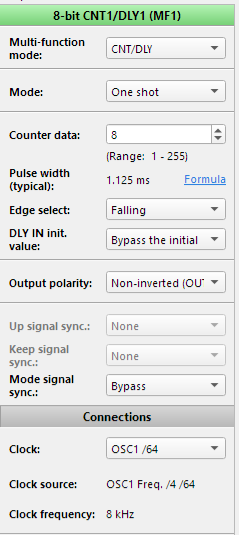
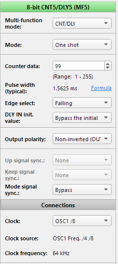
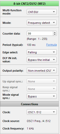
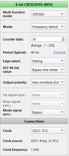
The encoder with a different number of pulses and detents (positions) was used in this project. With 15 pulses, you have two detents per full pulse. This means that for every pulse (or cycle) in the rotary encoder there are two detents: rising edge of the pulse (one change) and falling edge of the pulse (another change). If your rotary encoder has one detent per pulse, then it has two changes for every pulse. For this type of encoder, the design remains the same, except for Frequency Detectors and One-Shots settings. In their settings, Edge Select should be set “Falling” or “Rising”. In encoders where the number of pulses and detents do not match, Edge Select should be set to “Both”.
2.2. Potentiometer Mode
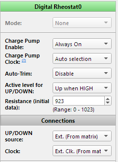
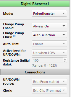
For this design, we used digital rheostats in potentiometer mode. This mode allows two 2-pin rheostats to work as one 3-pin potentiometer. When this mode is active (register [917] = 1), the user changes the value of the RH0 internal counter. In this mode, the value of the RH1 counter is the inverted value of the RH0 counter. Note that the RH0_B pin and the RH1_A pin must be connected externally.
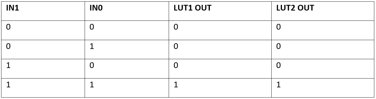
2.3. Macrocells Settings
The following tables present 3-bit LUT1 and 3-bit LUT3 settings: Standard Gate – Multiplexer.
Conclusions
The SLG47004 has two digital rheostats which allow implementing a myriad of useful applications. A case in point is using digital rheostats to replace an analog potentiometer with the help of a modern encoder. This article illustrates how to use the SLG47004 to implement the adjustable voltage divider which is a versatile solution and can be applied to an adjustable power supply, amplifier’s gain control, and others. This solution is cost-effective and has low energy consumption.


