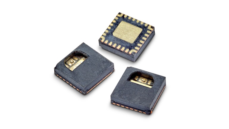
Increasing Battery Life With UB20M Voltage Detector
Engineers at the University of Bristol have developed a three terminal pico-power chip that can cut standby drain in sensor nodes – even compared with today’s low-power microcontrollers.
It does this by replacing the low duty-cycle sleep-wake-sleep pattern used on MCU-based sensor monitors, with ‘off’. A voltage detector powered by the sensor – there is no other power source – starts the processor when the sensor produces a voltage.
At 5pA (20°C 1V), power draw from the sensor through the input/supply pin is so low that the chip can directly interface with high-impedance sensors such as antennas, piezo-electric accelerometers, or photodiodes. With so little current required, the chip does not collapse the sensor voltage.
“It will work from five infra-red diodes in series, powered from a TV remote control 5m away, or an un-powered accelerometer”, Bristol engineer Bernard Stark told Electronics Weekly.
Called UB20M, the only power it draws from the system is 100pA(max) leakage through its open drain output transistor. Input threshold is set at 0.6V.

Once the sensor presents greater than 0.6V to the input, the output FET turns on (RDSon~800Ω), and its low resistance can either be used to turn on a p-FET to power up a microcontroller, or can wake a microcontroller from sleep.
In an extreme application example, said the University, an earthquake detector could be held in sleep for years, until a tremor caused the chip to wake its host.
Despite its impedance and sensitivity, the device can withstand 20V on its input/supply pin, and it has ESD protection. Maximum output pin parameters are 5.5V 7mA. Output turn-on time is 0.25μs, while turn-off depends on load resistance and capacitance – typically 8μs with a 5MΩ load and 180μs with 100MΩ.
Because patents are pending, exactly how the chip works is not being disclosed. It has around 40 transistors, and is made on a 180nm CMOS process, is all Stark could say.
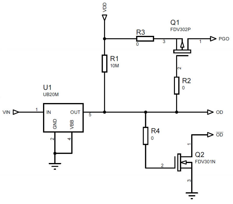
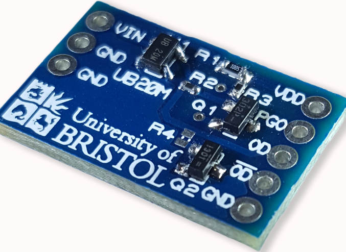
Samples are available – through a multi-project wafer deal with Europractice and IMEC, fabricated at AMS in Austria, and the University has created an evaluation board. Due to Europractice and IMEC going the extra mile, said Stark, samples are in SOT323-5 rather than clunky research packages.
The team cautions that anyone trying the chip will need to understand high-impedance circuits, as otherwise stray mains fields, for example, will trigger it continuously and the output transistor will remain on. Lengthy sensor connections should be avoided.
In general, the sensor has to be connected to the input/supply pin with enough parallel resistance to leak away stray charge and ensure the UB20M turns off.
“We are now working on ways of bringing other power drains such as data-capture, computation, and transmission, to within the nW-power budget of a sensor, completely eliminating batteries from sensor nodes,” said the University. “An example of this (right) is where power management with a few tens of nW quiescent is actively matching its input impedance to an 80MΩ energy harvester with 10 ms intermittent output pulses.”
UB20M data sheet and eval board details can be reached from this introductory web page, and there is an introductory video.
Source: Electronics Weekly


