LED Strip Effects Generator Using SLG46811V
Author: Svyatoslav Skalskyy, Product Development Engineer, Dialog Semiconductor, A Renesas Company Introduction This section introduces the subject or problem described in this document. The WS2812B is a popular intelligent RGB LED with a driver and a proprietary digital serial protocol for control.
Author: Svyatoslav Skalskyy, Product Development Engineer, Dialog Semiconductor, A Renesas Company
Introduction
This section introduces the subject or problem described in this document.
The WS2812B is a popular intelligent RGB LED with a driver and a proprietary digital serial protocol for control. It is widely used to make LED strips for visual decorative effects or even to make simple LED screens. In this article, we will introduce a basic design using the SLG46811 that will make a visual effect of running colors along the LED strip. 64 LEDs are soldered in a chain (an 8×8 matrix is used).
1. Address LED Controlling Techniques
There are several different techniques for controlling WS2812 LED strips. Different types of MCUs are used to implement these techniques. We are introducing a new way to program an LED strip using a configurable logic IC with NVM memory, the SLG46811 IC.
1.1 Hardware Protocol
The WS2812B is a 5050-component package with a control circuit, drivers, and RGB LED. It also has a signal reshaping and amplification circuit. Data is sent in a serial manner using a single pin from transmitter to receiver. Each LED is the transmitter of a signal received from the previous LED.
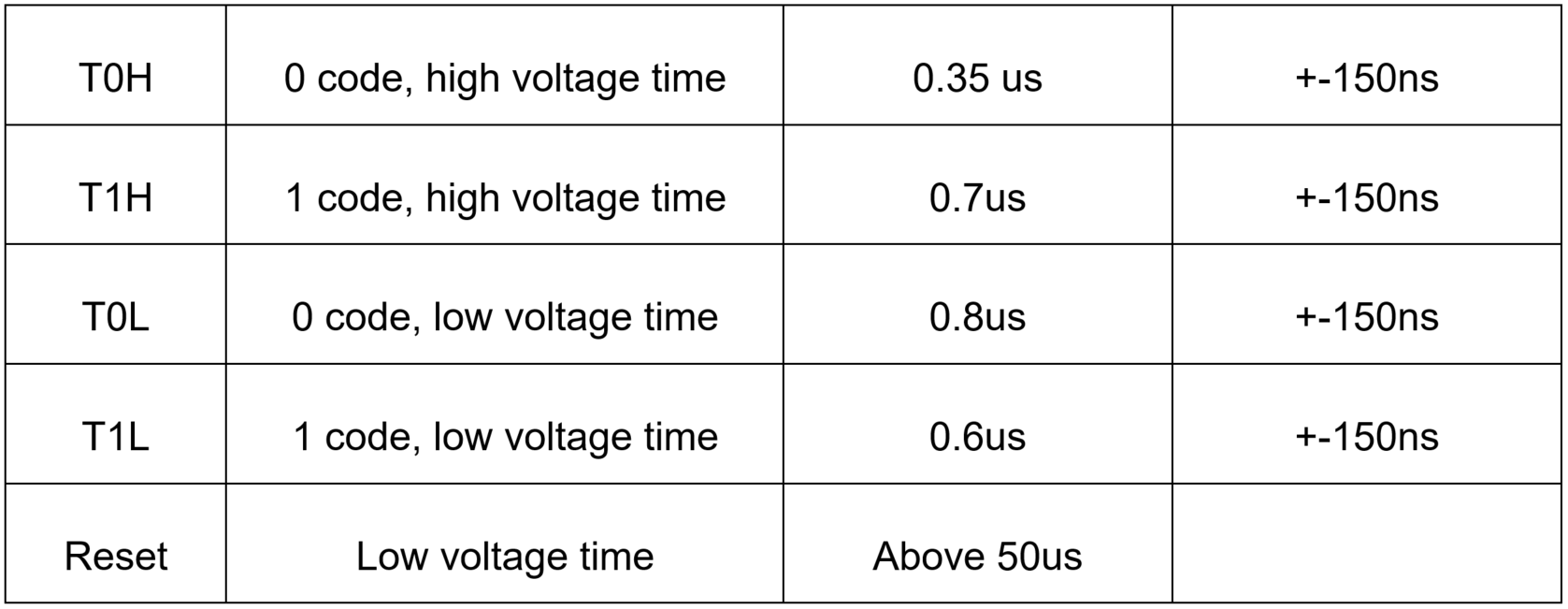
For programing LEDs, a serial bitstream of logical 0s and 1s should be transformed into pulse width modulated voltage levels (see Figure 1). The LEDs have a built-in signal form reshaping circuit, as they transmit a data sequence from the previous LED to the next one. After wave reshaping, they send all data to the next driver, ensuring waveform distortion will not accumulate. The timings are described in Figure 2.
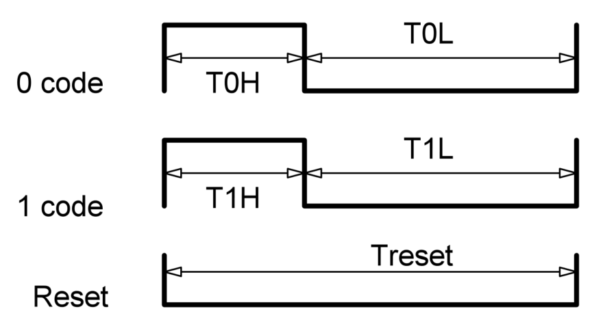
Data transfer time (TH+TL=1.25us+-600ns)
Each pixel of the three primary colors can have 256 brightness steps, completing a 16,777,216 color display with a scan frequency no less than 400 Hz.
1.2 Software Protocol
The RGB color code has 3 bytes received one after another, each byte coding 256 digits of the brightness of each LED. First, the green byte is sent, then the red, then the blue (see Figure 3).

After receiving 3 RGB bytes, the LED controller repeats all the consecutive data received from an input pin to a data output pin.
When the low-level signal is held throughout the period > 50 us, all the received data is latched and displayed by the LEDs.
1.3 Proposed Electrical Connection
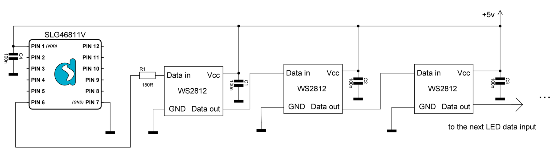
A signal pin should never have a higher voltage than Vcc. It is recommended to connect a resistor from data out pin 6 of the SLG46811 to an LED data input pin.
It is also recommended to connect all the LED Vcc pins and the SLG46811 Vcc pin in parallel to preserve this condition. A small capacitor (100 nF) is required across each LED Vcc-GND pin (see Figure 4).
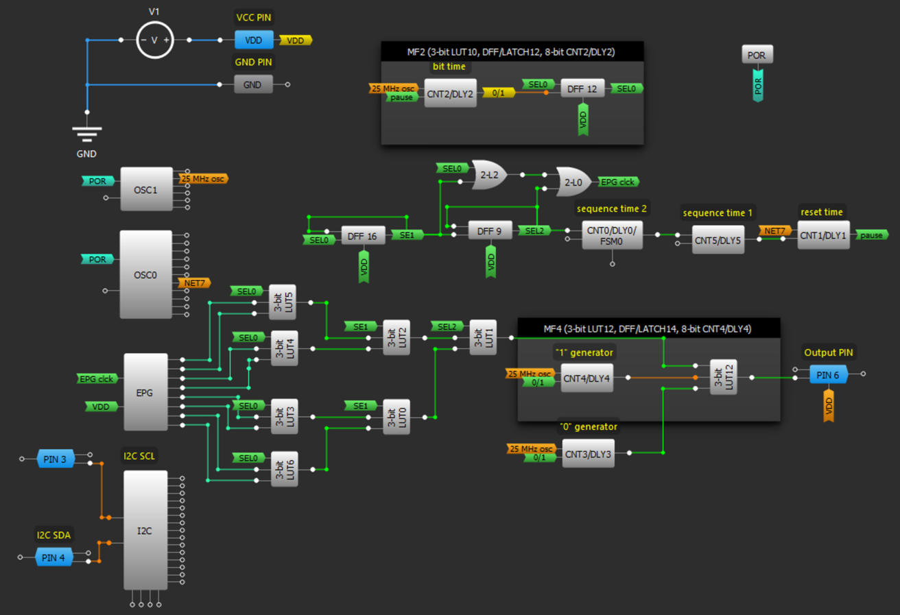
The simplified GreenPAK™ configuration scheme is shown in Figure 5.
The simplified design structure of the SLG46811 pattern generator as configured by GreenPAK Designer is shown in Figure 6.
The complete design file was developed in free GUI-based GreenPAK Designer software (the design file is available online here).
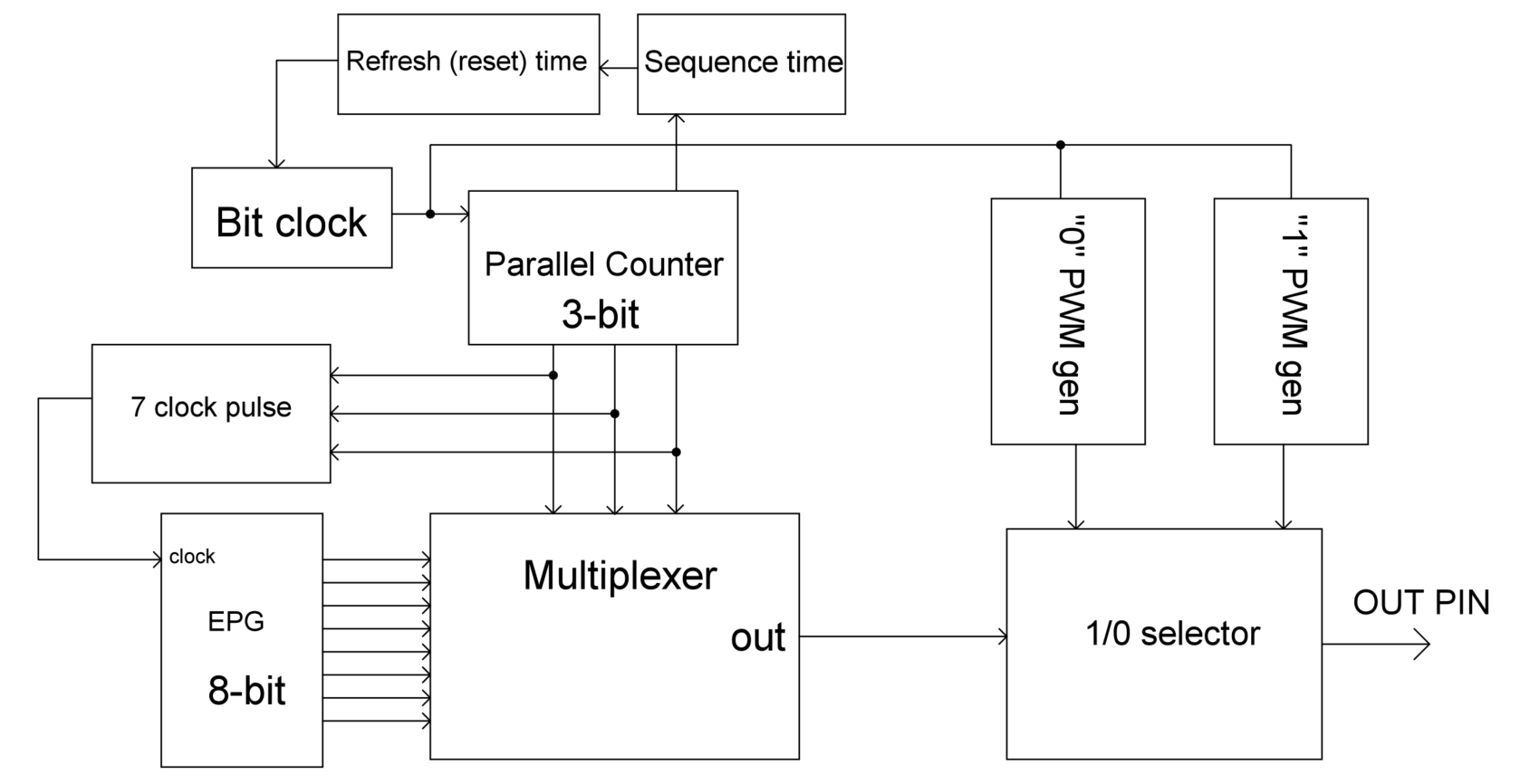
2. Internal Block Configuration
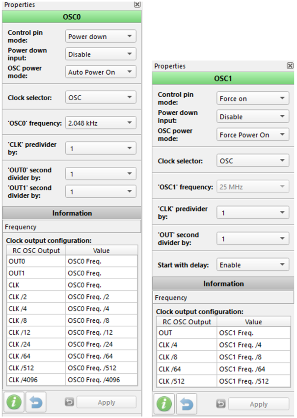
The proposed pattern generator is based on the SLG46811 IC. The internal oscillators OSC0 and OSC1 are configured to output 2.048kHz/8=256Hz and 25MHz respectively (see Figure 7).
2.1″Zero and One” Code Generator
To form a PWM with a fixed high-level time, the 8-bit CNT3 and CNT4 counter blocks are configured for 280ns and 880ns high-level period time. CNT2 is used to form a total of 1.24us one-shot time. DFF12, DFF16, and DFF9 count to 8 bits forming a byte impulse. CNT0 and CNT5 together count up to 279 bytes, which fills all the LEDs with information bits from the EPG plus an extra 3 bytes to create a shift effect. For example, 92 bytes from the EPG are sent three times in a row (92*3=279 bytes) including 3 bytes extra to make the shift effect. Each LED takes 3 bytes from a bitstream, thus 93 LEDs can be addressed. CNT1 generates a reset pause for latching all the transmitted bytes into LEDs and represents a limit of display refresh rate (which limits the visual velocity of a string movement). CNT1’s 15ms delay time will result in 66 frames per second.
2.2 Multiplexing a Bitstream
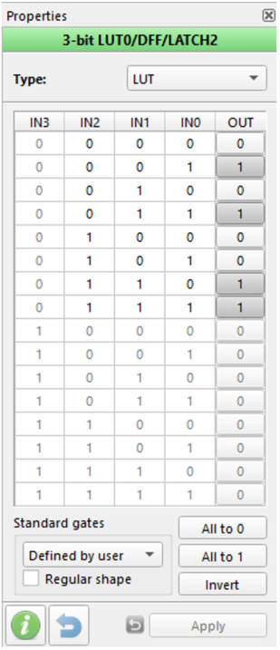
The 3-bit LUT0-LUT6 form a multiplexer, which transforms a byte from the EPG to serial bits for output.
All multiplexer LUTs have the same configuration setting shown in Figure 8.
DFF9, DFF16, and DFF12 form a 3-bit parallel counter, which addresses the multiplexer. The address is reset every byte pulse through reset inputs. The DFFs are all configured as a D flip-flop with inverted output, as shown in Figure 9.
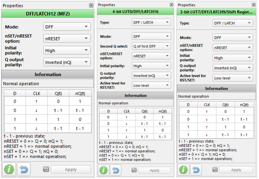
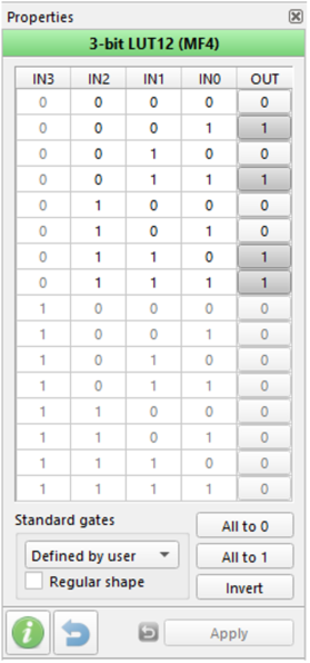
The 3-bit LUT12 selects which 0 or 1 PWM pulse to pass through to the output pin 6. The design has DFF15 configured to work as an edge detector. The configuration is shown in Figure 10.
2.2.1 EPG Configuration
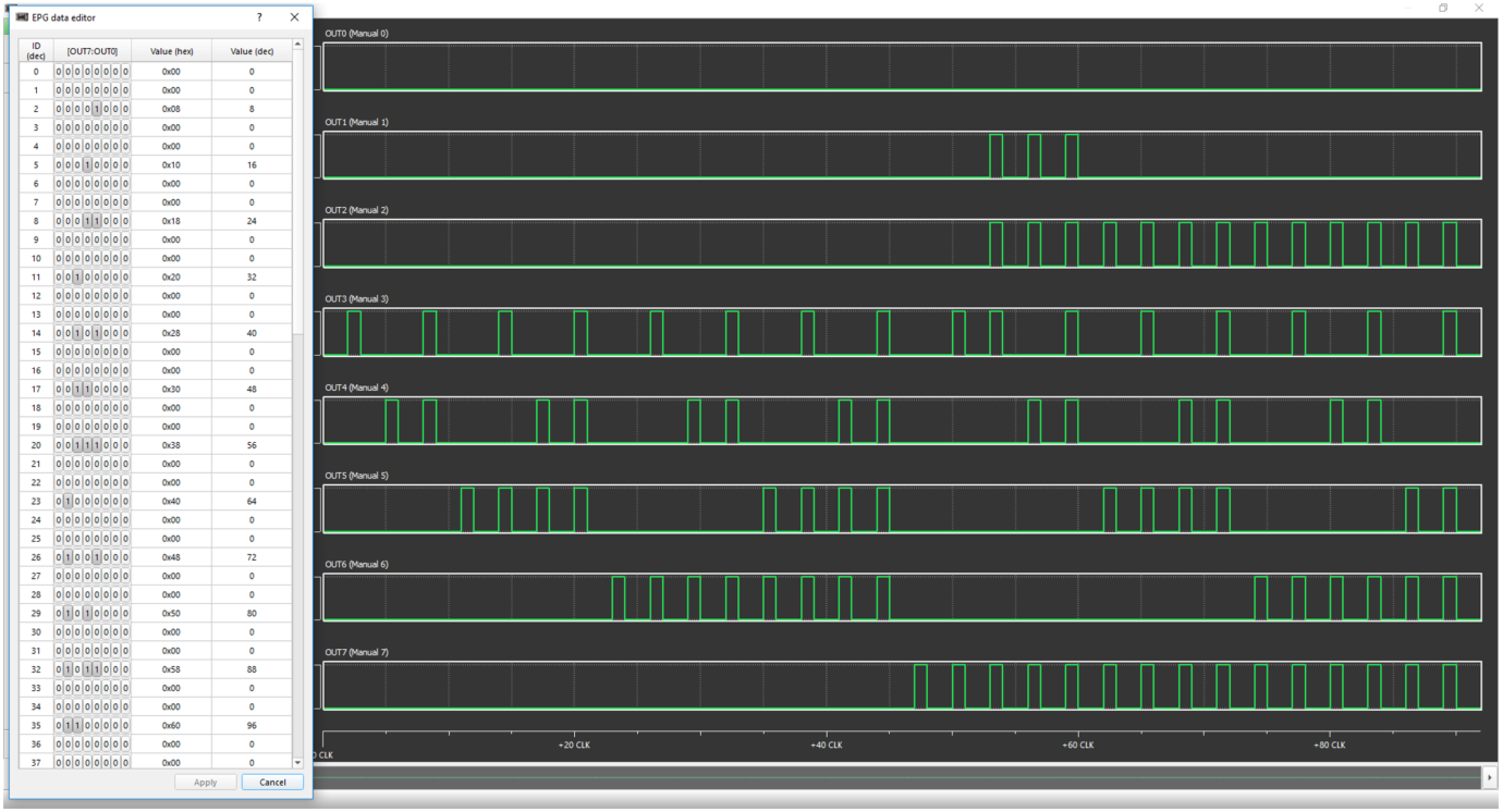
The extended pattern generator (EPG) is configured for an overflow action: after all 92 bytes are clocked out, the generator is reset to byte 0 (see Figure 11). In this design we are addressing 61 LEDs, so we are clocking the EPG two times in a row. It would be ideal to address 92 LEDs to clock the EPG 3 times. In this case, CNT0 should be configured for 276 clocks (3*92) plus 3 bytes for a shift (running string effect), thus reaching 279 in total. Entering the sequence into the EPG, users should keep in mind that 90 bytes from the generator would address 30 LEDs and the 91-92 bytes will go to the 31st LED only for green and red color bytes. The next “overflowed” first byte from the EPG will go to the blue byte of the 31st LED. So the 31st LED will have a shift of 1 byte compared to the first run of the EPG. We have to program a sequence into the EPG to make a color shift.
The programmed EPG bytes are: (0,0,8,0,0,16,0,0,24,0,0,32,0,0,40,0,0,48,0,0,56,0,0,64,0,0,72,0,0,80,0,0,88,0,0,96,0,0,104,0,0,112,0,0,128,0,0,136,0,0,142,0,0,150,0,0,158,0,0,164,0,0,172,0,0,180,0,0,188,0,0,196,0,0,204,0,0,212,0,0,220,0,0,228,0,0,236,0,0)
3. Tuning
3.1 Address LED Data Timings
There are many different modifications and manufacturers’ standards of the WS2812B LED that can differ in data timings. The best way to figure out what period of 0s and 1s you should use is to set up the SLG46811 IC in emulation mode with typical settings, connect the LED chain, and measure timings retranslated from the next LED using an oscilloscope. Use those measurements to set up the CNT3, CNT4, and CNT2 counters as zero bit width time, one-bit time, and bit period respectively.
3.2 LED Count Tuning
If you want to have a greater number of LEDs than 93, you have to add 3 to the counter value of CNT0 (2 is for 93 LEDs, 5 will give you 186 LEDs, 8 will give you 279 LEDs, and so on).
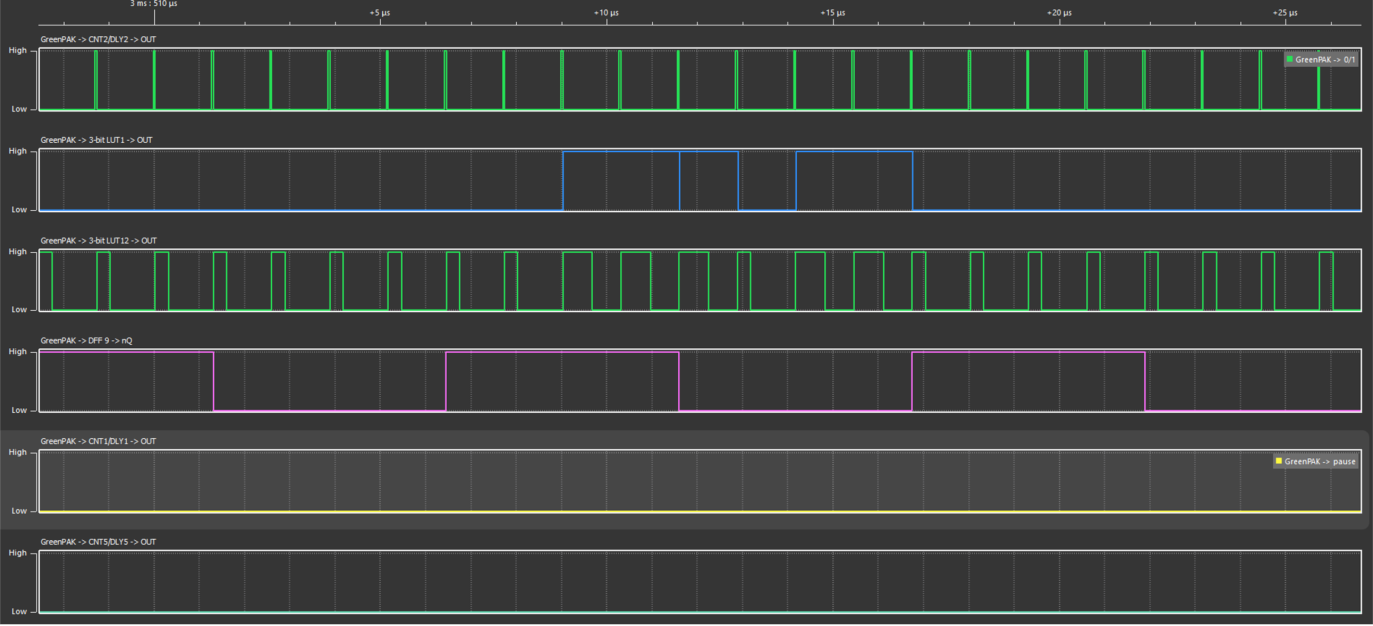
4. Normal Operation Mode
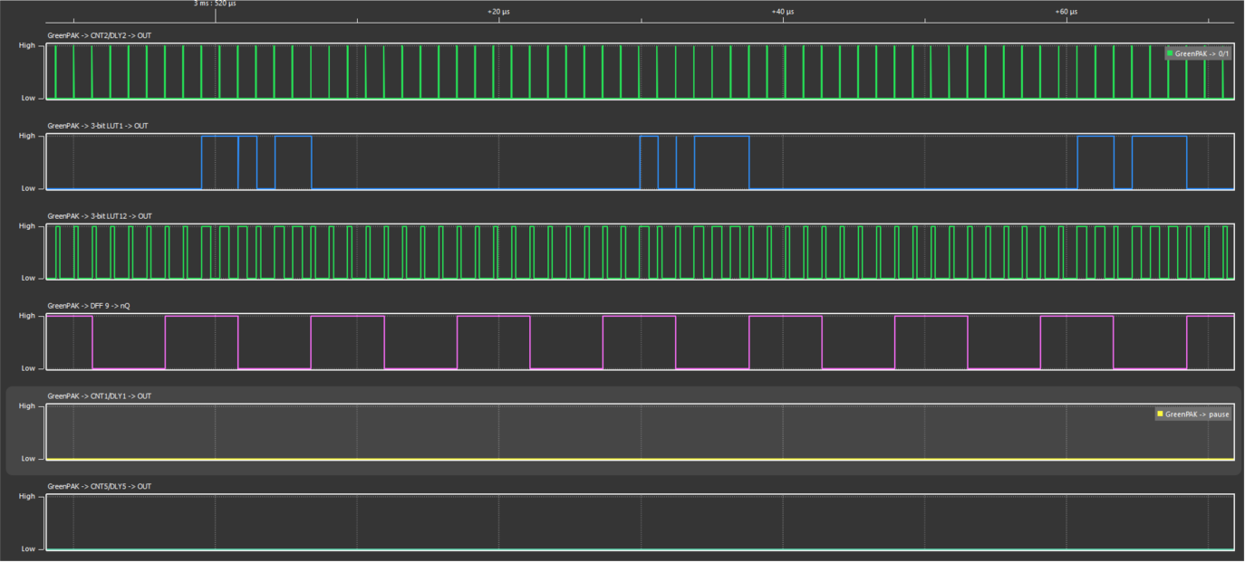
After tuning the timings and programming the EPG with the desired sequence, the SLG46811 is ready for operation. Its timing diagram is shown in Figure 13.
The oscilloscope waveform is shown in Figure 14.
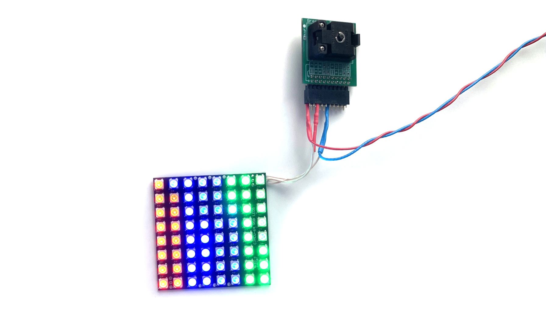
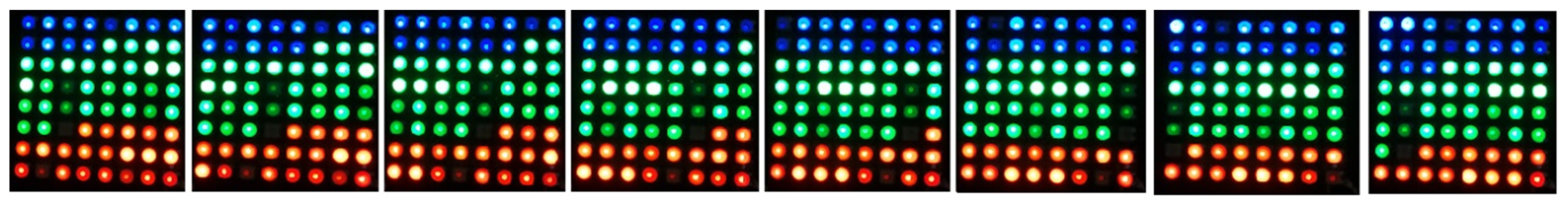
The working prototype series of photos is shown in Figure 15.

Conclusion
The proposed pattern generator using the SLG46811 in conjunction with a chain of WS2812B LEDs can deliver a “running string” of colors for a decorative visual effect.


