+/- 1.7g Dual-Axis IMEMS Accelerometer Using ADXL203
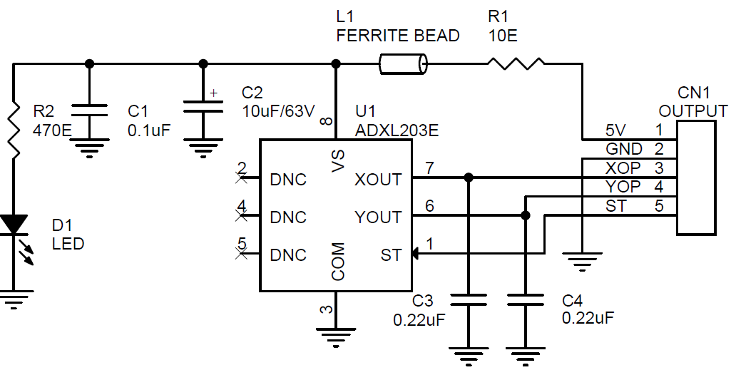
The ADXL203 Module is high precision, low power, complete dual-axis accelerometers with signal conditioned voltage outputs, all on a single, monolithic IC. The ADXL203 measure acceleration with a full-scale range of ±1.7 g, ±5 g, or ±18 g.
The ADXL203 Module is high precision, low power, complete dual-axis accelerometers with signal conditioned voltage outputs, all on a single, monolithic IC. The ADXL203 measure acceleration with a full-scale range of ±1.7 g, ±5 g, or ±18 g. The ADXL203 can measure both dynamic acceleration (for example, vibration) and static acceleration (for example, gravity).The typical noise floor is 110 μg/√Hz, allowing signals below 1 mg (0.06° of inclination) to be resolved in tilt sensing applications using narrow bandwidths (<60 Hz).The user selects the bandwidth of the accelerometer using Capacitor CX and Capacitor CY at the XOUT and YOUT pins. Bandwidths of 0.5 Hz to 2.5 kHz can be selected to suit the application.
Features
- Supply 4.75V To 5.25V
- Output 1.4V To 3V ( 2.2V Center ) Aproxx.
- High performance, dual-axis accelerometer on a single IC chip
- 5 mm × 5 mm × 2 mm LCC package
- 1 mg resolution at 60 Hz
- Low power: 700 μA at VS = 5 V (typical)
- High zero g bias stability
- High sensitivity accuracy
- −40°C to +125°C temperature range
- X and Y axes aligned to within 0.1° (typical)
- Bandwidth adjustment with a single capacitor
- Single-supply operation
- 3500 g shock survival
- Sensitivity is essentially ratiometric to VCC For VCC = 4.75 V to 5.25 V, sensitivity is 186 mV/V/g to 215 mV/V/g.
- 4 Actual frequency response controlled by user-supplied external capacitor (CX, CY).
- 5 Bandwidth = 1/(2 × π × 32 kΩ × C). For CX, CY = 0.002 μF, bandwidth = 2500 Hz. For CX, CY = 10 μF, bandwidth = 0.5 Hz. Minimum/maximum values are not tested. 6 Self-test response changes cubically with VS.
- 7 Larger values of CX, CY increase turn-on time. Turn-on time is approximately 160 × CX or CY + 4 ms, where CX, CY are in μF.
Applications
- Vehicle dynamic controls
- Electronic chassis controls
- Platform stabilization/leveling
- Navigation
- Alarms and motion detectors
- High accuracy, 2-axis tilt sensing
- Vibration monitoring and compensation
Theory of Operation
The ADXL203 are complete acceleration measurement systems on a single, monolithic IC. The is a single-axis accelerometer, and the ADXL203 is a dual-axis accelerometer. Both parts contain a polysilicon surface-micro-machined sensor and signal conditioning circuitry to implement an open-loop acceleration measurement architecture. The output signals are analog voltages that are proportional to acceleration. The ADXL203 are capable of measuring both positive and negative accelerations from ±1.7 g to at least ±18 g. The accelerometer can measure static acceleration forces, such as gravity, allowing it to be used as a tilt sensor. The sensor is a surface-micromachined polysilicon structure built on top of the silicon wafer. Polysilicon springs suspend the structure over the surface of the wafer and provide a resistance against acceleration forces. Deflection of the structure is measured using a differential capacitor that consists of independent fixed plates and plates attached to the moving mass. The fixed plates are driven by 180° out-of-phase square waves. Acceleration deflects the beam and unbalances the differential capacitor, resulting in an output square wave whose amplitude is proportional to acceleration. Phase-sensitive demodulation techniques are then used to rectify the signal and determine the direction of the acceleration.
The output of the demodulator is amplified and brought off-chip through a 32 kΩ resistor. At this point, the user can set the signal bandwidth of the device by adding a capacitor. This filtering improves measurement resolution and helps prevent aliasing. PERFORMANCE Rather than using additional temperature compensation circuitry, innovative design techniques have been used to ensure that high performance is built in. As a result, there is essentially no quantization error or nonmonotonic behavior, and temperature hysteresis is very low (typically less than 10 mg over the −40°C to +125°C temperature range). Figure 11 shows the 0 g output performance of eight parts (x and y axes) over a −40°C to +125°C temperature range. Figure 13 demonstrates the typical sensitivity shift over temperature for VS = 5 V. Sensitivity stability is optimized for VS = 5 V but is still very good over the specified range; it is typically better than ±1% over temperature at VS = 3 V.
SETTING THE BANDWIDTH USING CX AND CY
The ADXL203 has provisions for band limiting the XOUT and YOUT pins. Capacitors must be added at these pins to implement low-pass filtering for antialiasing and noise reduction. The equation for the 3 dB bandwidth is
f–3 dB = 1/(2π(32 kΩ) × C(X, Y))
or more simply,
f–3 dB = 5 μF/C(X, Y)
The tolerance of the internal resistor (RFILT) can vary typically as much as ±25% of its nominal value (32 kΩ); thus, the bandwidth varies accordingly. A minimum capacitance of 2000 pF for CX and CY is required in all cases.
Table 7. Filter Capacitor Selection, CX and CY
Bandwidth (Hz)
Capacitor (μF)
Schematic
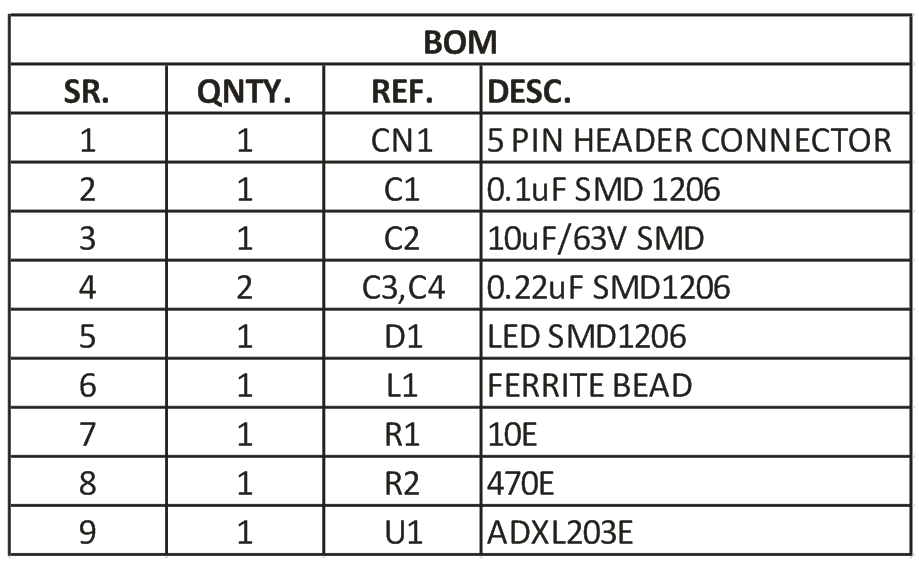
Parts List
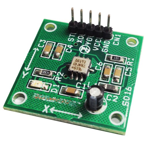
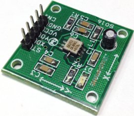
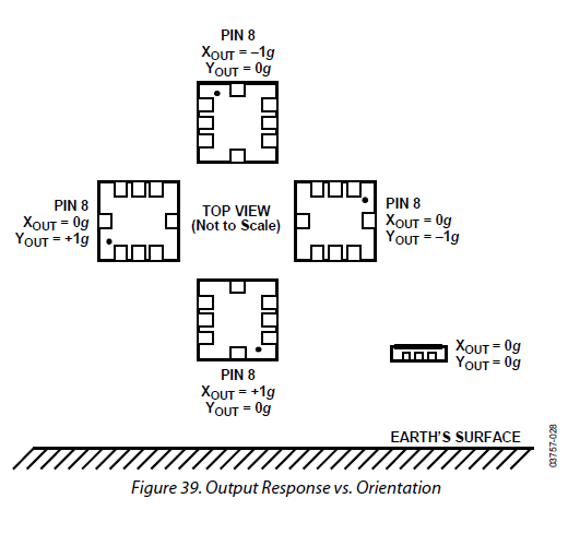
Sensor orientation
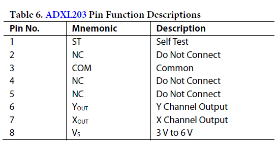
Pinout
Photos