110V – 2.5 A Floating Half-Bridge Gate Drivers with Desaturation Protection and Charge Pump
This automotive-grade board leverages the FAD3151 and FAD3171 floating gate drivers to create a robust, noise-immune half-bridge driver for high-speed MOSFET modules, offering specialized features like negative transient protection and 100% duty cycle support.

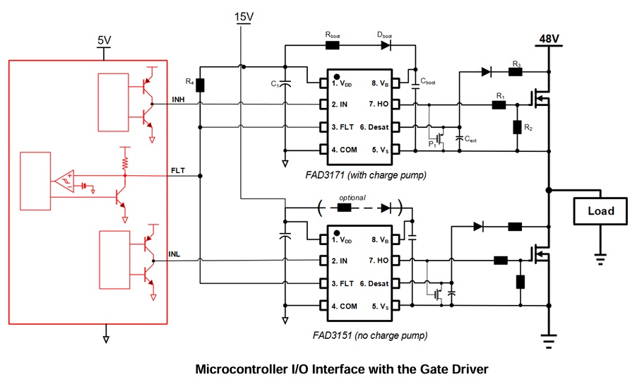
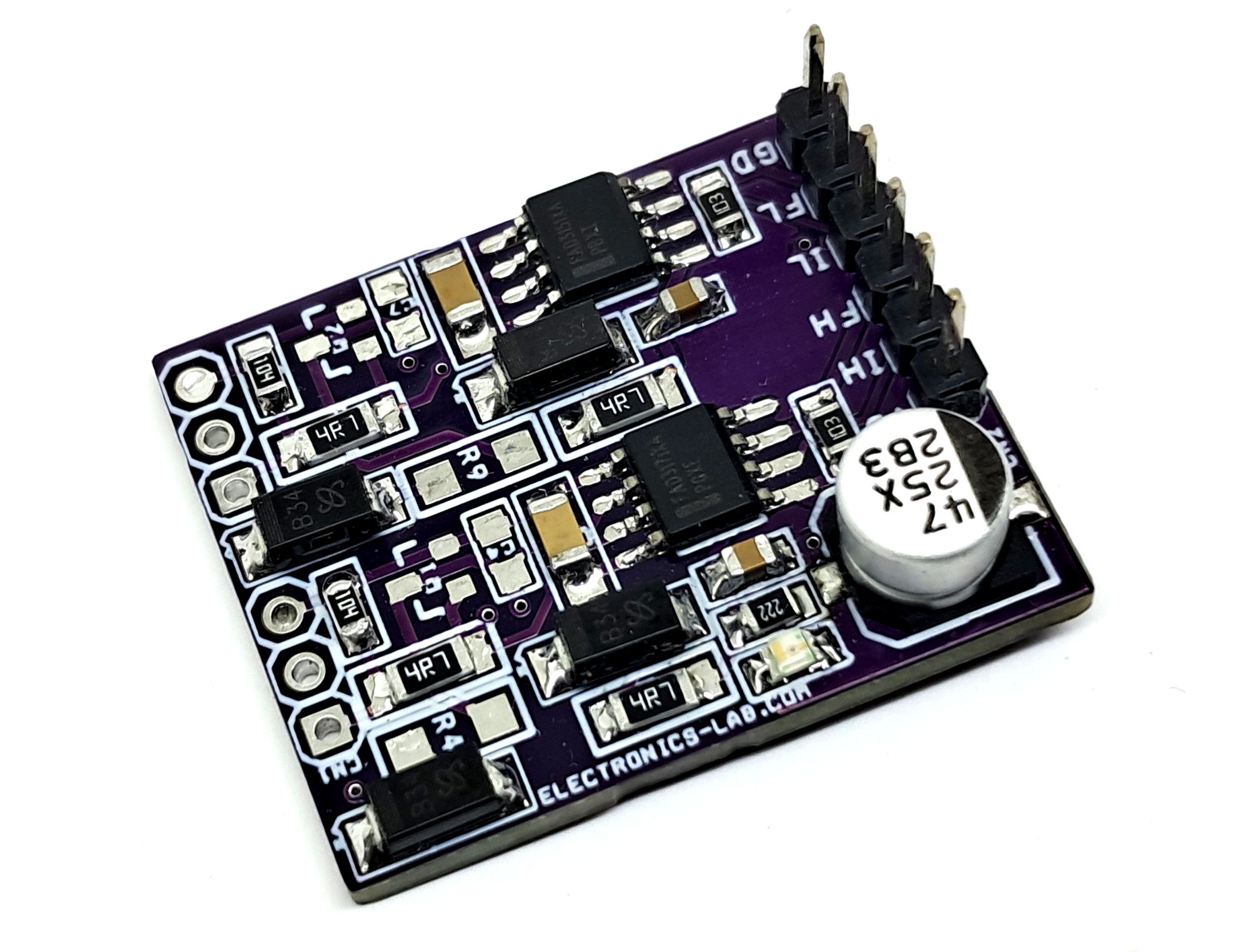
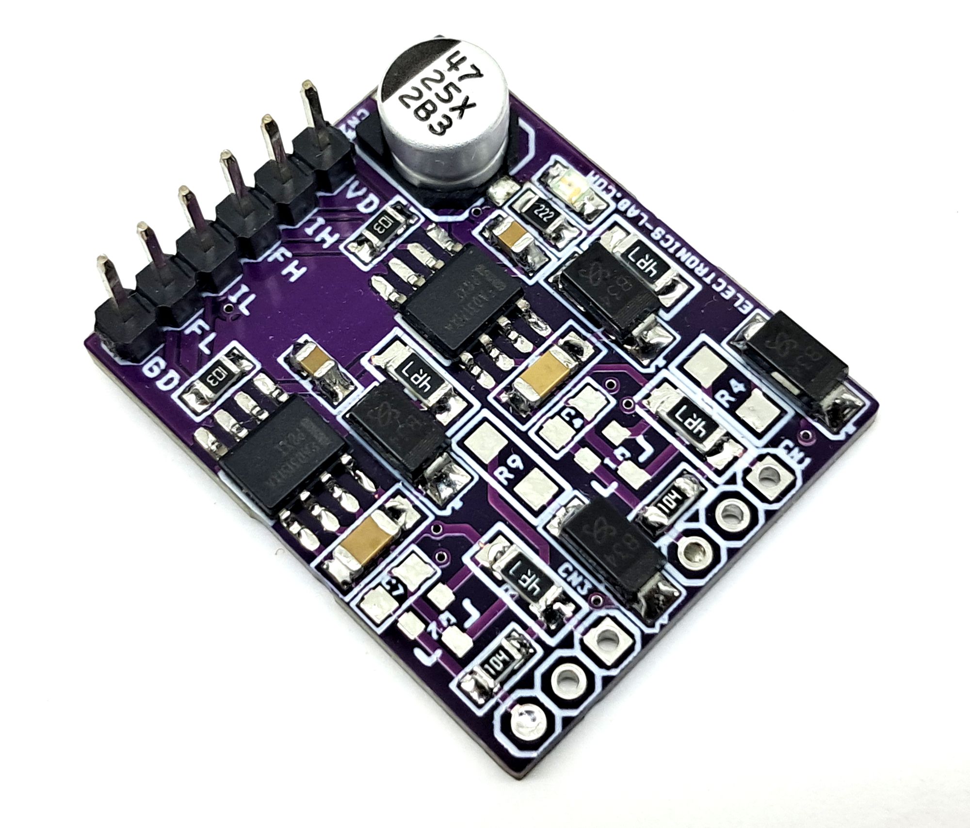
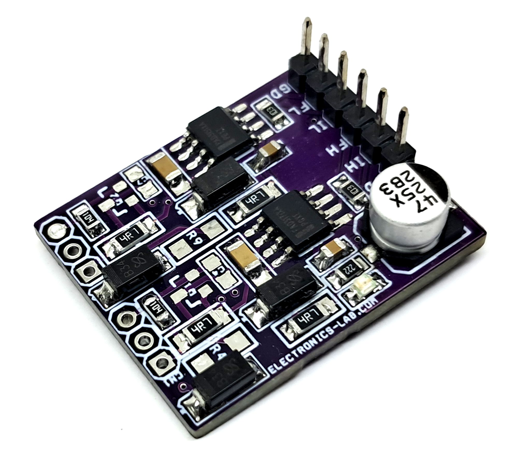
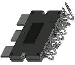
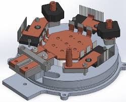
This compact board is designed to drive semi–high current half-bridge power modules such as NXV08A170DB2, specifically for automotive applications. The design is based on the FAD3151 and FAD3171 single-channel floating automotive gate drivers. These devices are suitable for driving high-speed power MOSFETs up to 110V. The gate drivers provide excellent noise immunity against severe negative transients and can tolerate ground offsets up to –80V. The FAD3151 and FAD3171 operate as a complementary pair of ICs to implement a robust half-bridge configuration.
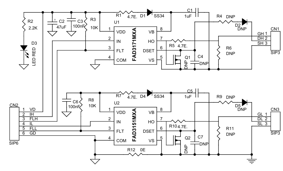
Basic components are populated on the board for testing purposes and to support a standard half-bridge setup. Additional components can be installed depending on the selected MOSFET module and specific application requirements. These optional components enable features such as desaturation protection and Integrated Charge Pump to Support 100% Duty Cycle Operation (FAD3171 Only)
Features
- Power Supply 15V DC
- Single Channel Gate Driver with +/−110 V Floating Vs Capability
- 5A Output Source and Sink Current
- MOSFET Drain−Source Desaturation Detection with Soft Shutdown
- Integrated Charge Pump to Support 100% Duty Cycle Operation (FAD3171 Only)
- Under−voltage Lockout for Both Input Logic and Output Stage
- Bi−directional Fault Reporting Pin
- Header Connector for Input Signals, Fault Output and Logic Power
- High Speed Driver with Short Propagation Delay
- dVs/dt Immune to Min ±50 V/ns
- 3 V and 5 V Input Logic Compatible
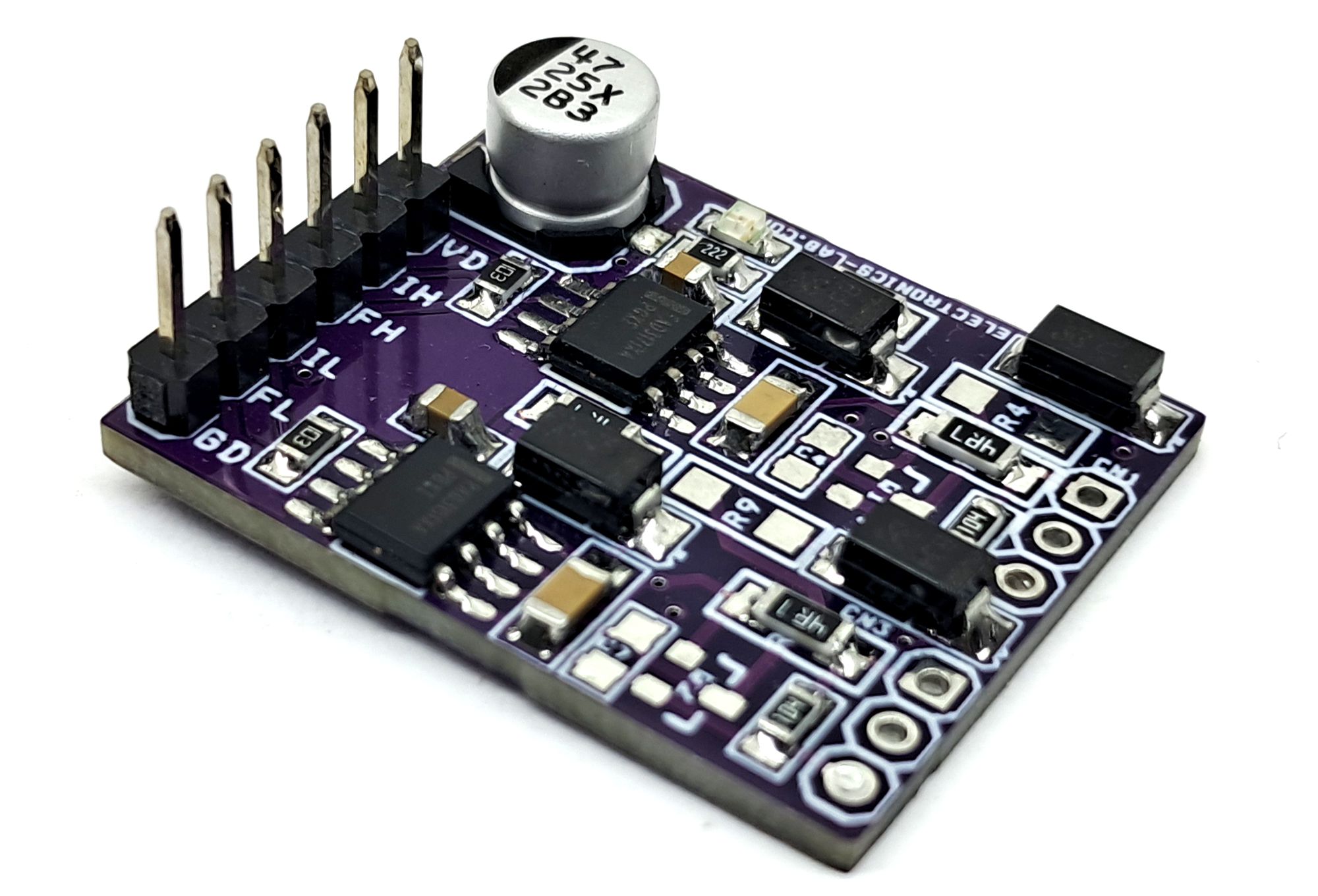
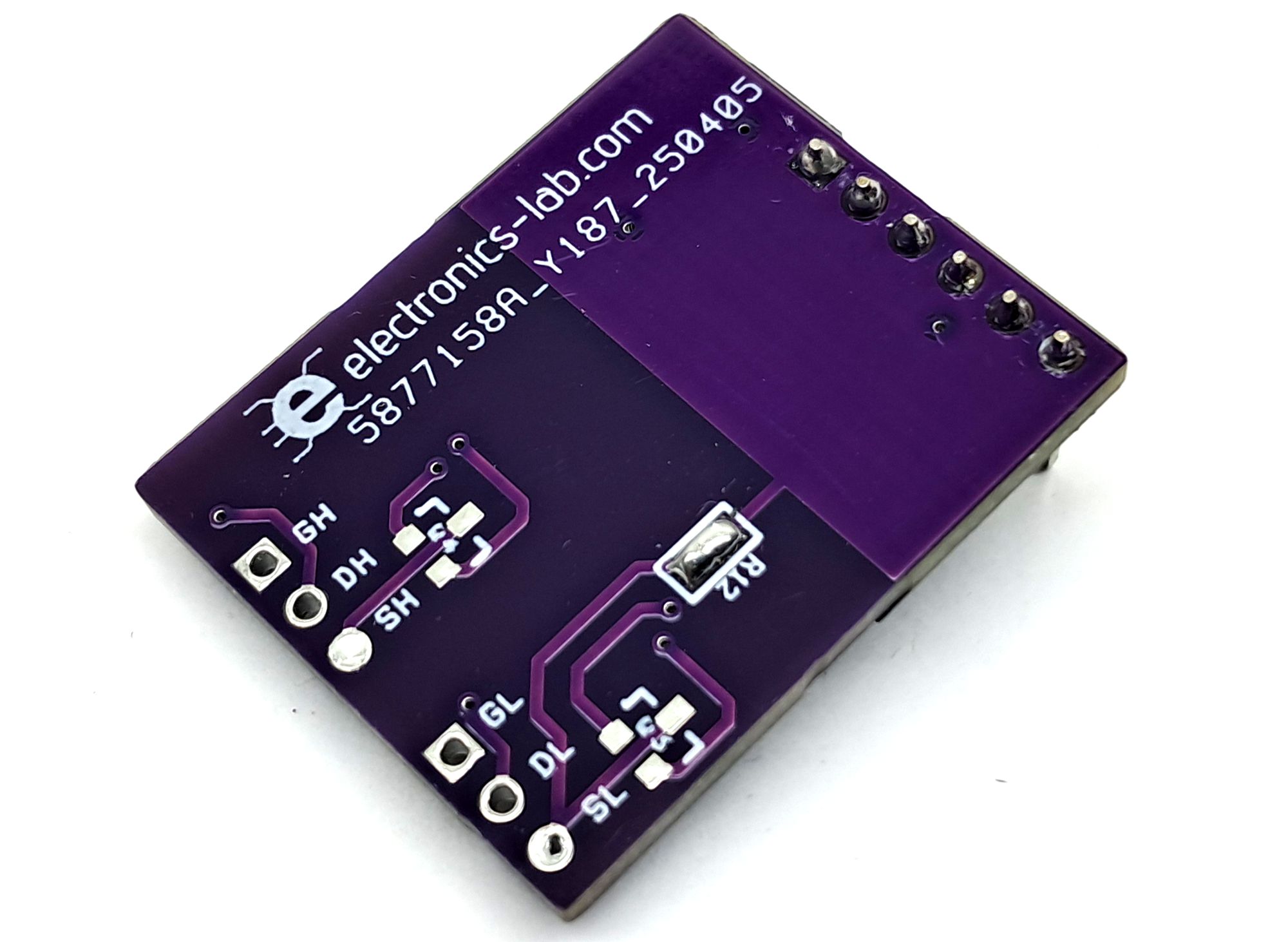
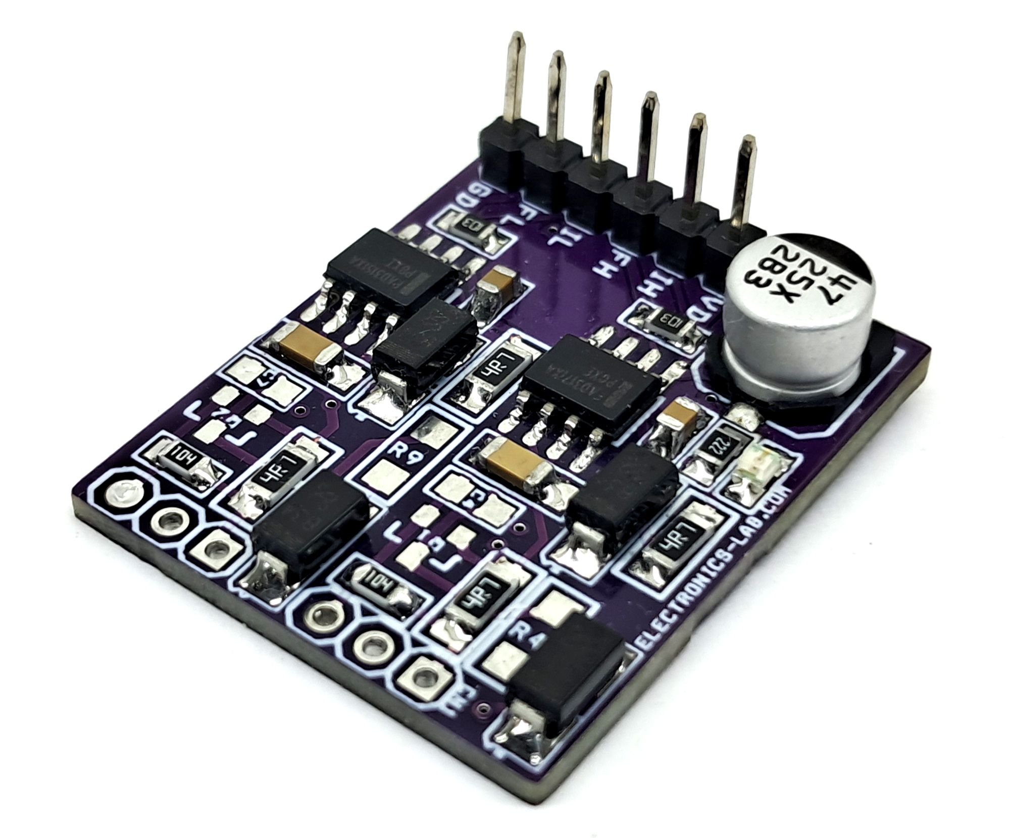
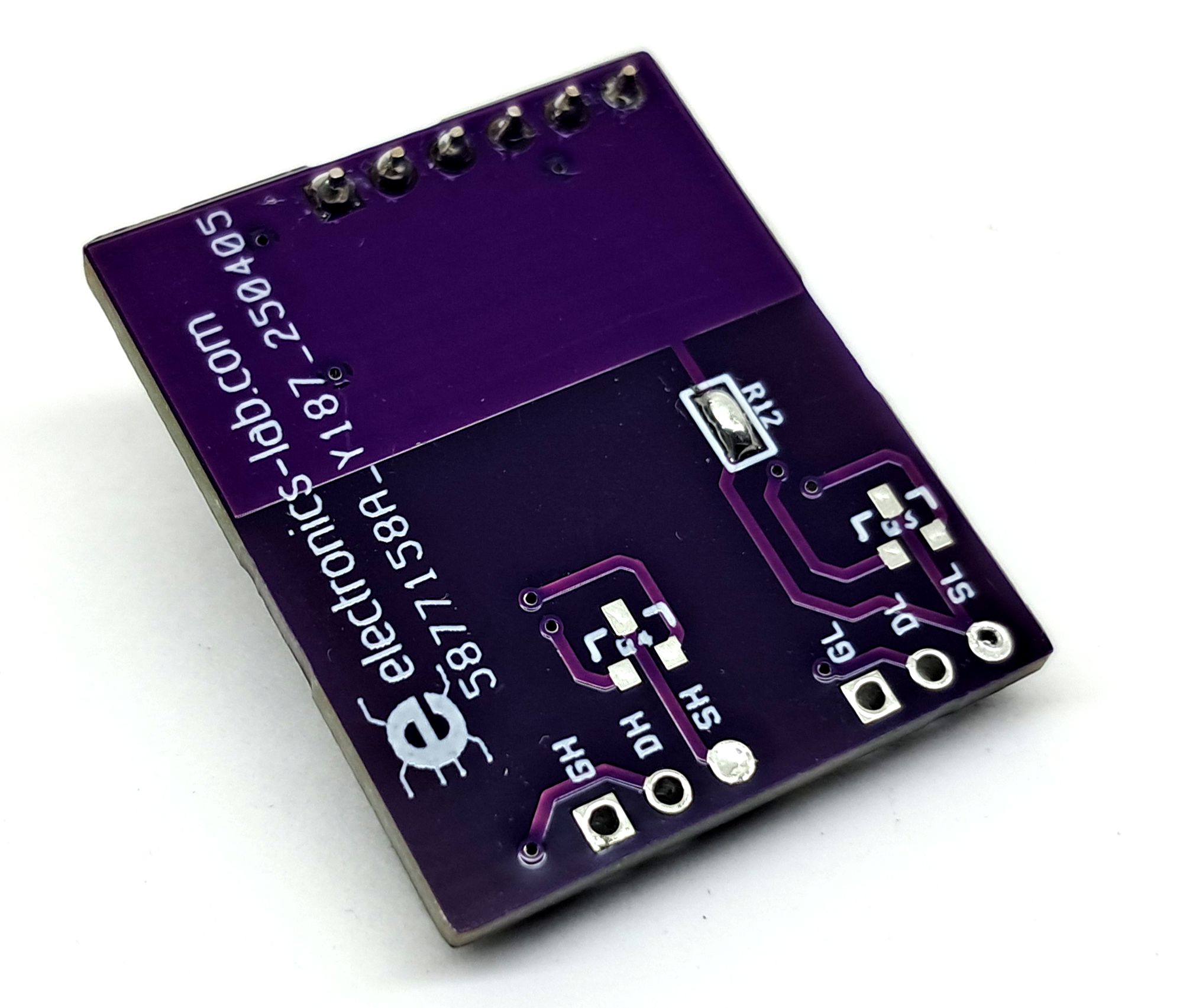
- PCB Dimensions: 29.69 x 24.29 mm
The following components are associated with desaturation protection and full-duty-cycle operation
- R4, R9, D2, D5, R6, R11, C4, C7, Q1, Q2
For detailed design guidance, refer to ON Semiconductor application notes AND90235/D and AND90251-D.
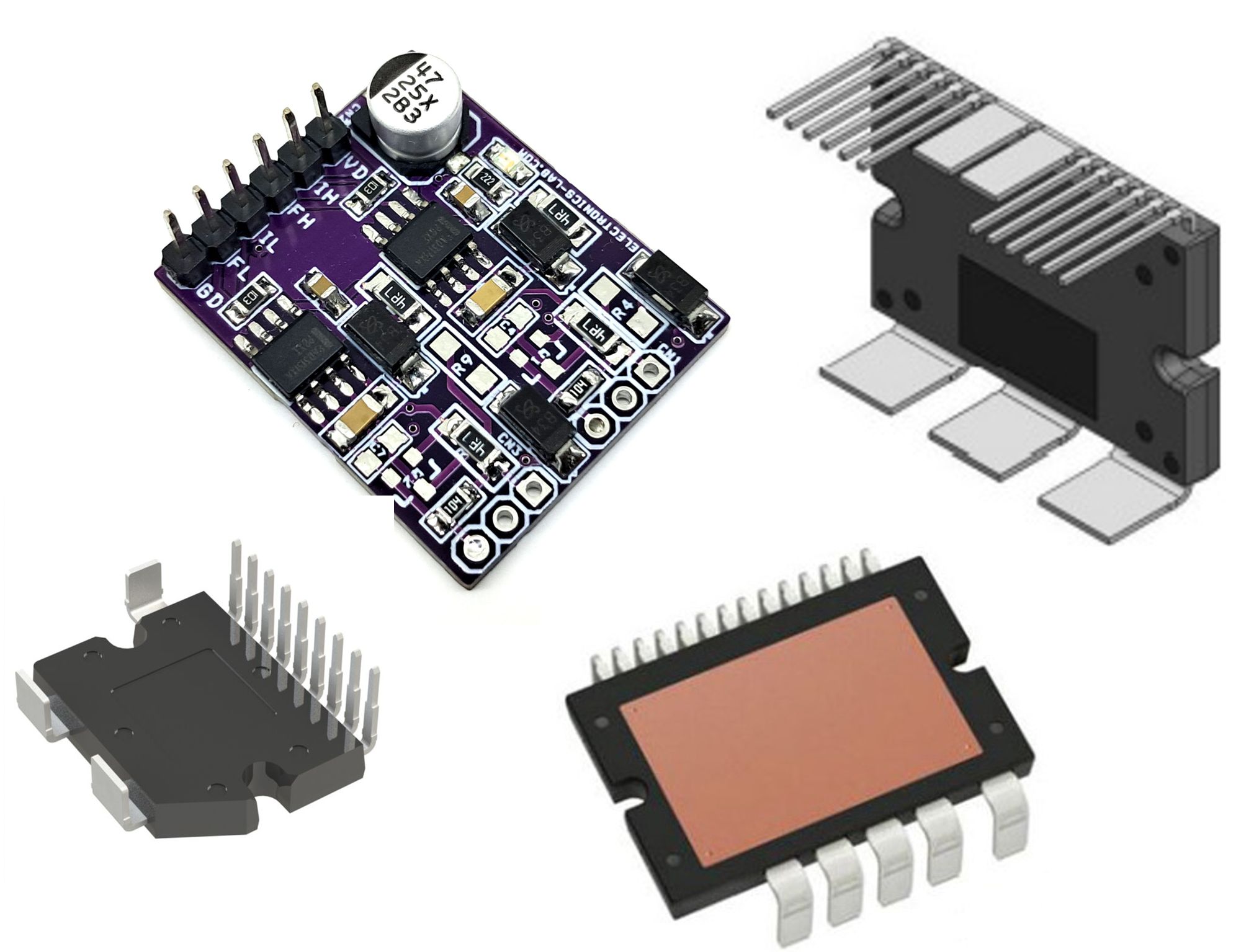
This driver board can interface with various ON Semiconductor half-bridge, H-bridge, and three-phase automotive power modules (typically 48V and 80V systems). A few compatible examples include:
- NXV08A170DB2
- NXV08H250DT1
- NXV08H300DT1
- NXV08H350XT1
- NXV08H400XT2
This makes the board suitable for a wide range of automotive motor control, DC-DC conversion, and high-current switching applications.
Typical Applications
- Gate Driver for 80 V and 100 V MOSFETs and Modules
- 48 V Belt Starter Generator
- 48 V Auxiliary Motor Control (A/C Compressor, e−Turbo, …)
- 48 V Battery Switches
- 48 V DC−DC Converter
- PTC Heaters
- Active DC−Link Discharge Circuits
The FAD3151/3171 drivers have an integrated desaturation detection to protect the power switches during short circuit and over current conditions. The drivers are also equipped with a soft shutdown feature, which initiates a soft shutdown of driver outputs upon desat detection, thus preventing possible overvoltage across power MOSFETs during a heavy−load condition.
The FAD3151/3171 drivers are equipped with bidirectional fault reporting pin that can generate a fault output during desat and under−voltage lockout (UVLO) condition. The bidirectional nature of the fault−reporting pin allows the driver to respond to external fault commands, thereby facilitating fault communication across the system. In addition, the FAD3171 has an integrated charge pump to support 100% duty cycle operation of high side MOSFETs. The gate driver has a desaturation detection circuit that monitors the drain to source voltage VDS of the power MOSFET through the desaturation detection pin.
Connections
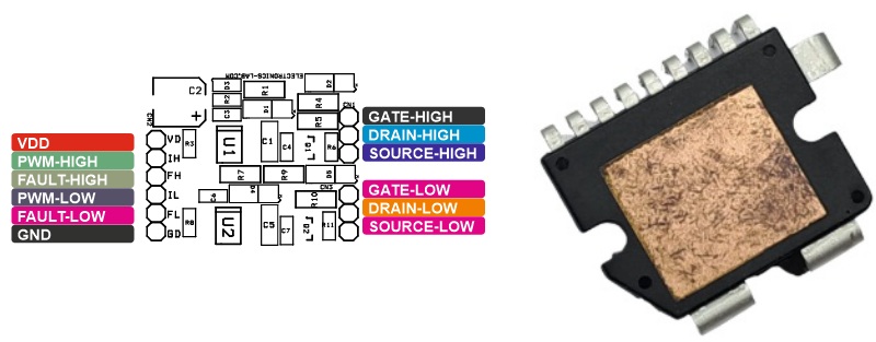
- CN1: Pin 1 = Gate High Side, Pin 2 = Drain High Side, Pin 3 = Source High Side
- CN3: Pin 1 = Gate Low Side, Pin 2 = Drain Low Side, Pin 3 = Source Low Side
- CN2: Pin 1 = VDD 15V DC, Pin 2 = PWM Input High Side, Pin 3 = Fault High Side, Pin 4 = PWM Input Low Side, Pin 5 = Fault Low Side, Pin 6 = GND
- D3: Power LED
Schematic
Parts List
| NO. | QNTY. | DESC. | REF. | MANUFACTURER | SUPPLIER | SUPPLIER PART NO |
|---|---|---|---|---|---|---|
| 1 | 2 | CN1,CN3 | 3 PIN MALE HEADER PITCH 2.54MM | WURTH | DIGIKEY | 732-5316-ND |
| 2 | 1 | CN2 | 6 PIN MALE HEADER PITCH 2.54MM | WURTH | DIGIKEY | 732-5319-ND |
| 3 | 2 | C1,C5 | 1uF/35V CERAMIC SMD SIZE 1206 | YAGEO/MURATA | DIGIKEY | |
| 4 | 1 | C2 | 47uF/25V ELECTROLYITIC | PANASONIC | DIGIKEY | PCE3804CT-ND |
| 5 | 2 | C3,C6 | 100nF/50V CERAMIC SMD SIZE 0805 | YAGEO/MURATA | DIGIKEY | |
| 6 | 10 | Q1,Q2,D2,R4,C4,D5,R6,C7,R9,R11 | DNP | |||
| 7 | 2 | D1,D4 | SS34 SMD DIODE | ONSEMI | DIGIKEY | SS34FSCT-ND |
| 8 | 1 | D3 | LED RED | OSRAM | DIGIKEY | 475-1278-1-ND |
| 9 | 4 | R1,R5,R7,R10 | 4.7E 5% SMD SIZE 1206 | YAGEO/MURATA | DIGIKEY | |
| 10 | 1 | R2 | 2.2K 5% SMD SIZE 0805 | YAGEO/MURATA | DIGIKEY | |
| 11 | 2 | R3,R8 | 10K 5% SMD SIZE 0805 | YAGEO/MURATA | DIGIKEY | |
| 12 | 1 | R12 | 0E | YAGEO/MURATA | DIGIKEY | |
| 13 | 1 | U1 | FAD3171MXA SOIC8 | ONSEMI | DIGIKEY | 488-FAD3171MXACT-ND |
| 14 | 1 | U2 | FAD3151MXA SOIC 8 | ONSEMI | DIGIKEY | 488-FAD3151MXACT-ND |
Connections
Gerber View
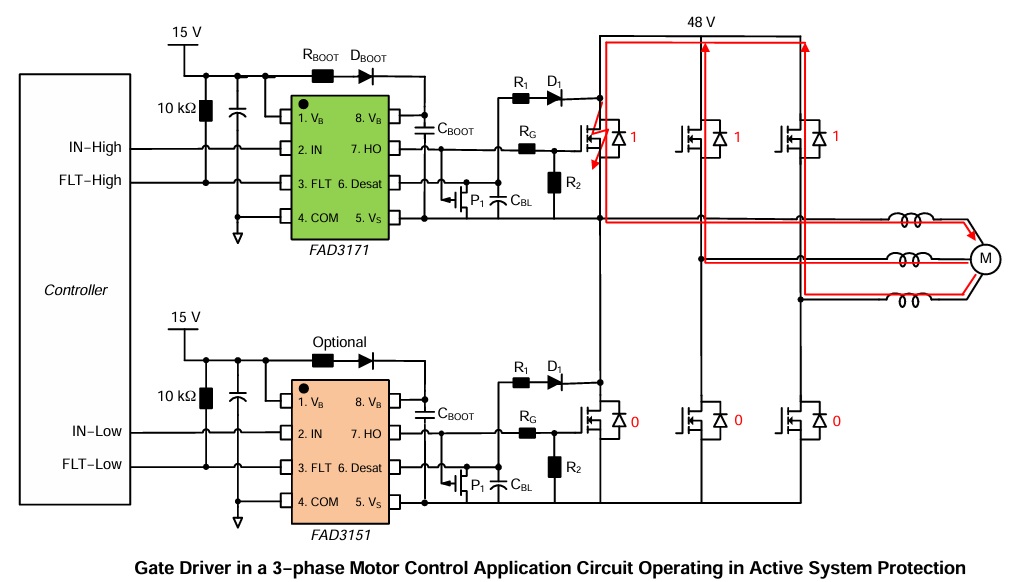
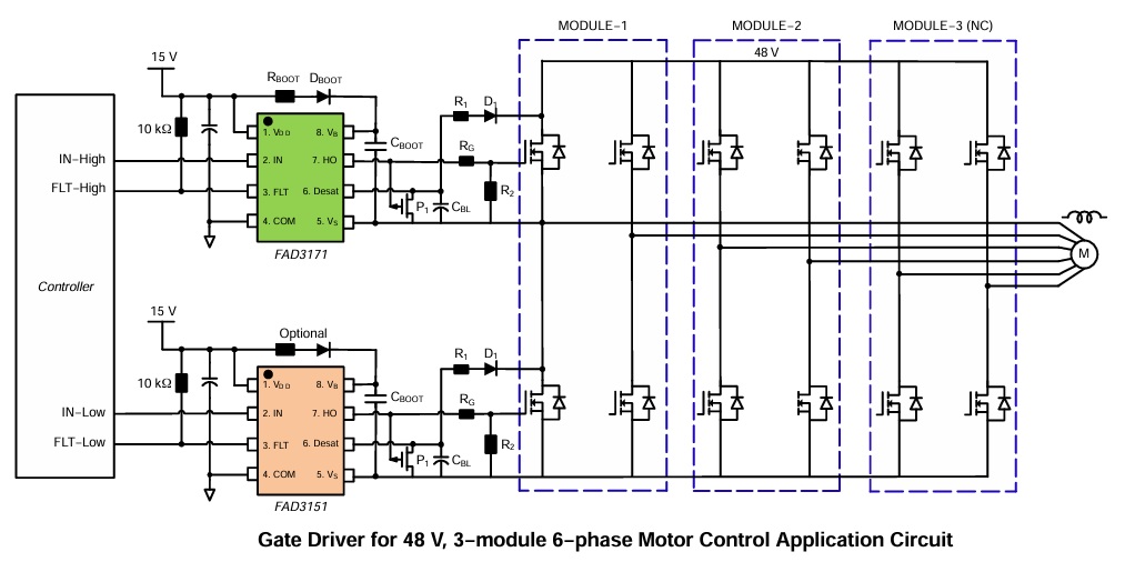
Motor Control Application Diagrams
Microcontroller Connection