4 Channel Optically isolated board with DC-DC converter
This 4-channel optocoupler module uses PC817 chips and a DC-DC converter for electrical isolation. Both high and low-voltage sides have configurable input/output settings.
This is a 4-channel optocoupler module features 4x PC817 optocouplers and an onboard DC-DC converter. It provides reliable electrical isolation between the processor and the high-voltage side. The high-voltage side can be configured as either pull-up or pull-down, while the low-voltage side supports both common-cathode and common-anode configurations. Configuration is selectable via onboard resistors. The integrated 5 V DC-DC converter supplies power to the low-voltage side.
Input Signals
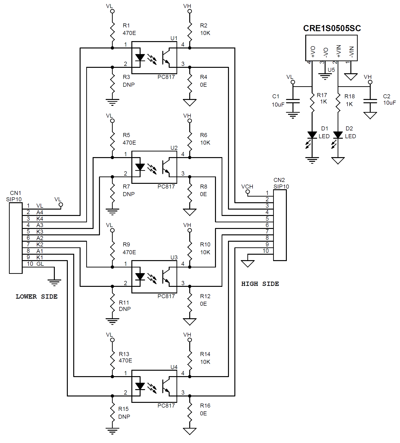
The anodes of the four optocouplers are connected to VCC through current-limiting resistors (R1, R5, R9, R13). The cathodes are left open and can be interfaced with any TTL input signal or switches. For a common cathode configuration, use 0 Ω resistors for R3, R7, R11, and R15, and omit R1, R5, R9, and R13.
Outputs
All optocoupler emitters are connected to the GND output through 0 Ω resistors (R4, R8, R12, R16). Each collector is pulled up using resistors R2, R6, R10, and R14. Under normal conditions, the collector outputs remain high and go low when the corresponding input receives a TTL voltage. For Normally low output configuration use 10K resistors R4, R8, R12, R16 and 0 Ω resistors R2, R6, R10, and R14 in this case use emitter as output.
Features
- Power 5V DC High Side
- Power 5V DC Low side -On Board DC-DC Converter
- 4 Channel Isolated Lines
- Pull-Up Collector or Pull-Down Emitter Selection Using Resistors
- Common Cathode or Common Anode Selection Using Resistor
- Power LED Low Side and High Side
- Header Connector for Inputs and Outputs
- 4 x 3MM Mounting Holes
- PCB Dimensions 47.31 x 23.81 mm
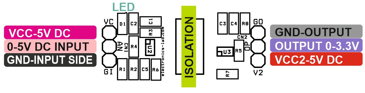
Connections
- CN1: Pin 1 = VCC Low Side, Pin 2 = Anode-4, Pin 3 = Cathode-4, Pin 4 = Anode-3, Pin 5 = Cathode-3, Pin 6 = Anode-2, Pin 7 = Cathode-2, Pin 8 = Anode-1, Pin 9 = Cathode-1, Pin 10 = GND/Low Side
- CN2: Pin 1 = VCC/High Side, Pin 2 = Collector-4, Pin 3 = Emitter-4, Pin 4 = Collector-3, Pin 5 = Emitter-3, Pin 6 = Collector-2, Pin 7 = Emitter-2, Pin 8 = Collector-1, Pin 9 = Emitter-1, Pin 10= GND/High Side
- D1: Low Side Power LED (DC-DC Output)
- D2: High Side Power LED (DC-DC Input)
Schematic
Parts List
| NO. | QNTY. | REF. | DESC. | MANUFACTURER | SUPPLIER | SUPPLIER PART NO |
|---|---|---|---|---|---|---|
| 1 | 2 | CN1,CN2 | 10 PIN MALE HEADER PITCH 2.54MM | WURTH | DIGIKEY | 732-2670-ND |
| 2 | 2 | C1,C2 | 10uF/10V-25V CERAMIC SMD SIZE 0805 | YAGEO/MURATA | DIGIKEY | |
| 3 | 2 | D1,D2 | LED RED SMD SIZE 0805 | OSRAM | DIGIKEY | 475-1278-1-ND |
| 4 | 4 | R1,R5,R9,R13 | 470E 5% SMD SIZE 0805 | YAGEO/MURATA | DIGIKEY | |
| 5 | 4 | R2,R6,R10,R14 | 10K 5% SMD SIZE 0805 | YAGEO/MURATA | DIGIKEY | |
| 6 | 4 | R3,R7,R11,R15 | DNP | |||
| 7 | 4 | R4,R8,R12,R16 | 0E 5% SMD SIZE 0805 | YAGEO/MURATA | DIGIKEY | |
| 8 | 2 | R17,R18 | 1K 5% SMD SIZE 0805 | YAGEO/MURATA | DIGIKEY | |
| 9 | 4 | U1,U2,U3,U4 | PC817 DIP4 | SHARP | DIGIKEY | PC817X2NSZ9F-ND |
| 10 | 1 | U5 | CRE1S0505SC | MURATA | DIGIKEY | 811-3196-ND |
Connections
Gerber View
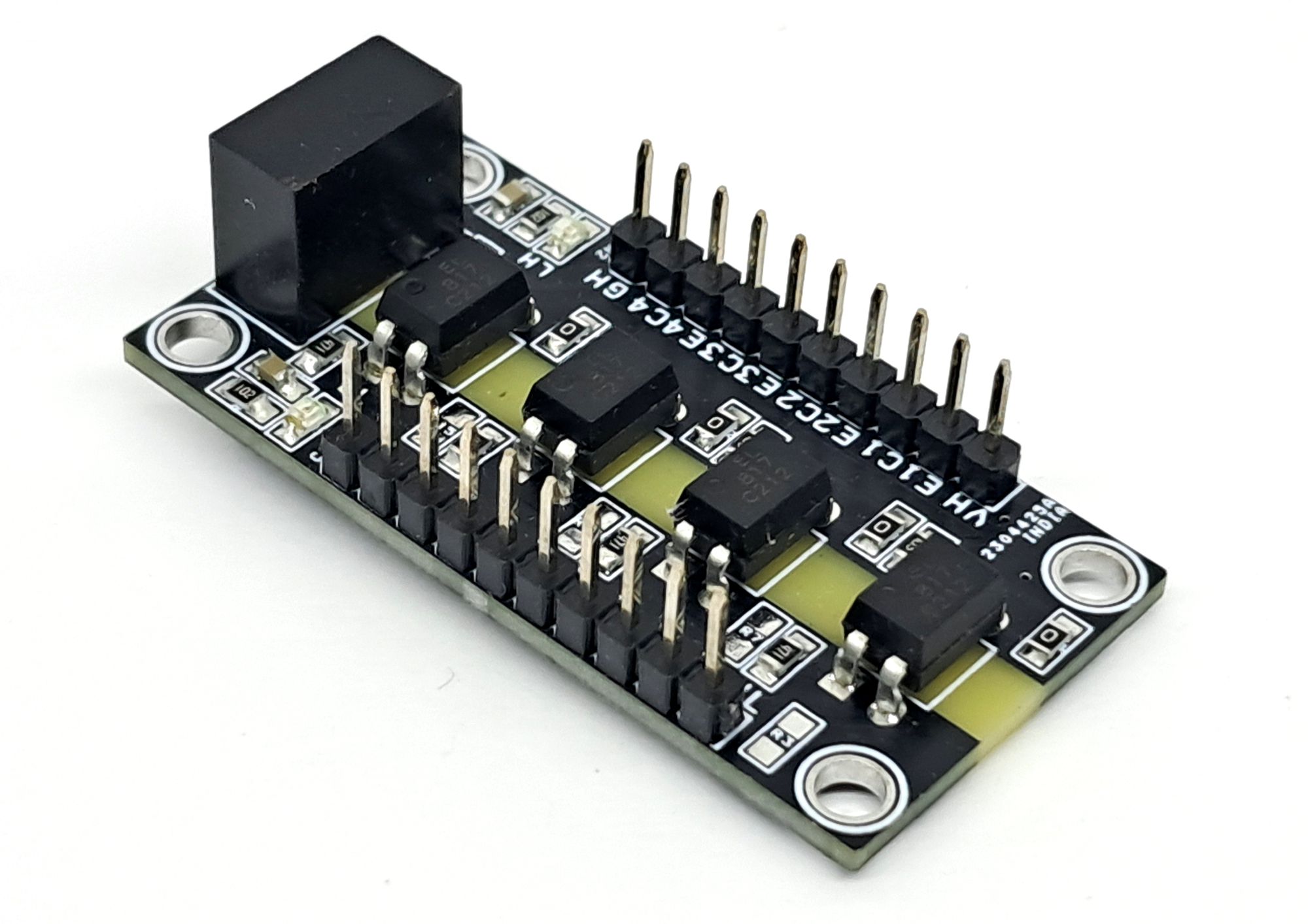
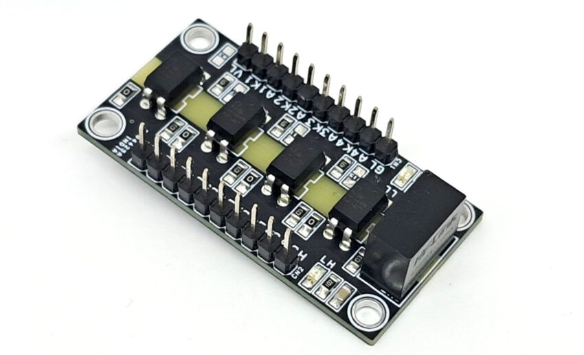
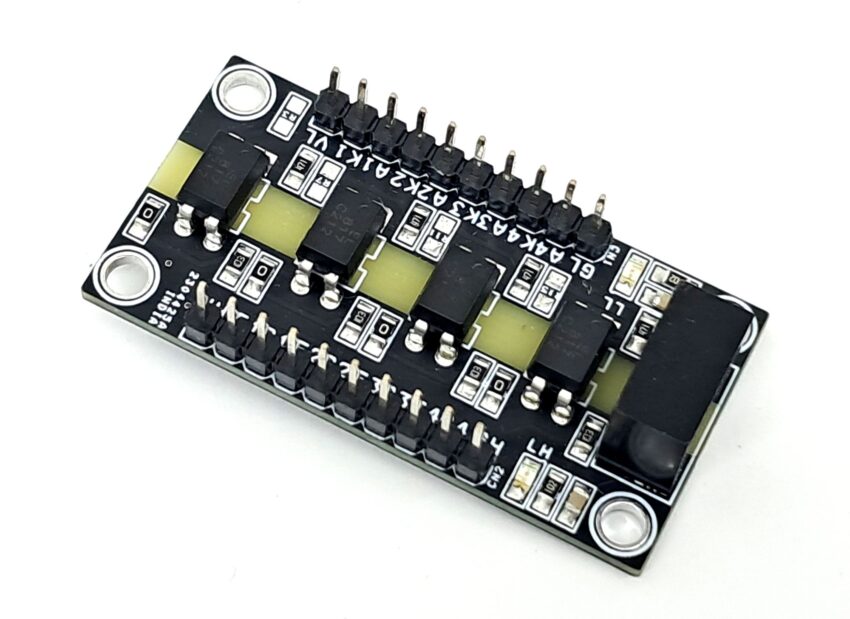
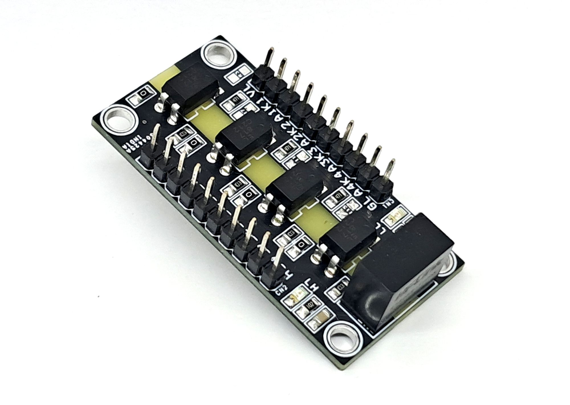
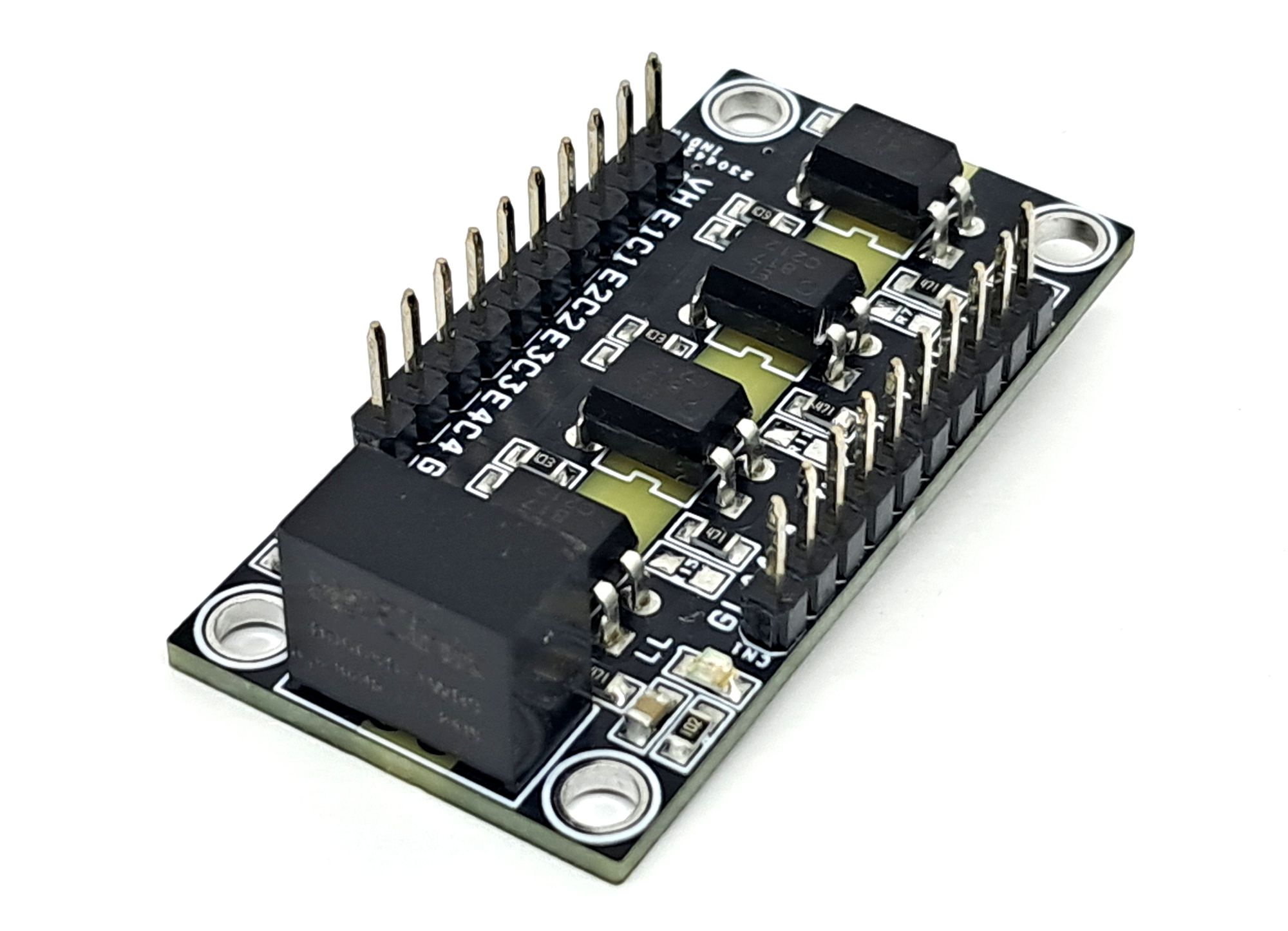
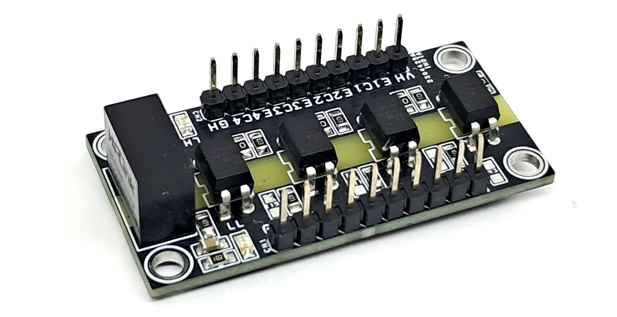
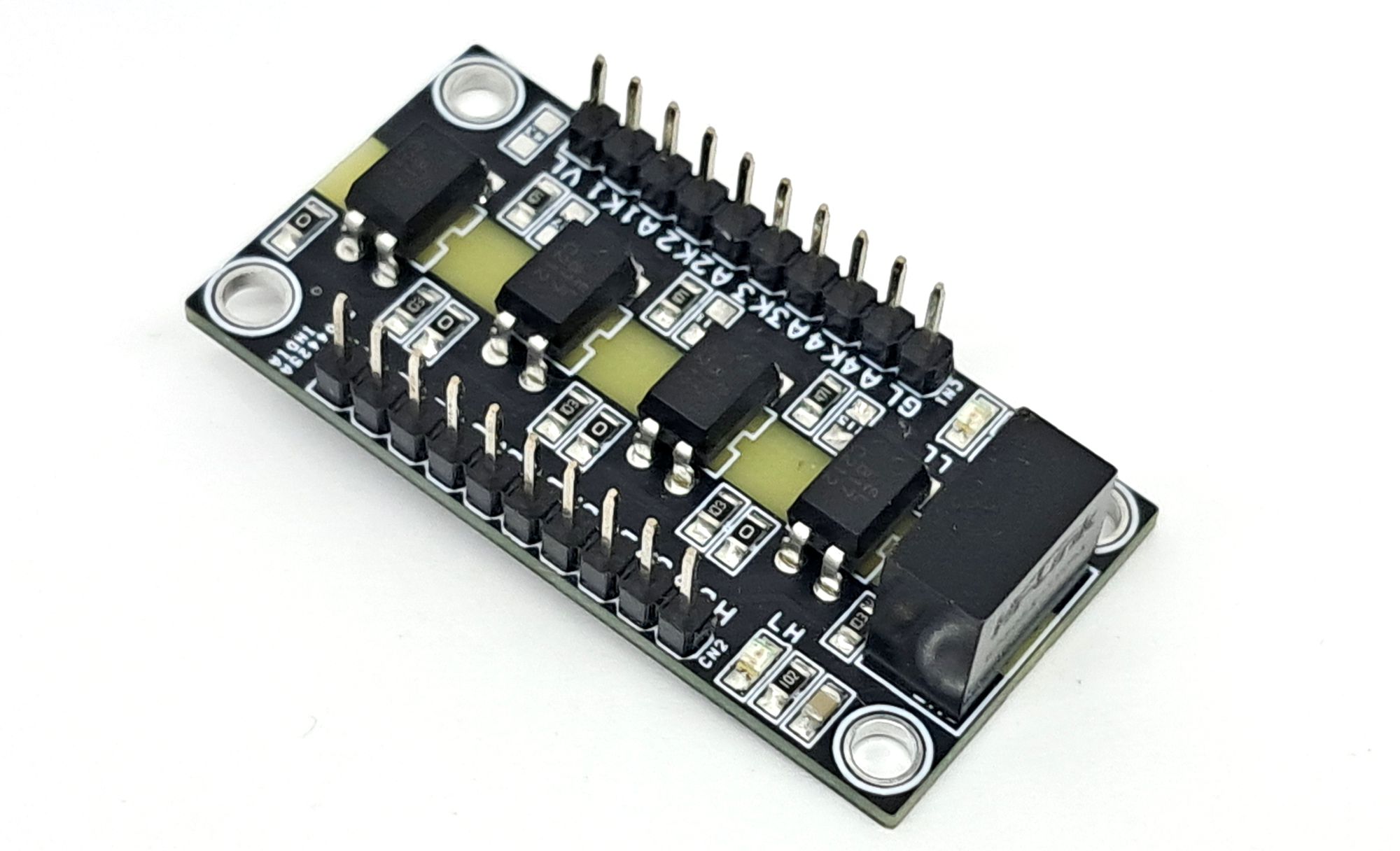
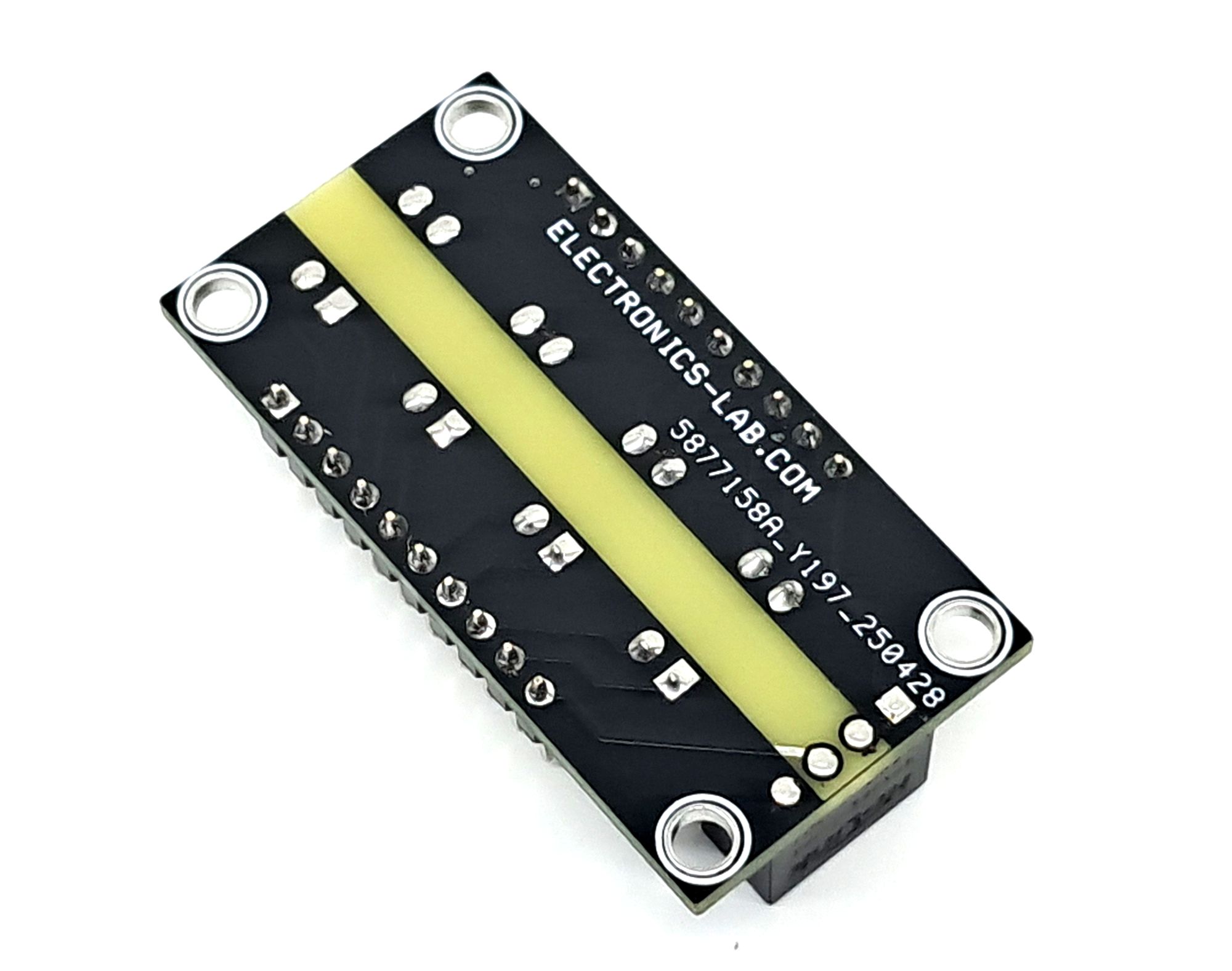
Photos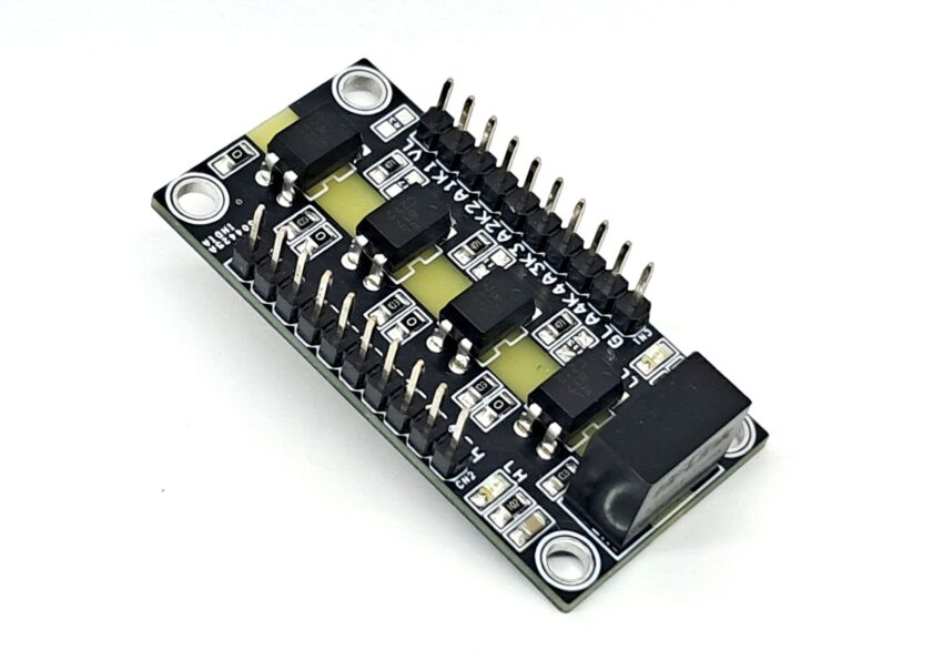


the connection diagram looks different to the board layout. why???