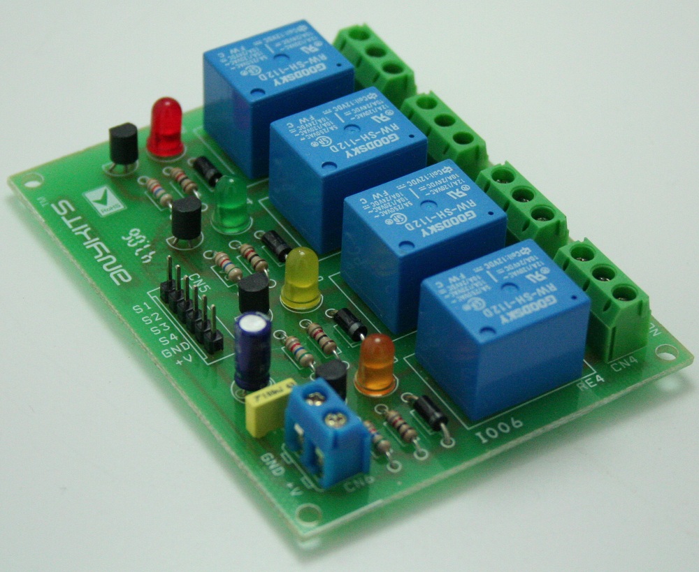
4 Channel Relay Board
Quad Channel Relay Board is a simple and convenient way to interface 4 relays for switching application in your project. Features Input supply 12 VDC @ 170 mA Output four SPDT relay Relay specification 5 A @ 230 VAC Trigger level 2 ~ 5 VDC Berg pins for connecting power and trigger voltage LED on each channel indicates relay status Power Battery Terminal (PBT) for easy relay output and aux power connection Four mounting holes of 3.2 mm each PCB dimensions 88 mm x 68 mm Applications: Robotics, Electronics projects, Industrial controls, Microwaves Oven, Fans, DC Motor, AC Lamp, Solenoids Remote Controls etc.
Quad Channel Relay Board is a simple and convenient way to interface 4 relays for switching application in your project.
Features
- Input supply 12 VDC @ 170 mA
- Output four SPDT relay
- Relay specification 5 A @ 230 VAC
- Trigger level 2 ~ 5 VDC
- Berg pins for connecting power and trigger voltage
- LED on each channel indicates relay status
- Power Battery Terminal (PBT) for easy relay output and aux power connection
- Four mounting holes of 3.2 mm each
- PCB dimensions 88 mm x 68 mm
Applications: Robotics, Electronics projects, Industrial controls, Microwaves Oven, Fans, DC Motor, AC Lamp, Solenoids Remote Controls etc.
Relay Load (Contact Capacity of Relay)
- 7 A @ 230-250 VAC
- 10 A @ 120 VAC
- 10 A @ 24 VDC
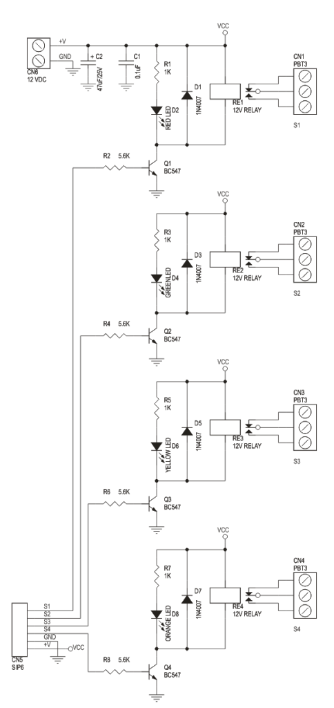
- CN1 – CN4 Connector : Relay 1 to 4 (S1 to S4) Output (Normally Open/Normally Close)
- CN5 Connector : Control Signal Input, Trigger 2 to 5 VDC and Supply Input 12 VDC
- D2,D4,D6,D8 : Relay On/Off LED Indication
- CN6 Connector : Axillary Supply 12 VDC
Schematic
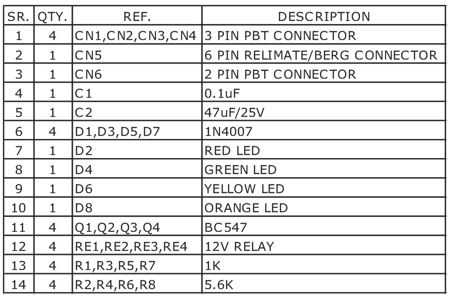
Parts List
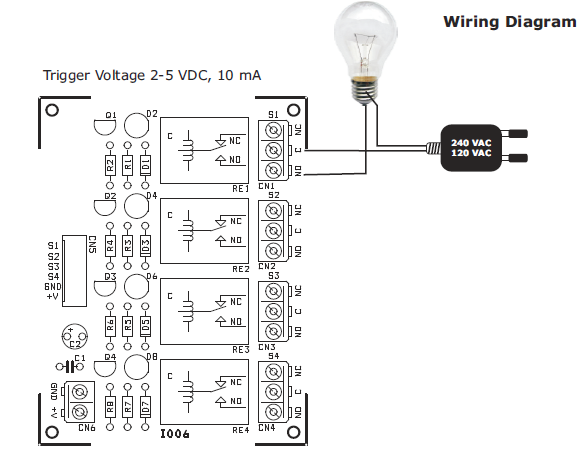
Connection
Dear sir, i am making 4-channel relay board . but during making i have a problem with capacitor (like which type of capacitor is ? and how many volts ?). i want to know the capacitor detail used in 4-channel relay board .plz help me…
If you are reffering to C1, then a simple ceramic capacitor will do it’s job.
Can you explain why the capacitors? I found no relay module on the market that uses a capacitor.What is the need for it?
The capacitors are used for noise filtering of the power supply. If you use a filtered power supply you may omit them.
Hi,please provide the Gerber file
As requested, I’ve uploaded Gerber files above. Thanks
Sir can i use 5v relay instead of 12v with the same
Yes, you can use 5V relays with 5V input.
there is no connection detail for vcc and gnd for any nodemacu or arduino connection
You can interface any microcontroller board through the CN5 connector. What’s your point?
which software you have used
The board has been designed with Cadence Orcad.
How to connect the board to arduino uno.
No details for VCC and gnd for any arduino boards
How to connect the relay board with 12 v connection and then with the arduino uno.
Pls help me out.
Sir,,what if we want to build,some like this,but used relay,,anyway i need the out put is lamp and bell,,but,just one switch may turn on first and the other is off..it seems like quiz..please made some like that.Thanks
Sorry, i don’t understand your question. Please better explain.
sir can i ask, what is that SIP6, and CN?
SIP6 is a 6 pin connector as shown in photos and CN is the connector name, CN1, CN2 etc
Sir please tell me I won’t to operate this pcb in 12v but after give supply then S1s2s3s4 which link I give GND ro +v
Sir this circuit 24 hor going to work but I won’t to ask you there is possible to work
hello and thank you
how if i want it without led ?
just remove led with 1k resistor?
Hi, I have a question please answer me. I bought components but I didn’t get what to do with this board. I don’t have an Arduino how can I connect it to bulb like you showed? what tool should i buy to make the connection with bulb?
Bulbs can be connected to the output of the relays. NEUTRAL from the mains goes to the bulb directly and LIVE goes to the C of the connector. Then NO goes to the other end of the bulb. This is like the diagram above.
Hi sir I want to connect two 2 channel relays. How should I do it.
Sir can i use 3v relay instead of 12v with the same