Continuous Conduction Mode Pre-Converters Module for Power Factor Controller
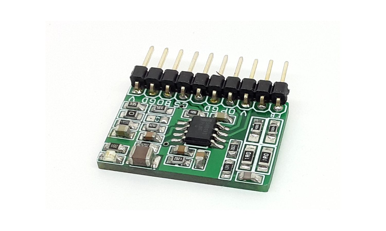
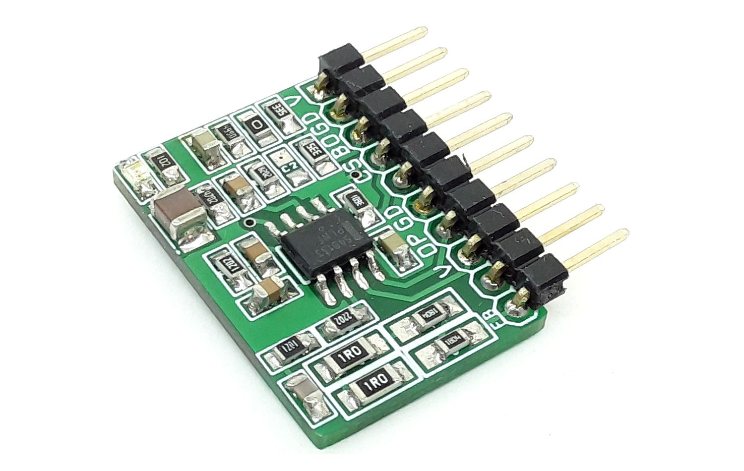
This compact module shown here is a Continuous Conduction Mode (CCM) Power Factor Correction Step up Pre-Converter. All-important inputs and output pins are broken out for use in your application, making this board hackable!
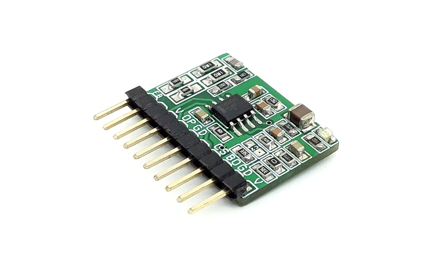
This compact module shown here is a Continuous Conduction Mode (CCM) Power Factor Correction Step up Pre-Converter. All-important inputs and output pins are broken out for use in your application, making this board hackable! Please refer to the datasheet of the NCP1654 chip for easy alteration and configuration of the board as per requirements. This board controls the power switch conduction time (PWM) in fixed frequency mode and is dependent on the instantaneous coil current. This module drastically simplifies the PFC implementation scheme. It also integrates high safety features that make the NCP1654 module ideal for robust and compact PFC stages like an effective input power runaway clamping circuit. Please refer to the application schematic to create a powerful PFC using this pre-driver module. The chip is available with various options for frequency such as 65Khz, 133Khz, and 200Khz. Choose the appropriate chip as per frequency requirement This project is tested with a 65Khz oscillator chip.
Features
- Supply 15V DC
- ±1.5 A Totem Pole Gate Drive, can drive TO247 and TO220 MOSFETS
- Average Current Continuous Conduction Mode
- Fast Transient Response
- Very Few External Components
- Very Low Startup Currents (< 75 uA)
- Very Low Shutdown Currents (< 400 uA)
- Low Operating Consumption
- Accurate Fully Integrated 65
- Latching PWM for cycle−by−cycle Duty−Cycle Control
- Internally Trimmed Internal Reference
- Undervoltage Lockout with Hysteresis
- Soft−Start for Smoothly Startup Operation
- Shutdown Function
- PCB Dimensions 26.04 x 17.94mm
Safety Features
- Inrush Current Detection
- Overvoltage Protection
- Undervoltage Detection for Open Loop Detection or Shutdown
- Brown−Out Detection
- Soft−Start
- Accurate Overcurrent Limitation
- Overpower Limitation
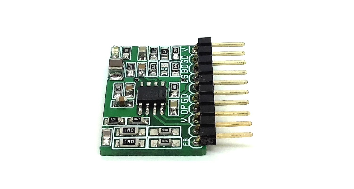
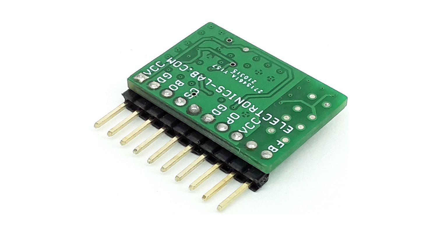
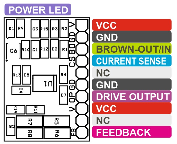
Connections Connector CN1
- Pin 1 = VCC 15V DC, Pin 2 = GND, Pin 3 = BO Brown-Out/IN, Pin 4 = CS, Pin 5 = NC, Pin 6 = GND, Pin 7 = Output (MOSFET Gate), Pin 8 = VCC 15V DC, Pin 9 = NC, Pin 10 = FB/Feedback Voltage
- D1 Power LED
VCC
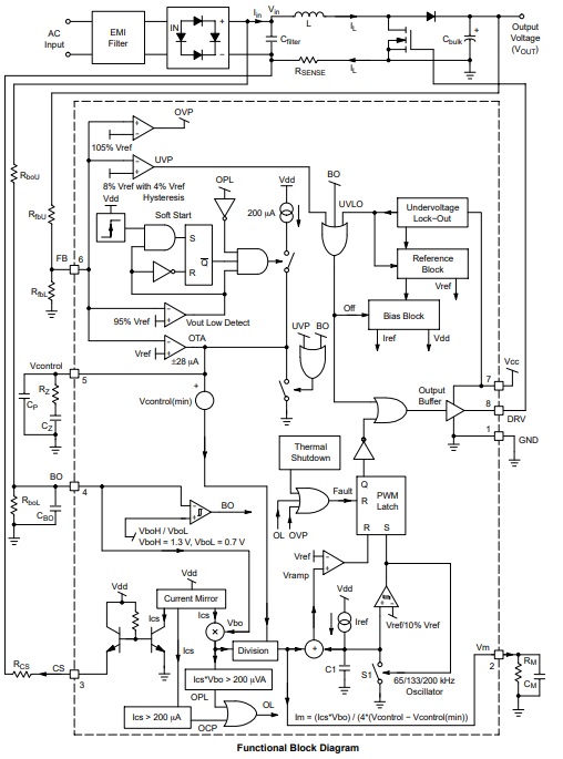
This pin is the positive supply of the IC. The circuit typically starts to operate when VCC exceeds 10.5 V and turns off when VCC goes below 9 V. After start−up, the operating range is 9 V up to 20 V.
CS (Current Sense)
This pin sources a current ICS which is proportional to the inductor current IL. The sense current ICS is for overcurrent protection (OCP), overpower limitation (OPL) and PFC duty cycle modulation. When ICS goes above 200 uA, OCP is activated and the Drive Output is disabled.
BO (VBO) Brow-Out/In
BO pin detects a voltage signal proportional to the average input voltage. When VBO goes below VBOL, the circuit that detects too low input voltage conditions (brown−out), turns off the output driver and keeps it in low state until VBO exceeds VBOH. This signal which is proportional to the RMS input voltage Vac is also for overpower limitation (OPL) and PFC duty cycle modulation.
VFB (Voltage Feedback/Shutdown)
This pin receives a feedback signal VFB that is proportional to the PFC circuit’s output voltage. This information is used for both output regulation, overvoltage protection (OVP), and output Undervoltage protection (UVP) to protect the system from damage at feedback abnormal situations. When VFB goes above 105% VREF, OVP is activated and the Drive Output is disabled. When VFB goes below 8% VREF, the device enters a low−consumption shutdown mode.
OP (Drive Output)
The high current capability of the totem pole gate drive (±1.5 A) makes it suitable to effectively drive high gate charge power MOSFET
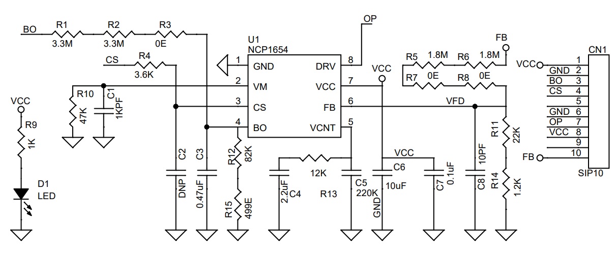
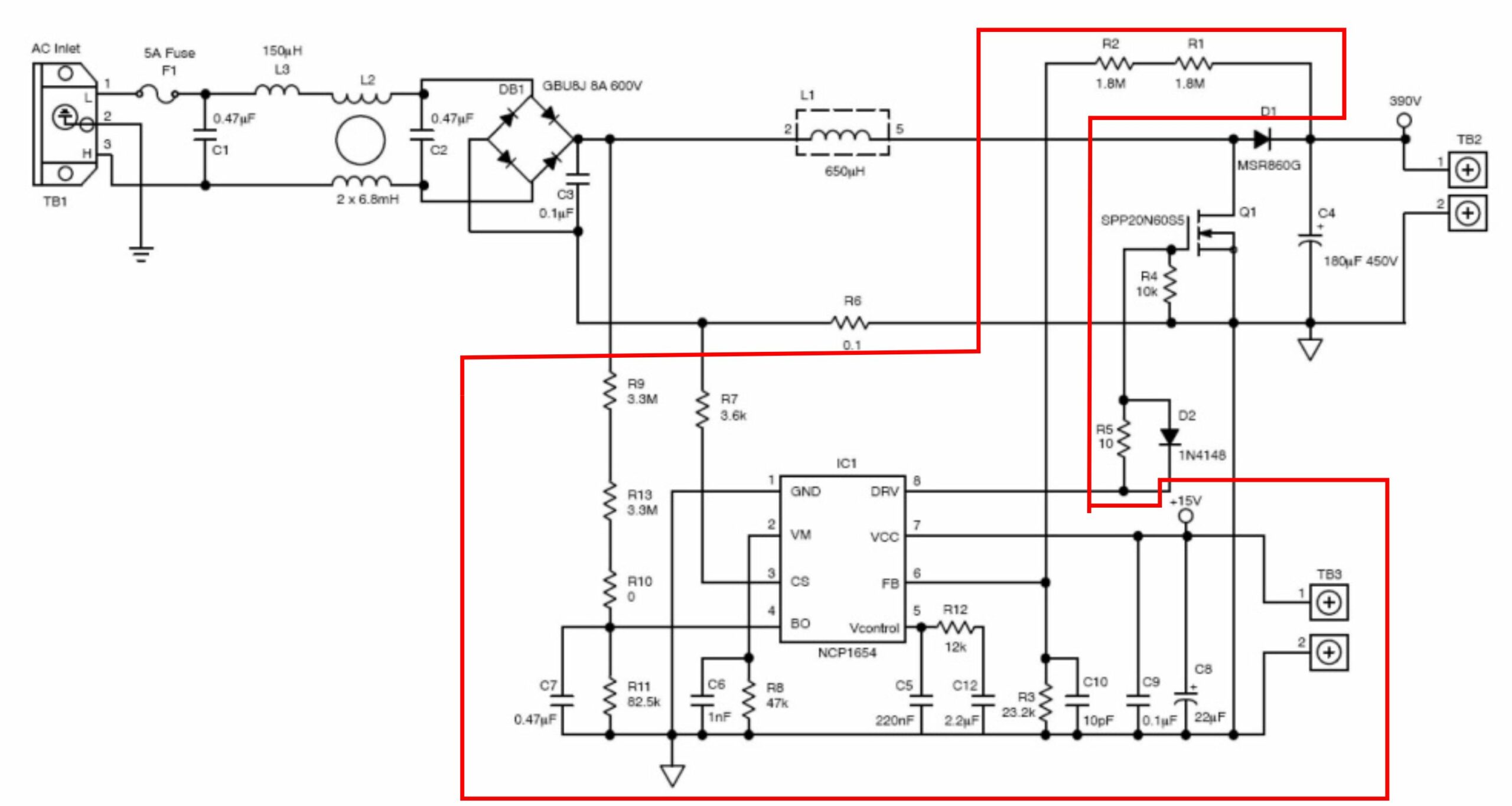
Schematic
Parts List
| NO. | QNTY. | REF. | DESC. | MANUFACTURER | SUPPLIER | SUPPLIER'S PART NO |
|---|---|---|---|---|---|---|
| 1 | 1 | CN1 | 10 PIN MALE HEADER RIGHT ANGLE PITCH 2.54MM | WURTH | DIGIKEY | 732-2670-ND |
| 2 | 1 | C1 | 1KPF(1nF)/50V CERAMIC SMD SIZE 0805 | YAGEO/MURATA | DIGIKEY | |
| 3 | 1 | C2 | DNP | |||
| 4 | 1 | C3 | 0.47uF/50V CERAMIC SMD SIZE 0805 | YAGEO/MURATA | DIGIKEY | |
| 5 | 1 | C4 | 2.2uF/50V CERAMIC SMD SIZE 0805 | YAGEO/MURATA | DIGIKEY | |
| 6 | 1 | C5 | 220KF(0.22uF)/50V CERAMIC SMD SIZE 0805 | YAGEO/MURATA | DIGIKEY | |
| 7 | 1 | C6 | 10uF/25V CERAMIC SMD SIZE 1210 OR 1206 | YAGEO/MURATA | DIGIKEY | |
| 8 | 1 | C7 | 0.1uF/50V CERAMIC SMD SIZE 0805 | YAGEO/MURATA | DIGIKEY | |
| 9 | 1 | C8 | 10PF/50V CERAMIC SMD SIZE 0805 | YAGEO/MURATA | DIGIKEY | |
| 10 | 1 | D1 | LED RED SMD SIZE 0805 | OSRAM | DIGIKEY | 475-1278-1-ND |
| 11 | 2 | R1,R2 | 3.3M 5% SMD SIZE 0805 | YAGEO/MURATA | DIGIKEY | |
| 12 | 2 | R7,R8 | 0E SMD SIZE 1206 | YAGEO/MURATA | DIGIKEY | |
| 13 | 1 | R4 | 3.6K 1% SMD SIZE 0805 | YAGEO/MURATA | DIGIKEY | |
| 14 | 2 | R5,R6 | 1.8M 5% SMD SIZE 1206 | YAGEO/MURATA | DIGIKEY | |
| 15 | 1 | R9 | 1K 5% SMD SIZE 0805 | YAGEO/MURATA | DIGIKEY | |
| 16 | 1 | R10 | 47K 5% SMD SIZE 0805 | YAGEO/MURATA | DIGIKEY | |
| 17 | 1 | R11 | 22K 5% SMD SIZE 0805 | YAGEO/MURATA | DIGIKEY | |
| 18 | 1 | R12 | 82K 1% SMD SIZE 0805 | YAGEO/MURATA | DIGIKEY | |
| 19 | 1 | R13 | 12K 5% SMD SIZE 0805 | YAGEO/MURATA | DIGIKEY | |
| 20 | 1 | R14 | 1.2K 5% SMD SIZE 0805 | YAGEO/MURATA | DIGIKEY | |
| 21 | 1 | R15 | 499E 1% SMD SIZE 0805 | YAGEO/MURATA | DIGIKEY | |
| 22 | 1 | U1 | NCP1654BD65R2G | ONSEMI | DIGIKEY | NCP1654BD65R2GOSCT-ND |
| 23 | 1 | R3 | 0E SMD SIZE 0805 | YAGEO/MURATA | DIGIKEY |
Connections
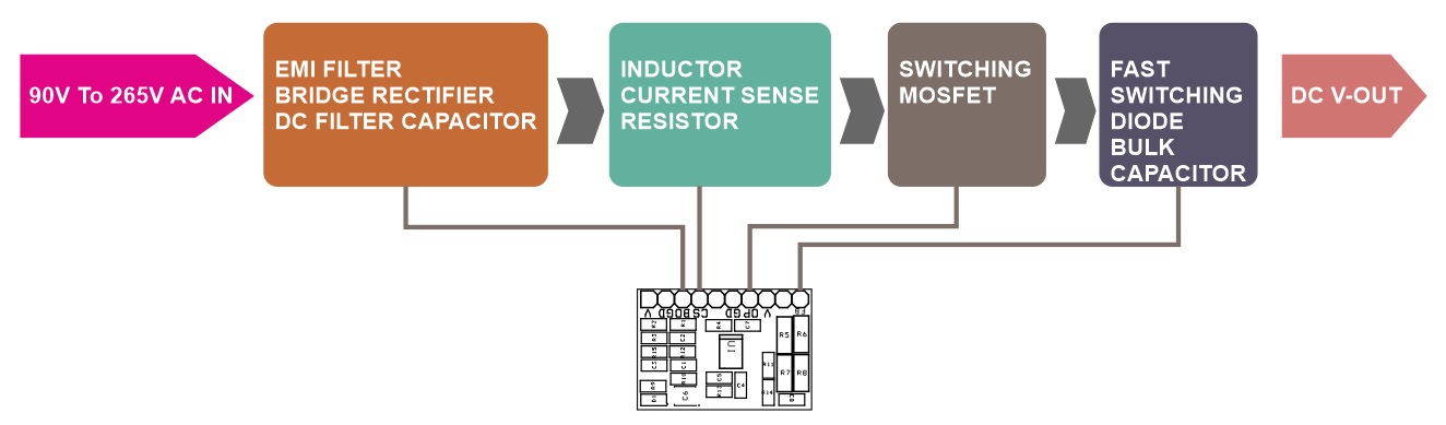
Block Diagram
Application Schematic
Functional Block Diagram
Gerber View
Photos