H-Bridge for LLC and Phase-Shifted DC-DC Converters
LLC/Phase-Shift DC-DC Development Board : NXV65HR82DZ2 H-Bridge, 2x L6491 drivers, OC shutdown, and current sensing.
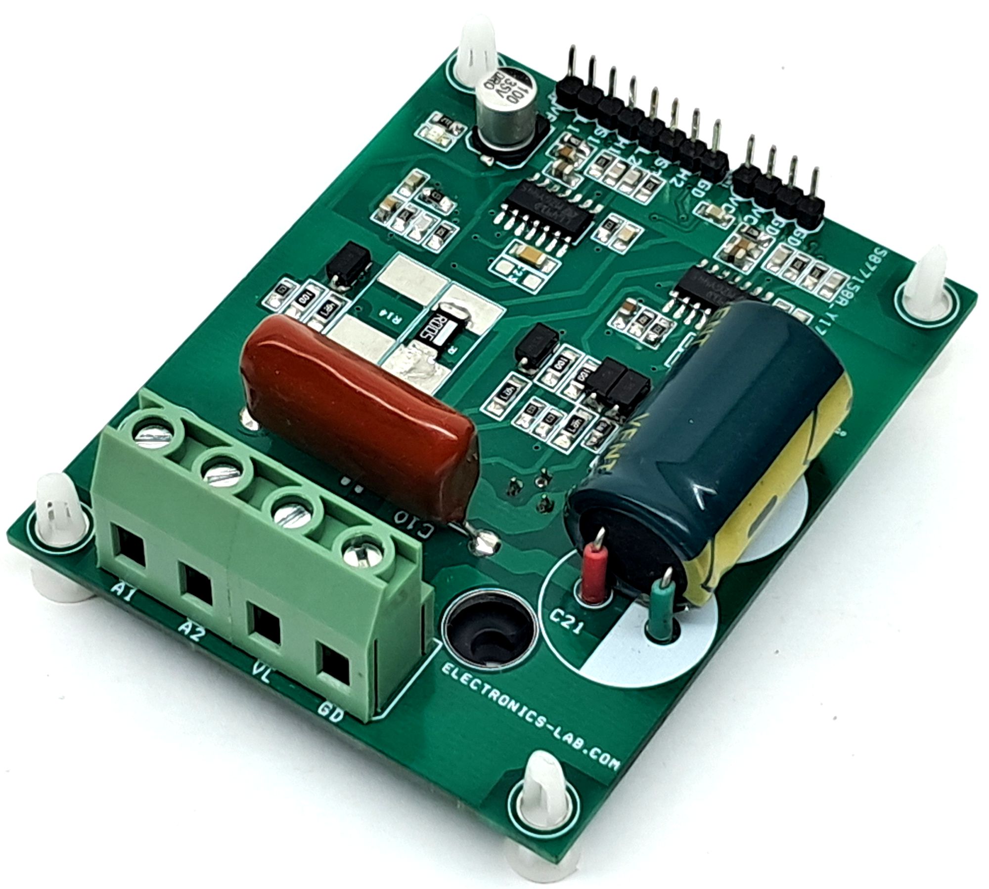
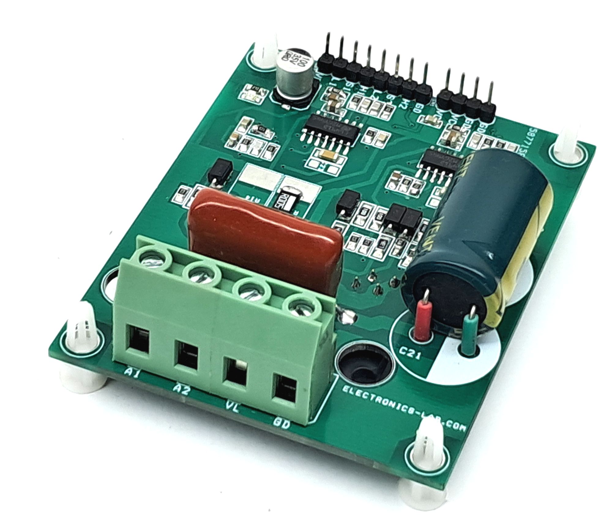
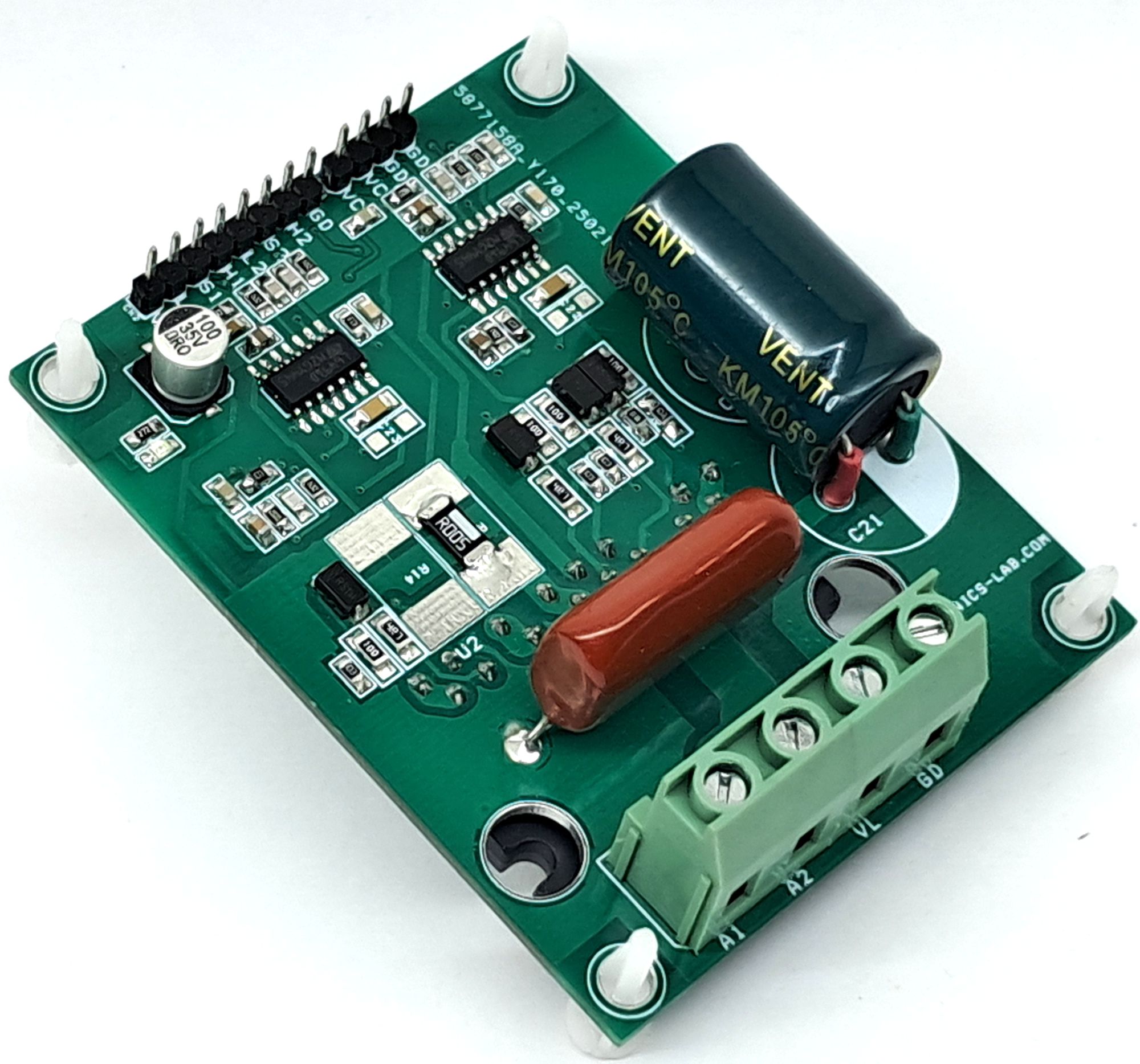
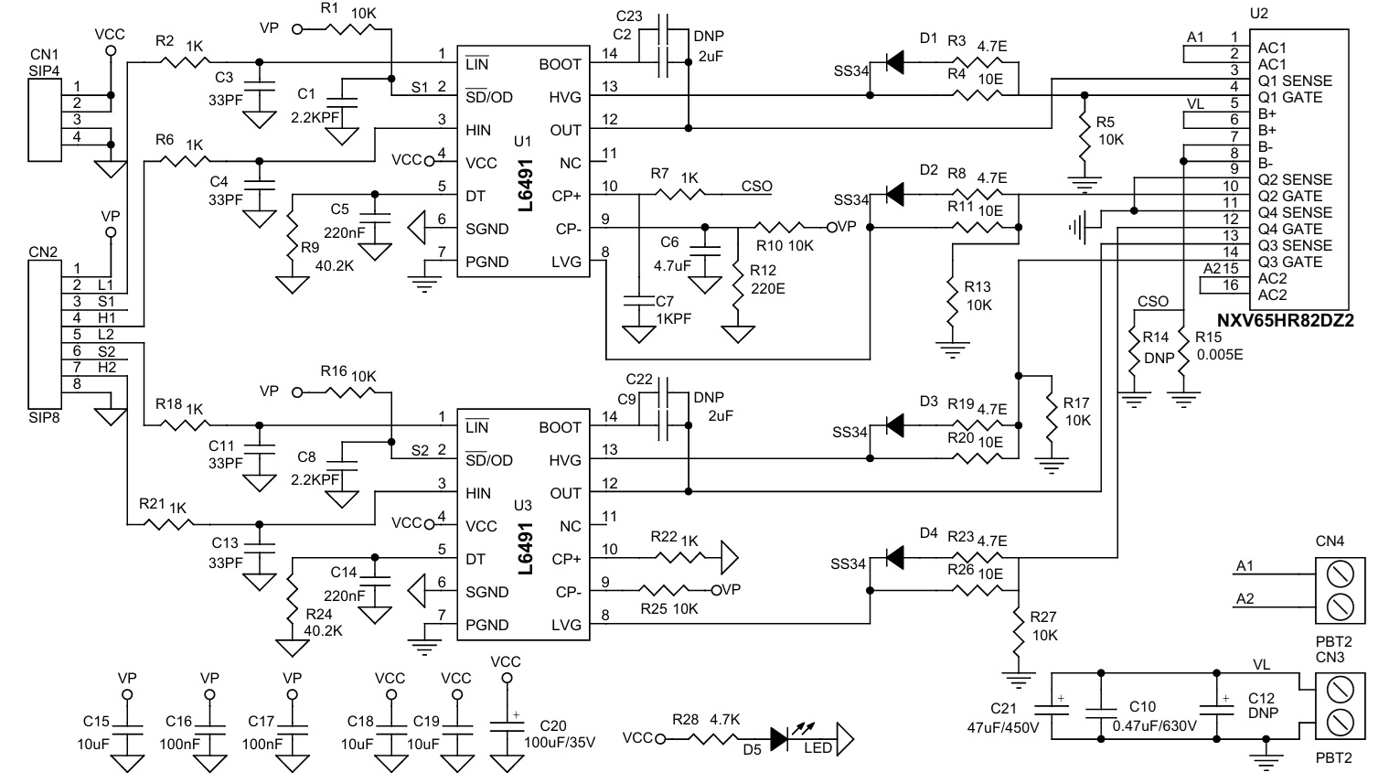
This board is primarily designed for the development of LLC and phase-shifted DC-DC converters. It features the NXV65HR82DZ2 H-Bridge IC along with two L6491 gate driver ICs. The circuit also includes a current sensing function, leveraging the built-in current sense shutdown feature of the L6491. In the event of an overcurrent condition, the device provides a low signal at the S1 pin. LED D5 serves as the power indicator.
Features
- Gate driver power supply: 15 V DC (10 V to 20 V range)
- Load supply: up to 400 V DC
- Gate driver input: 3.3 V / 5 V TTL/CMOS compatible with hysteresis
- Overcurrent output
- Enable input
- On-board Gate power LED
- 4 × 4 mm PCB mounting holes
- PCB dimensions: 77.63 mm × 62.23 mm
Benefits
- Enables the design of small, efficient, and reliable systems
- Helps reduce vehicle fuel consumption and CO₂ emissions
- Simplified assembly with an optimized PCB layout
- High level of integration
- Improved thermal performance
Design Flexibility and Configuration
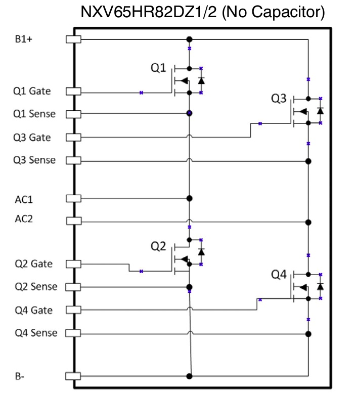
Two versions of the NXV65HR82 chip are available:
- One with an integrated DC bus capacitor
- One without the capacitor
Users can select the appropriate version based on application requirements.
This is an open-design board that allows customization:
- Shunt resistor value can be selected based on the desired overcurrent threshold
- Gate resistors can be chosen according to switching frequency and PWM characteristics
- Resistors R9 and R24 are provided to configure the gate driver dead time
The gate driver operates with a 15 V DC supply (operating range: 10 V to 20 V DC).
Current Sense
The L6491 integrates a comparator dedicated to fault sensing. The comparator input is connected to an external shunt resistor (R15) to implement overcurrent detection.
The comparator output drives an internal open-drain MOSFET, with pull-up resistors R1 and R16 shared with the shutdown (SD) input. When an overcurrent condition is detected, the device enters shutdown mode, and both outputs are forced low, placing the half-bridge in a high-impedance (three-state) condition.
The PCB provides options to mount two shunt resistors (R14 and R15) in SMD 4725 package size. By default, the board is populated with a 0.005 Ω resistor in 2512 package size. Users can select an appropriate resistor value based on the required overcurrent threshold.
Default Current sense threshold is 0.108V, can be alter as per requirement (Resistor divider R10, R12), Resistor R15 shunt resistor value 0.005Ohm provide 100mV (0.1V) at 20Amp current.
In common overcurrent protection architectures, the comparator output is usually connected to an RC network is connected to this SD input and SD/OD line in order to provide a monostable circuit, which implements a protection time following the fault condition. Differently from the common fault detection systems, the L6491 smart shutdown architecture allows immediate turn-off of the output gate driver in case of fault, by minimizing the propagation delay between the fault detection event and the current output switch-off. In fact, the time delay between the fault and the output turn-off is no longer dependent on the RC value of the external network connected to the SD/OD pin. In the smart shutdown circuitry, the fault signal has a preferential path which directly switches off the outputs after the comparator triggering. At the same time, the internal logic turns on the open-drain output and holds it on until the SD voltage goes below the smart SD unlatch threshold VSSD. When such threshold is reached, the open-drain output is turned off, allowing the external pull-up to recharge the capacitor. The driver outputs restart following the input pins as soon as the voltage at the SD/OD pin reaches the higher threshold of the SD logic input. The smart shutdown system gives the possibility to increase the time constant of the external RC network (that determines the disable time after the fault event) up to very large values without increasing the delay time of the protection. Any external signal provided to the SD pin is not latched and can be used as control signal in order to perform, for instance, PWM chopping through this pin. In fact, when a PWM signal is applied to the SD input and the logic inputs of the gate driver are stable, the outputs switch from the low level to the state defined by the logic inputs and vice versa.
DC Bus Capacitor
- A 47 µF / 450 V capacitor (C21) is installed by default. An additional capacitor (C12) can be populated if a higher DC bus capacitance is required for the application.
- Electrolytic Capacitor – 16 mm Diammeter
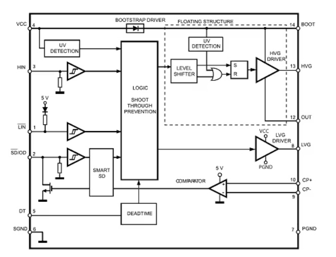
L6491 Description
It is a single-chip half-bridge gate driver for N-channel power MOSFETs or IGBTs, with a 4 A sink and source current capability. The high-side (floating) section is designed to stand a voltage rail up to 600 V. The logic inputs are CMOS/TTL compatible down to 3.3 V for easy interfacing a microcontroller or DSP. An integrated comparator is available for fast overcurrent protection, and is also suited for other functions such overtemperature, etc. An integrated comparator is available for fast protection against over-current, over-temperature, etc.
L6491 Features
- Power Supply 15V (Range 10V to 20V)
- dV/dt immunity ± 50 V/ns in full temperature range
- Driver current capability: 4 A source/sink
- Switching times 15 ns rise/fall with 1 nF load
- 3 V, 5 V TTL/CMOS inputs with hysteresis
- Integrated bootstrap diode
- Smart shutdown function
- Adjustable deadtime (Resistor R9 and R24)
- Interlocking function
- Effective fault protection
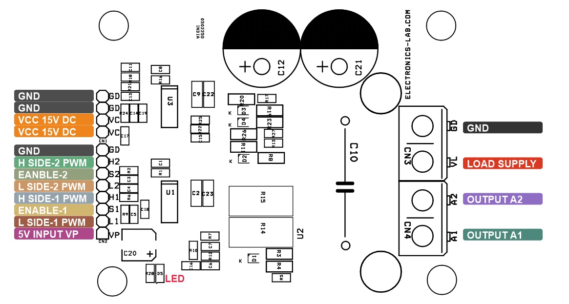
Connections
- CN1: Pin 1,2 = VCC Logic Gate Supply 15V DC, Pin 3,4= GND
- CN2: Pin 1 = VP-5V DC, Current Shut Down Threshold Power Input, Pin 2 = PWM Input Low Side 1. Pin 3 = Shutdown1/Fault1, Pin 4= PWM Input High Side 1, Pin 5 = PWM Low Side Input 2, Pin 6 = Shutdown2/Fault2, Pin 7 = PWM Input High Side 2, Pin 8 = GND
- CN3: Pin 1 = Load Power Up to 400V DC, Pin 2 = Power GND
- CN4: Pin 1 = Load A, Pin 2 = Load 2
- D5: Power LED
Schematic
Parts List
| NO. | QNTY. | REF. | DESC. | MANUFACTURER | SUPPLIER | SUPPLIER PART NO |
|---|---|---|---|---|---|---|
| 1 | 1 | CN1 | 4 PIN MALE HEADER PITCH 2.54MM | WURTH | DIGIKEY | 732-5317-ND |
| 2 | 1 | CN2 | 8 PIN MALE HEADER PITCH 2.54MM | WURTH | DIGIKEY | 732-5321-ND |
| 3 | 2 | CN3,CN4 | 2 PIN SCREW TERMINAL PITCH 7.62MM | WURTH | DIGIKEY | 732-691254410002-ND |
| 4 | 2 | C1,C8 | 2.2KPF/50V CERAMIC SMD SIZE 0805 | YAGEO/MURATA | DIGIKEY | |
| 5 | 2 | C2,C9 | 2uF/25V CERAMIC SMD SIZE 1206 | YAGEO/MURATA | DIGIKEY | |
| 6 | 4 | C3,C4,C11,C13 | 33PF/50V CERAMIC SMD SIZE 0805 | YAGEO/MURATA | DIGIKEY | |
| 7 | 2 | C5,C14 | 220nF/50V CERAMIC SMD SIZE 0805 | YAGEO/MURATA | DIGIKEY | |
| 8 | 1 | C6 | 4.7uF/50V CERAMIC SMD SIZE 0805 | YAGEO/MURATA | DIGIKEY | |
| 9 | 1 | C7 | 1KPF/50V CERAMIC SMD SIZE 0805 | YAGEO/MURATA | DIGIKEY | |
| 10 | 1 | C10 | 0.47uF/630V | PANASONIC | DIGIKEY | P14532-ND |
| 11 | 2 | C12,R14 | DNP | |||
| 12 | 3 | C15,C18,C19 | 10uF/50V CERAMIC SMD SIZE 0805 | YAGEO/MURATA | DIGIKEY | |
| 13 | 2 | C16,C17 | 100nF/50V CERAMIC SMD SIZE 0805 | YAGEO/MURATA | DIGIKEY | |
| 14 | 1 | C20 | 100uF/35V ELECTROLYTIC | WURTH | DIGIKEY | 732-8511-1-ND |
| 15 | 1 | C21 | 47uF/450V ELECTROLYTIC | PANASONIC | DIGIKEY | P13678-ND |
| 16 | 2 | C22,C23 | DNP | |||
| 17 | 4 | D1,D2,D3,D4 | SS34 | ON SEMI | DIGIKEY | SS34FSCT-ND |
| 18 | 1 | D5 | LED RED SMD SIZE 0805 | OSRAM | DIGIKEY | 475-1278-1-ND |
| 19 | 8 | R1,R5,R10,R13,R16,R17,R25,R27 | 10K 5% SMD SIZE 0805 | YAGEO/MURATA | DIGIKEY | |
| 20 | 6 | R2,R6,R7,R18,R21,R22 | 1K 5% SMD SIZE 0805 | YAGEO/MURATA | DIGIKEY | |
| 21 | 4 | R3,R8,R19,R23 | 4.7E 5% SMD SIZE 1206 | YAGEO/MURATA | DIGIKEY | |
| 22 | 4 | R4,R11,R20,R26 | 10E 5% SMD SIZE 1206 | YAGEO/MURATA | DIGIKEY | |
| 23 | 2 | R9,R24 | 40.2K 1% SMD SIZE 0805 | YAGEO/MURATA | DIGIKEY | |
| 24 | 1 | R12 | 220E 1% SMD SIZE 0805 | YAGEO/MURATA | DIGIKEY | |
| 25 | 1 | R15 | 0.005E/3W SMD SIZE 2512 | BOURNS INC | DIGIKEY | CRE2512-FZ-R005E-3CT-ND |
| 26 | 1 | R28 | 4.7K 5% SMD SIZE 0805 | YAGEO/MURATA | DIGIKEY | |
| 27 | 2 | U1,U3 | L6491 | ST | DIGIKEY | 497-15443-5-ND |
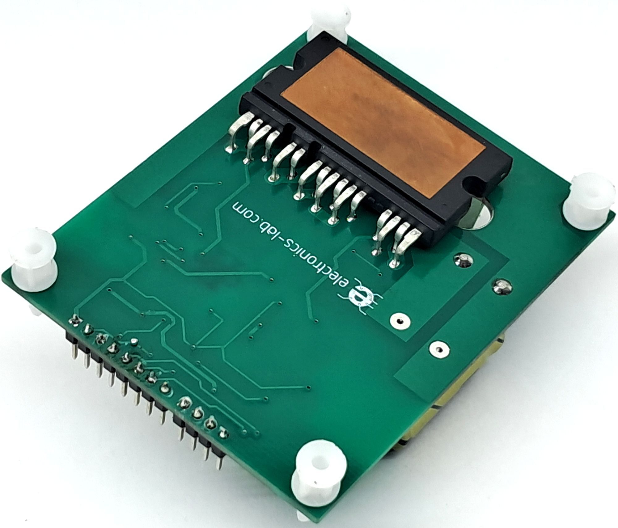
| 28 | 1 | U2 | NXV65HR82DZ2 | ON SEMI | DIGIKEY | 488-NXV65HR82DZ2-ND |
Connections
Gate Driver Internal Block Diagram
H-Bridge Internal Block Diagram
Gerber View
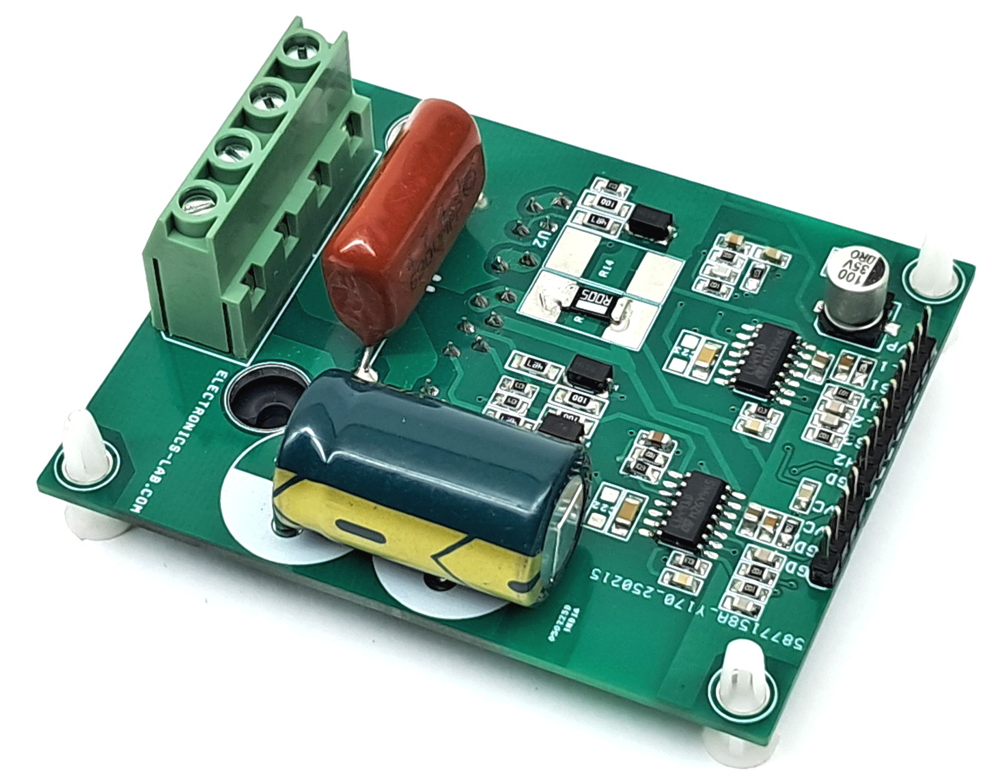
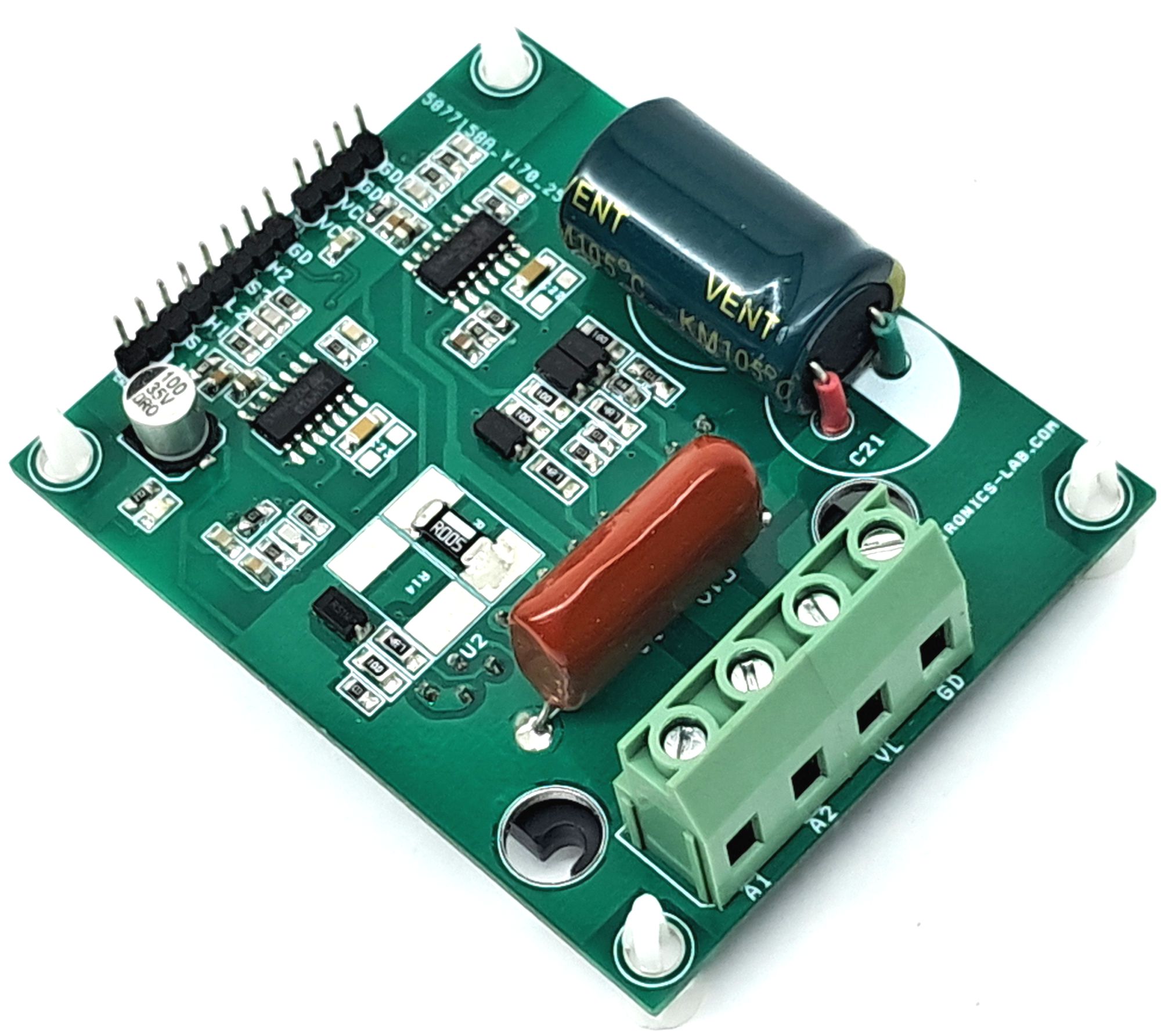
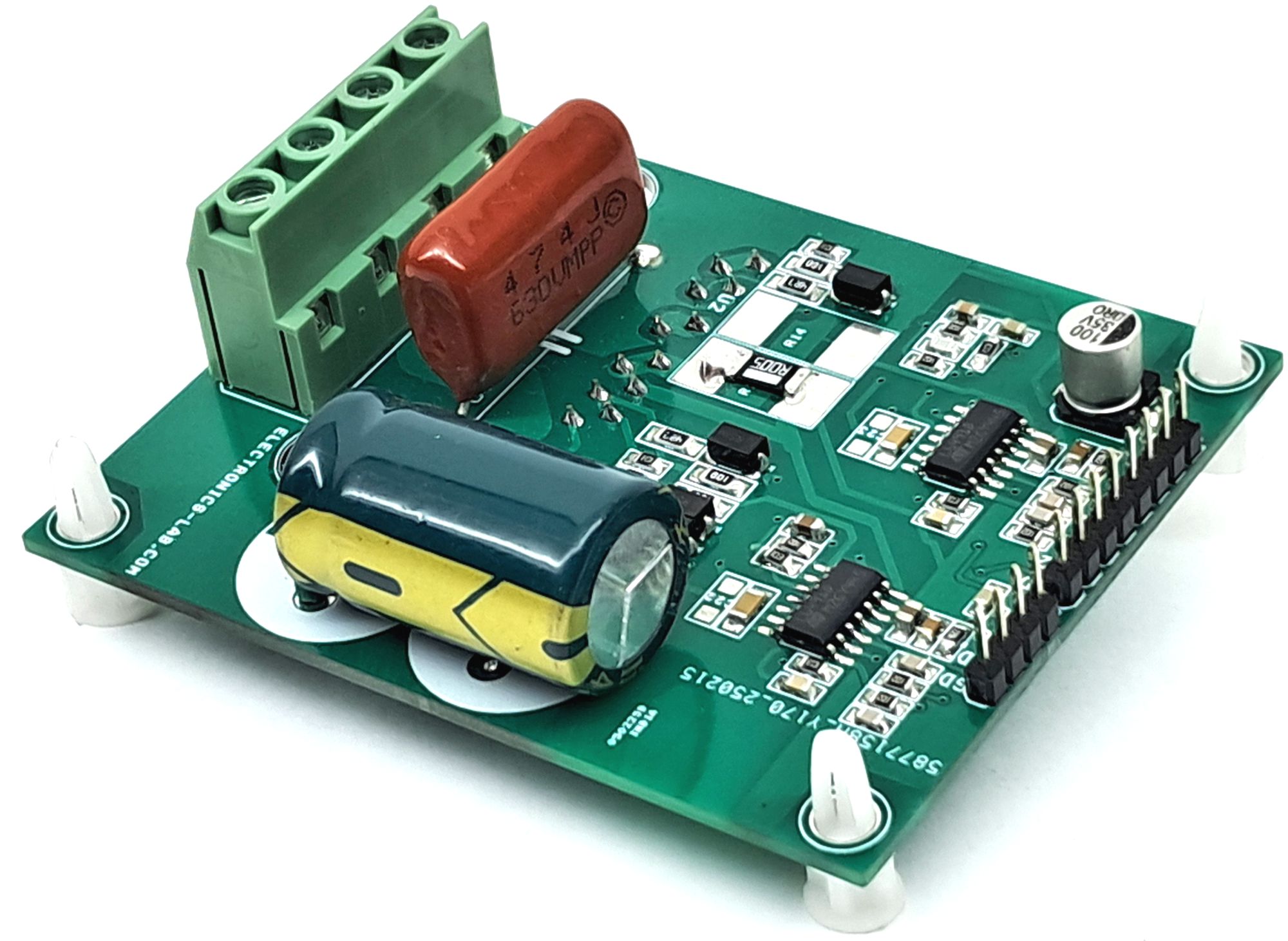
Photos