High-Current Half-Bridge for Automotive Applications
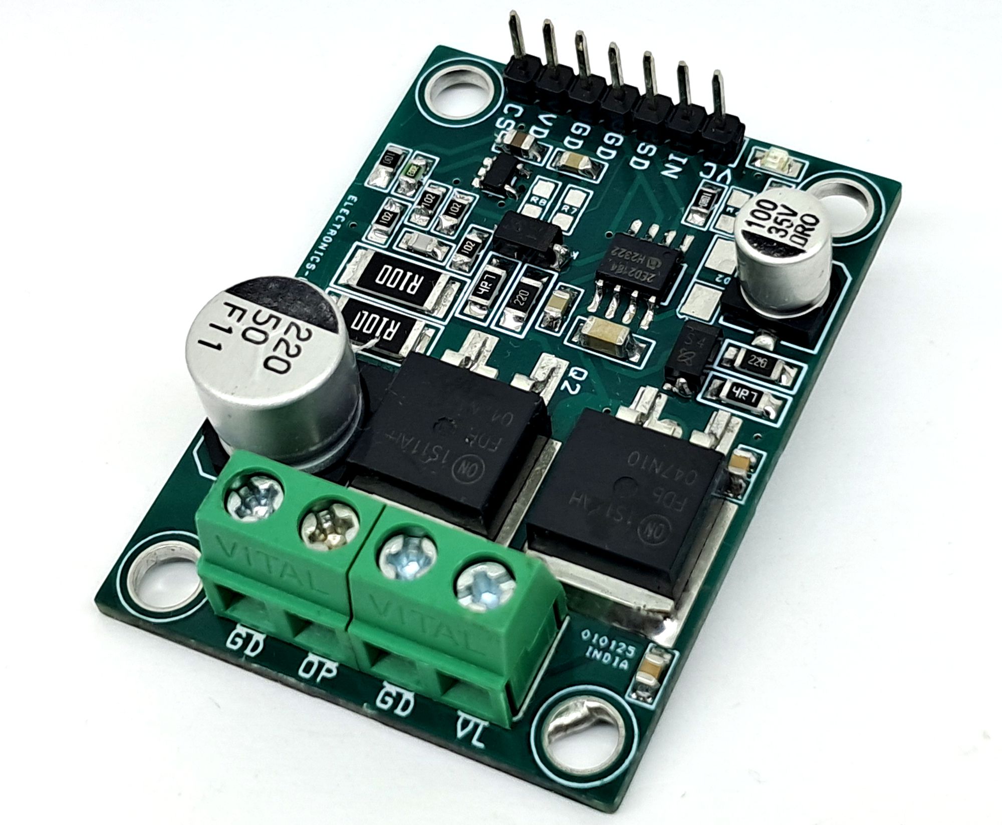
This compact, high-current half-bridge driver utilizes a 2ED2184S06F gate driver and dual FDB047N10 MOSFETs to support various power applications, offering up to 10A of continuous current and flexible control interfaces for tasks like motor control and solar systems.
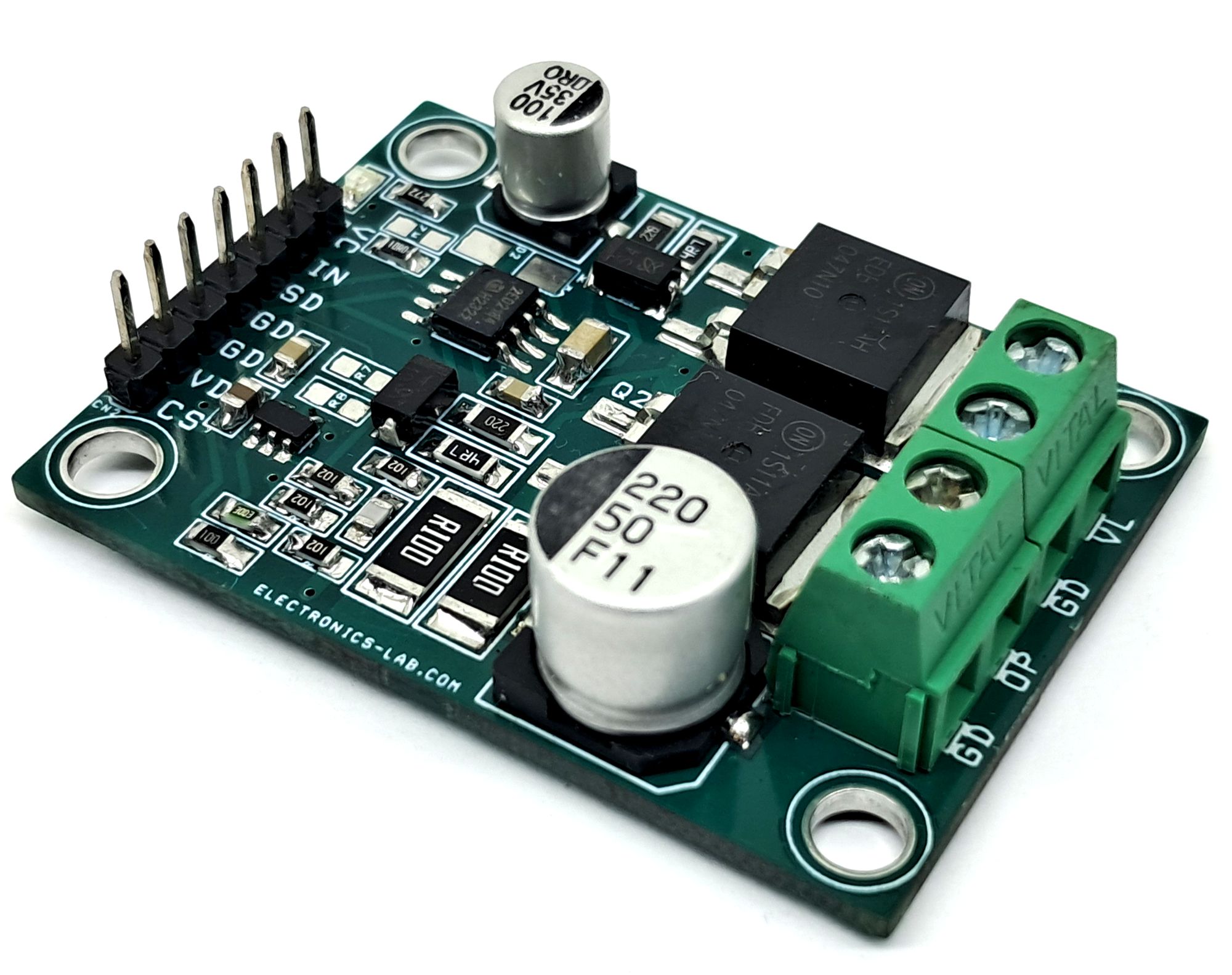
This low-voltage, high-current half-bridge driver is designed for solar systems, motor control, DC-DC converters, chargers and many other power applications.
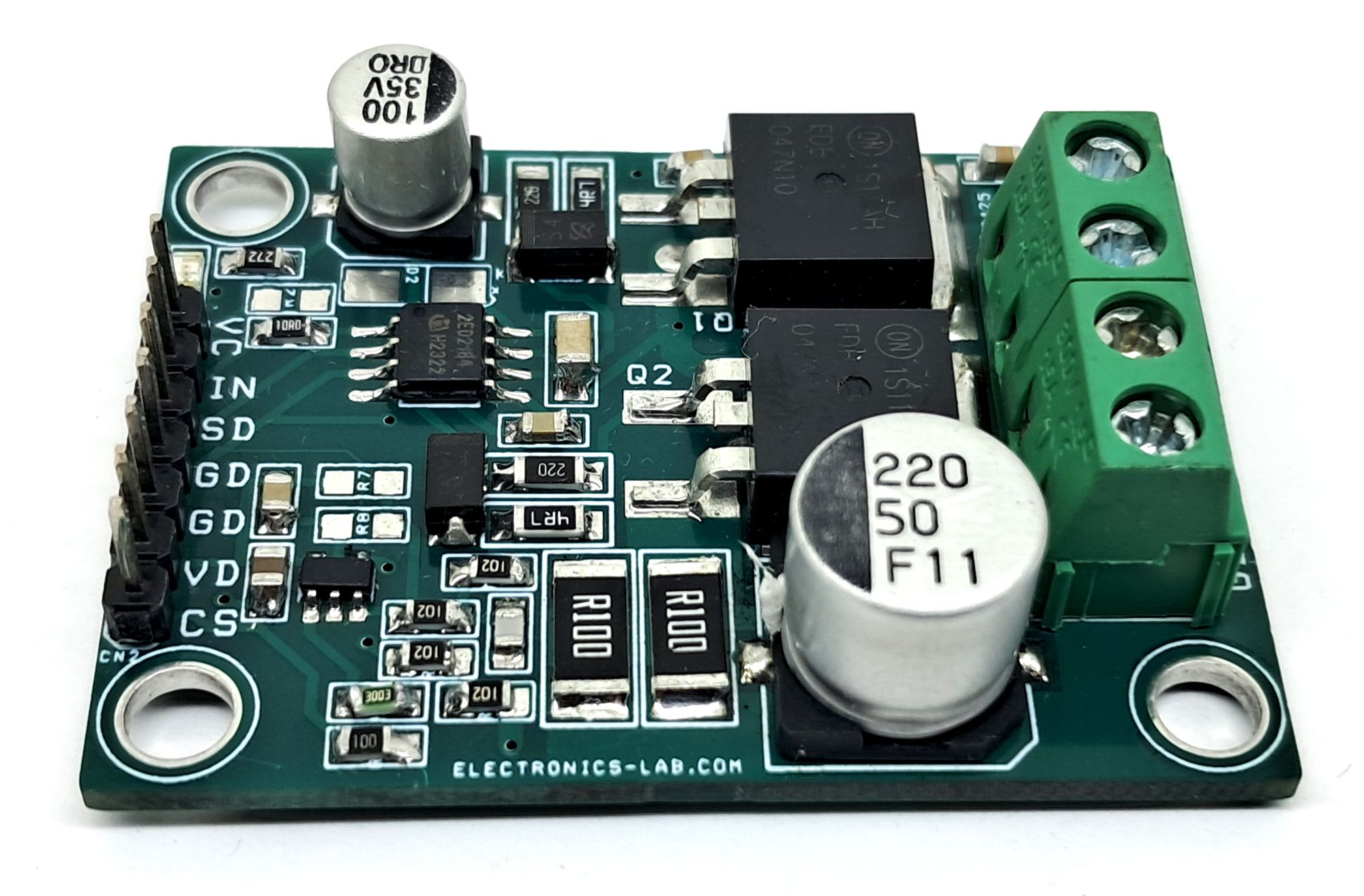
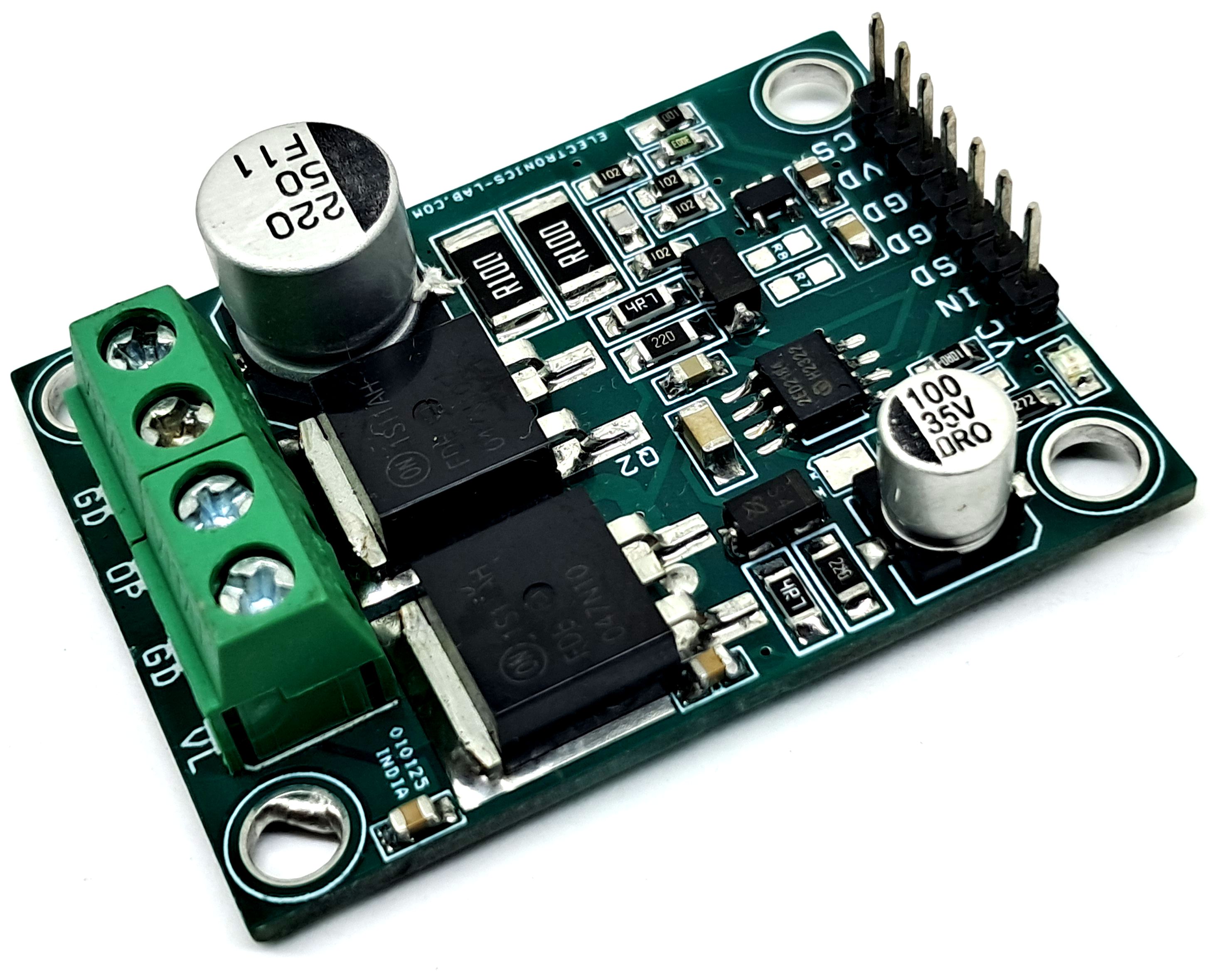
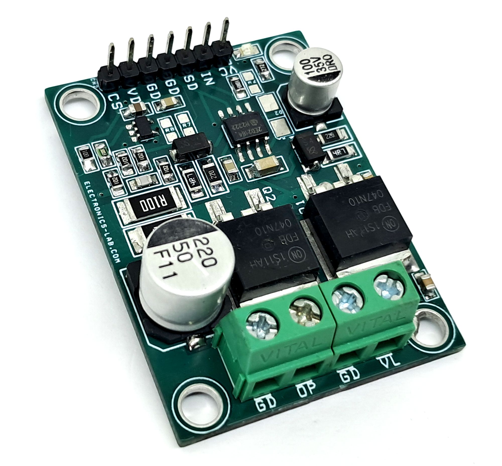
The board is built around the 2ED2184S06F gate driver IC and uses two FDB047N10 MOSFETs, along with an optional current-sense circuit.
Screw terminals are provided for load power and load connections, while header connectors are available for gate driver power, control inputs, and optional current-sense output.
An onboard optional regulator provides 5V DC for the current-sense circuit.
This compact board can drive continuous current up to 10A. However, proper cooling is strongly recommended when operating at high load currents. The board has been tested up to 5A load, at 20kHz switching frequency, with a duty cycle range of 5% to 95%, using a 48V DC supply.
The gate driver requires a 12–15V DC supply. An onboard LED indicates the presence of logic power.
Features
- Load power supply: 12V to 48V DC
- Gate Driver Logic Power Supply 12V to 15V DC
- Load current: Up to 5A (Tested)
- Onboard logic power LED indicator
- Frequency Tasted Up to 40Khz
- Duty cycle range: 5% to 95%
- Screw terminals for load and power connections
- Header connectors for logic power and signal I/O
- Optional onboard current-sense circuit
- PCB dimensions: 49.05 × 36.04 mm
- 4 x 4 mm PCB mounting holes
Power Supply
Maximum recommended load supply: up to 48V DC
MOSFET Compatibility
Users may select alternative MOSFETs or IGBTs depending on application requirements.
The gate driver supports both MOSFETs and IGBTs, allowing flexibility based on load current, operating voltage, and switching frequency.
Typical Applications
- High-current battery chargers
- Motor drivers
- Solenoid and contactor drivers
- Resistive loads and heaters
The 2ED2184(4)S06F(J) is a half-bridge high voltage, high speed power MOSFET and IGBT driver with independent high and low side referenced output channels. Based on Infineon’s SOI-technology there is an excellent ruggedness and noise immunity with capability to maintain operational logic at negative voltages of up to – 11 VDC on VS pin (VCC = 15 V) on transient voltages. There are not any parasitic thyristor structures present
in the device, hence no parasitic latch up may occur at all temperature and voltage conditions. The logic input is compatible with standard CMOS or LSTTL output, down to 3.3 V logic. The output drivers feature a high pulse current buffer stage designed for minimum driver cross-conduction. The floating channel can be used to drive an N-channel power MOSFET, SiC MOSFET or IGBT in the high side configuration, which operate up to 650 V.
Current Sense Circuit – Op-Amp Based
An optional current sense circuit is provided with dual configuration options. In the op-amp–based configuration, the circuit generates an output voltage proportional to the load current.
Users can select appropriate resistor and capacitor values according to the required current measurement range and gain. All resistors and capacitors are SMD 0805 package size, while the current sense resistor is SMD 2512 package size to handle higher power dissipation.
Current Sense Circuit – Comparator Based (Overcurrent Protection)
An overcurrent fault output circuit can be implemented using a comparator configuration. In this setup, one input of the comparator is connected to the current sense signal, while the other input is connected to a reference voltage generated using a resistor divider network.
When the sensed current exceeds the preset threshold, the comparator output triggers a fault signal, enabling overcurrent protection functionality.
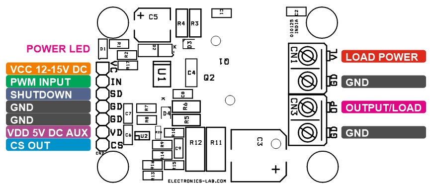
Connections
- CN1: Pin 1 = +Load Power 12V to 48V DC, Pin 2 = GND
- CN2: Pin 1 = VCC Gate Driver 12V-15V DC, Pin 2 = PWM Input, Pin 3 = Shutdown, Pin 4 = GND, Pin 5 = GND, Pin 6 = VDD 5V DC AUX, Pin 7 = Optional Current Sense
- CN3: Pin 1 = GND, Pin 2 = Load/Output
- D1: Logic Power LED
Arduino Code
Arduino test code is provided to verify the functionality of the board. Connect CN2 Pin 2 to Arduino digital pin D9.
The shutdown (SD) pin may be left floating or driven TTL-High for normal operation. Driving this pin LOW will disable the driver.
This example code generates a 20 kHz PWM signal on pin D9 with the following sequence:
- 5% duty cycle for 3 seconds
- 95% duty cycle for 3 seconds
The sequence repeats continuously in a loop.
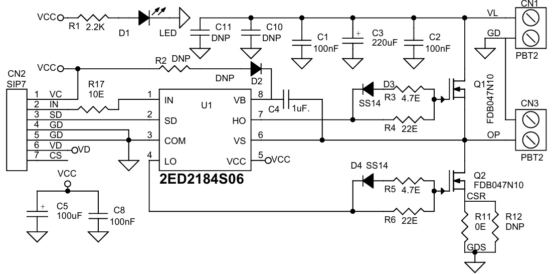
Schematic
Parts List
| No. | QNTY. | REF. | DESC. | MANUFACTURER | SUPPLIER | SUPPLIER PART NO |
|---|---|---|---|---|---|---|
| 1 | 2 | CN1,CN3 | 2 PIN SCREW TERMINAL PITCH 5.08MM | PHOENIX | DIGIKEY | 277-1247-ND |
| 2 | 1 | CN2 | 7 PIN MALE HEADER PITCH 2.54MM | WURTH | DIGIKEY | 732-5320-ND |
| 3 | 3 | C1,C2,C8 | 100nF/50V CERAMIC SMD SIZE 0805 | YAGEO/MURATA | DIGIKEY | |
| 4 | 1 | C5 | 100uF/25V DC | DIGIKEY | ||
| 5 | 1 | C3 | 220uF/50V | DIGIKEY | ||
| 6 | 1 | C4 | 1uF25V CERAMIC SMD SIZE 1206 | YAGEO/MURATA | DIGIKEY | |
| 7 | 2 | C10,C11 | DNP | DIGIKEY | ||
| 8 | 1 | D1 | LED RED SMD SIZE 0805 | OSRAM | DIGIKEY | 475-1278-1-ND |
| 9 | 3 | D2,D3,D4 | SS14 | ONSEMI | DIGIKEY | SS14CT-ND |
| 10 | 2 | Q1,Q2 | FDB047N10 | ONSEMI | DIGIKEY | FDB047N10CT-ND |
| 11 | 1 | R1 | 2.2K 5% SMD SIZE 0805 | YAGEO/MURATA | DIGIKEY | |
| 12 | 1 | R17 | 10E 5% SMD SIZE 0805 | YAGEO/MURATA | DIGIKEY | |
| 13 | 2 | R3,R5 | 4.7E 5% SMD SIZE 1206 | YAGEO/MURATA | DIGIKEY | |
| 14 | 2 | R4,R6 | 22E 5% SMD SIZE 1206 | YAGEO/MURATA | DIGIKEY | |
| 15 | 1 | R11 | 0E 5% SMD SIZE 0805 | YAGEO/MURATA | DIGIKEY | |
| 16 | 1 | U1 | 2ED2184S06 | INFINION | DIGIKEY | 2ED2184S06FXUMA1 |
| 17 | 2 | R12,R2 | DNP | |||
| 18 | 1 | R13 | DNP-10E | OPTIONAL | DO NOT POPULATE | |
| 19 | 1 | R15 | DNP-1K. | OPTIONAL | DO NOT POPULATE | |
| 20 | 1 | R16 | DNP-20K | OPTIONAL | DO NOT POPULATE | |
| 21 | 1 | R18 | DNP-4.7E. | OPTIONAL | DO NOT POPULATE | |
| 22 | 1 | R19 | DNP-4.7E, | OPTIONAL | DO NOT POPULATE | |
| 23 | 1 | U2 | DNP-SGM721/MCP6021 | OPTIONAL | DO NOT POPULATE | |
| 24 | 1 | U3 | DNP-L1117-5V. | OPTIONAL | DO NOT POPULATE | |
| 25 | 1 | C6 | DNP-10uF | OPTIONAL | DO NOT POPULATE | |
| 26 | 1 | C7 | DNP-100nF | OPTIONAL | DO NOT POPULATE | |
| 27 | 1 | C9 | DNP-100PF. | OPTIONAL | DO NOT POPULATE | |
| 28 | 1 | R13 | DNP-10E | OPTIONAL | DO NOT POPULATE | |
| 29 | 1 | R15 | DNP-1K. | OPTIONAL | DO NOT POPULATE | |
| 30 | 1 | R16 | DNP-20K | OPTIONAL | DO NOT POPULATE | |
| 31 | 1 | R18 | DNP-4.7E. | OPTIONAL | DO NOT POPULATE | |
| 32 | 1 | R19 | DNP-4.7E, | OPTIONAL | DO NOT POPULATE | |
| 33 | 3 | R7,R8,R20 | DNP-C | OPTIONAL | DO NOT POPULATE | |
| 34 | 3 | R9,R10,R14 | DNP-1K | OPTIONAL | DO NOT POPULATE |
Connections
Gerber View
Photos