I2C Programmable PWMs to Control a DC Motor and LED
This project features an I²C-controlled DS1050 PWM generator paired with a 17A MOSFET to drive LEDs and resistive loads, with the flexibility to handle high-current or inductive loads provided proper heat management and flyback protection are utilized.
This project is based on the DS1050 chip, a 5-bit pulse-width modulator (PWM) controlled via a 2-wire (I²C) interface. The 2-wire bus allows a single master device to control up to eight slave devices (DS1050 or other compatible 2-wire peripherals). The project consists of a DS1050 I²C PWM generator combined with a MOSFET stage capable of driving high-current loads. It is primarily designed for driving LEDs and resistive loads, but it can also be used with inductive loads when an external flyback diode is added to protect against back-EMF.
A 17A MOSFET is used on the board. Although the board has been tested up to 1A, it is capable of handling higher current when properly heat-managed.
The DS1050 provides a 5-bit programmable PWM output, allowing the duty cycle to be adjusted “on-the-fly” from 0% to 100% in 3.125% steps. It supports up to eight addressable devices on a single I²C bus.
The chip is available in multiple fixed PWM frequencies: 1 kHz, 5 kHz, 10 kHz, and 25 kHz.
The populated board uses the 10 kHz version, DS1050-010 chip, which generates a 10 kHz PWM signal to control the average power delivered to the LED. A lower duty cycle results in lower average power and dimmer light output, while a higher duty cycle increases both the “on” time and LED intensity. For example, a 0% duty cycle fully turns off the LED, while 50% duty cycle drives it at approximately half power.
Features
- Supply 12V DC
- Load Current Up to 1A
- PWM Frequency 10Khz
- Duty cycle Range 0% to 100%
- PWM Control – I2C Protocol
- Very Stable Output
- Tiny Board
- Header Connector for Loads and Power
- On Board 56V Regulator to power the Microcontroller
- On Board Power LED
- PCB Dimensions 26.67 x 20.96 mm
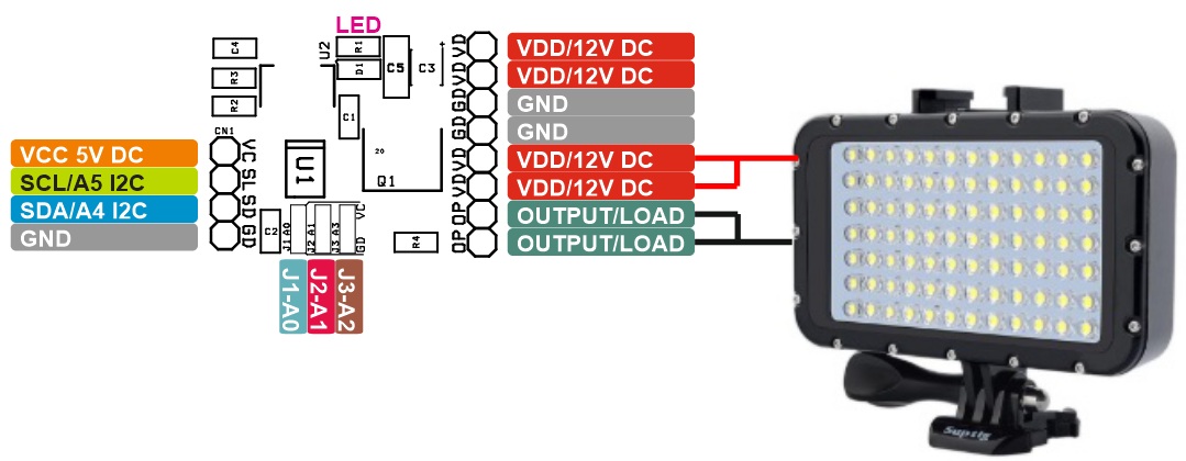
Connections
- CN1: Pin 1 = VCC 5V, Pin 2 = SCL/A5, Pin 3 = SDA/A4, Pin 4 = GND
- CN2: Pin 1,2 = VDD 12V DC, Pin 3,4 = =Load
- CN3: Pin 1,2 = VDD 12V, Pin 2,3 = GND
- D1: Power LED
- Jumper J1 = Address A0, Jumper 2 = Address A1, Jumper 3 = Address = A2
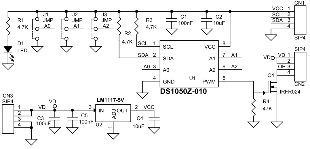
Schematic
Parts List
| NO | QNTY. | REF | DESC. | MANUFACTURER | SUPPLIER | SUPPLIER PART NO |
|---|---|---|---|---|---|---|
| 1 | 3 | CN1,CN2,CN3 | 4 PIN MALE HEADER PITCH 2.54MM | WURTH | DIGIKEY | 732-5317-ND |
| 2 | 2 | C1,C5 | 100nF/16C CERAMIC SMD SIZE 0805 | YAGEO/MURATA | DIGIKEY | |
| 3 | 2 | C2,C4 | 10uF/16V CERAMIC SMD SIZE 0805 | YAGEO/MURATA | DIGIKEY | |
| 4 | 1 | C3 | 100uF/16V CERAMIC SMD SIZE 1201 | YAGEO/MURATA | DIGIKEY | |
| 5 | 1 | D1 | LED RED SMD SIZE 0805 | YAGEO/MURATA | DIGIKEY | |
| 6 | 3 | J1,J2,J3 | JMP/SOLDER JUMPER | |||
| 7 | 1 | Q1 | IRFR024 | VISHAY | DIGIKEY | IRFR024-ND |
| 8 | 3 | R1,R2,R3 | 4.7K 5% SMD SIZE 0805 | YAGEO/MURATA | DIGIKEY | |
| 9 | 1 | R4 | 47K 5% SMD SIZE 0805 | YAGEO/MURATA | DIGIKEY | |
| 10 | 1 | U1 | DS1050Z-010 | ANALOG DEVICE | DIGIKEY | DS1050Z-010+-ND |
| 11 | 1 | U2 | LM1117-5V | TI | DIGIKEY | LM1117IMPX-5.0/NOPBCT-ND |
Connections
Gerber View
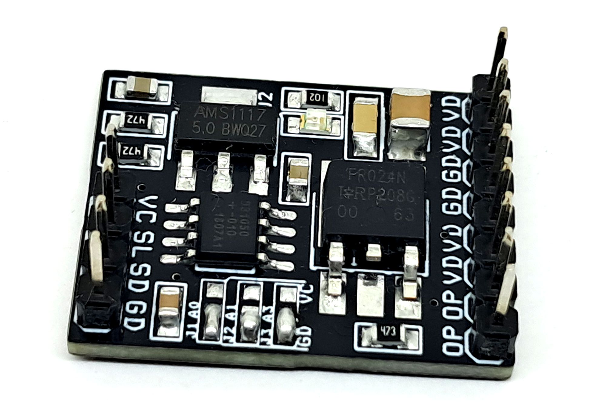
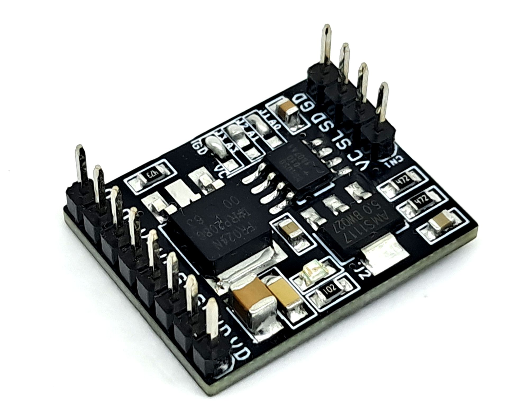
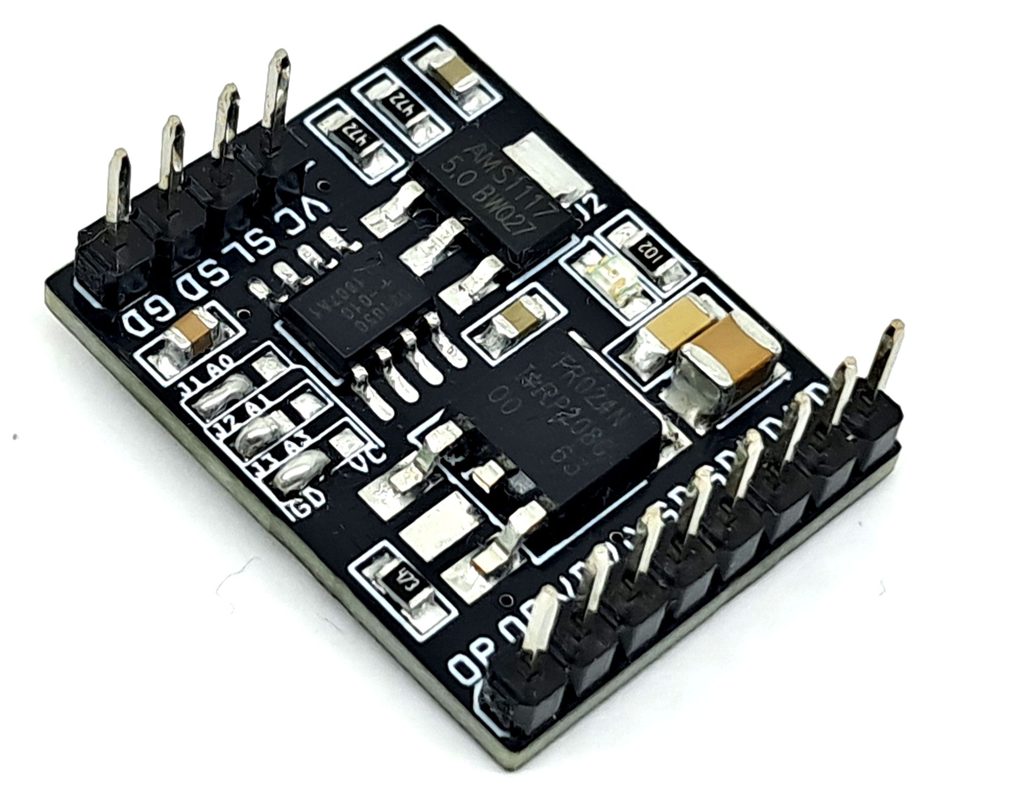
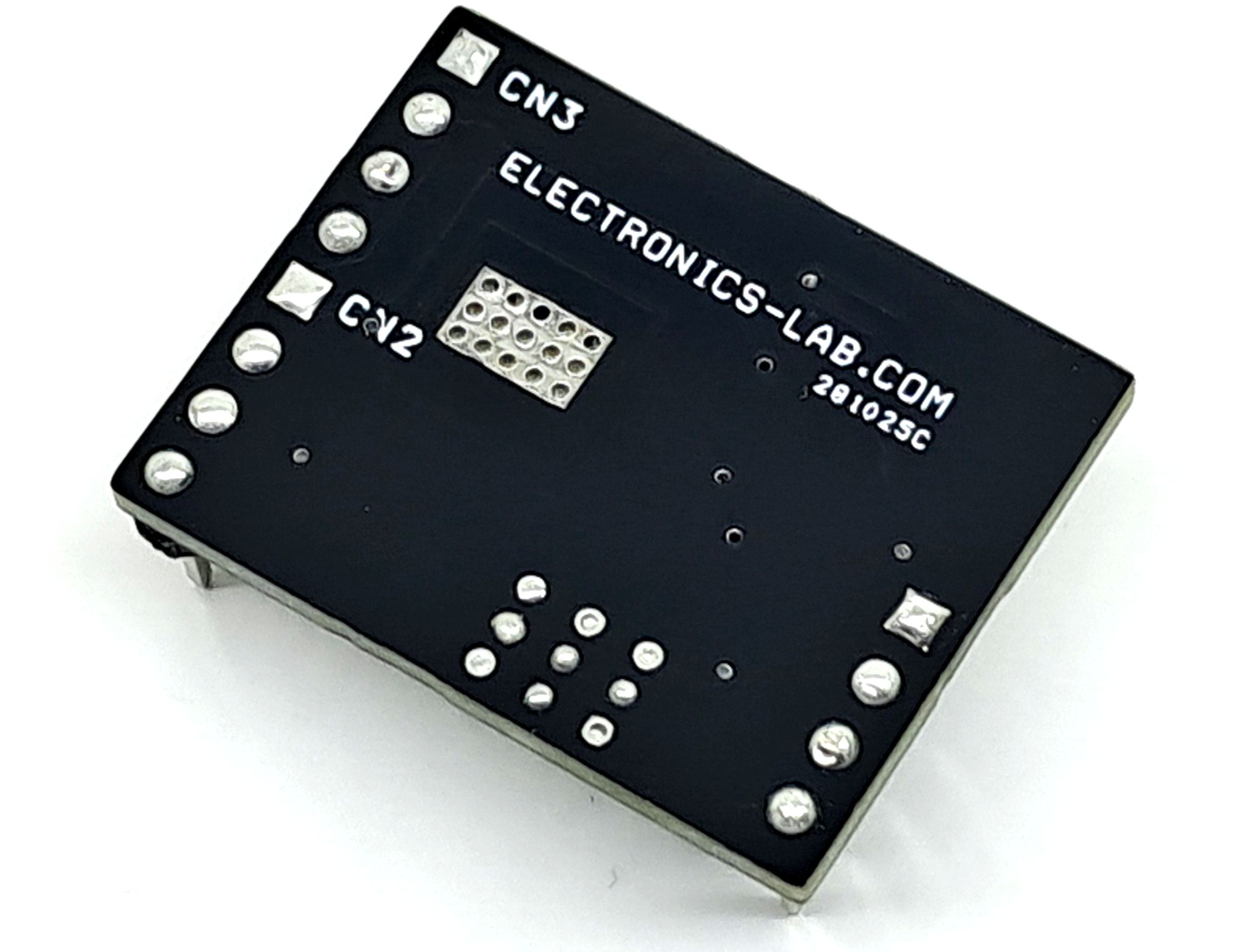
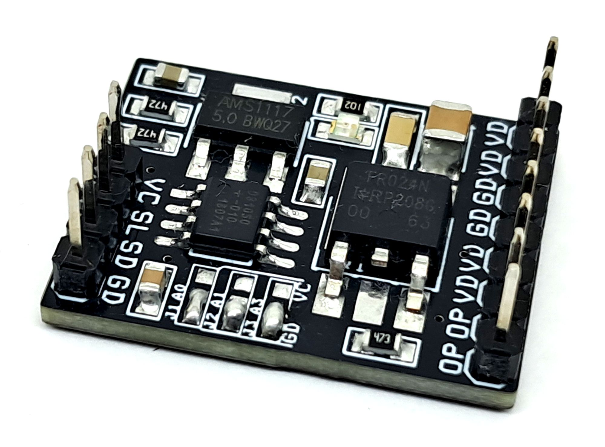
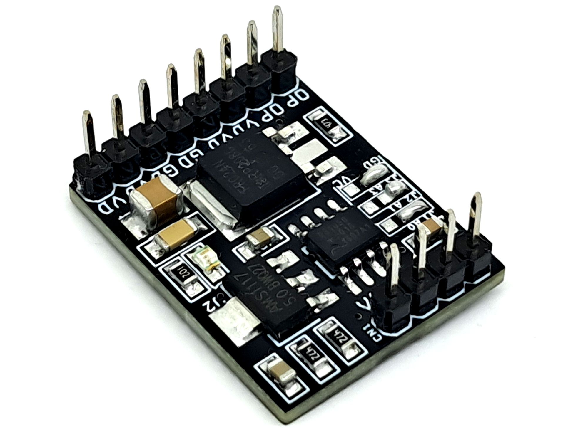
Photos