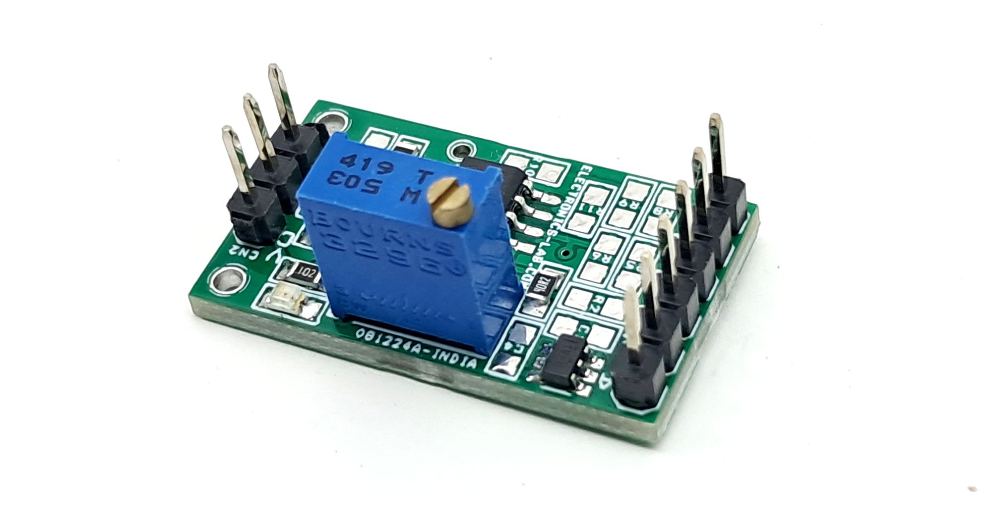
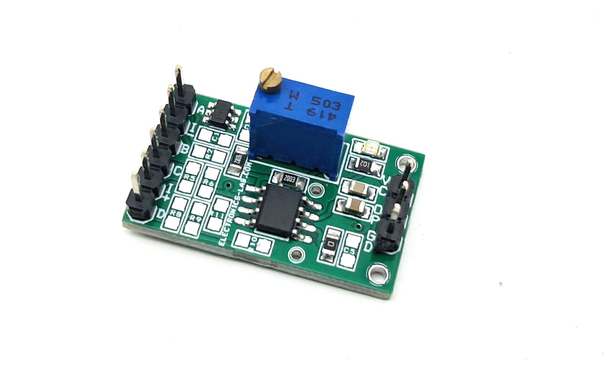
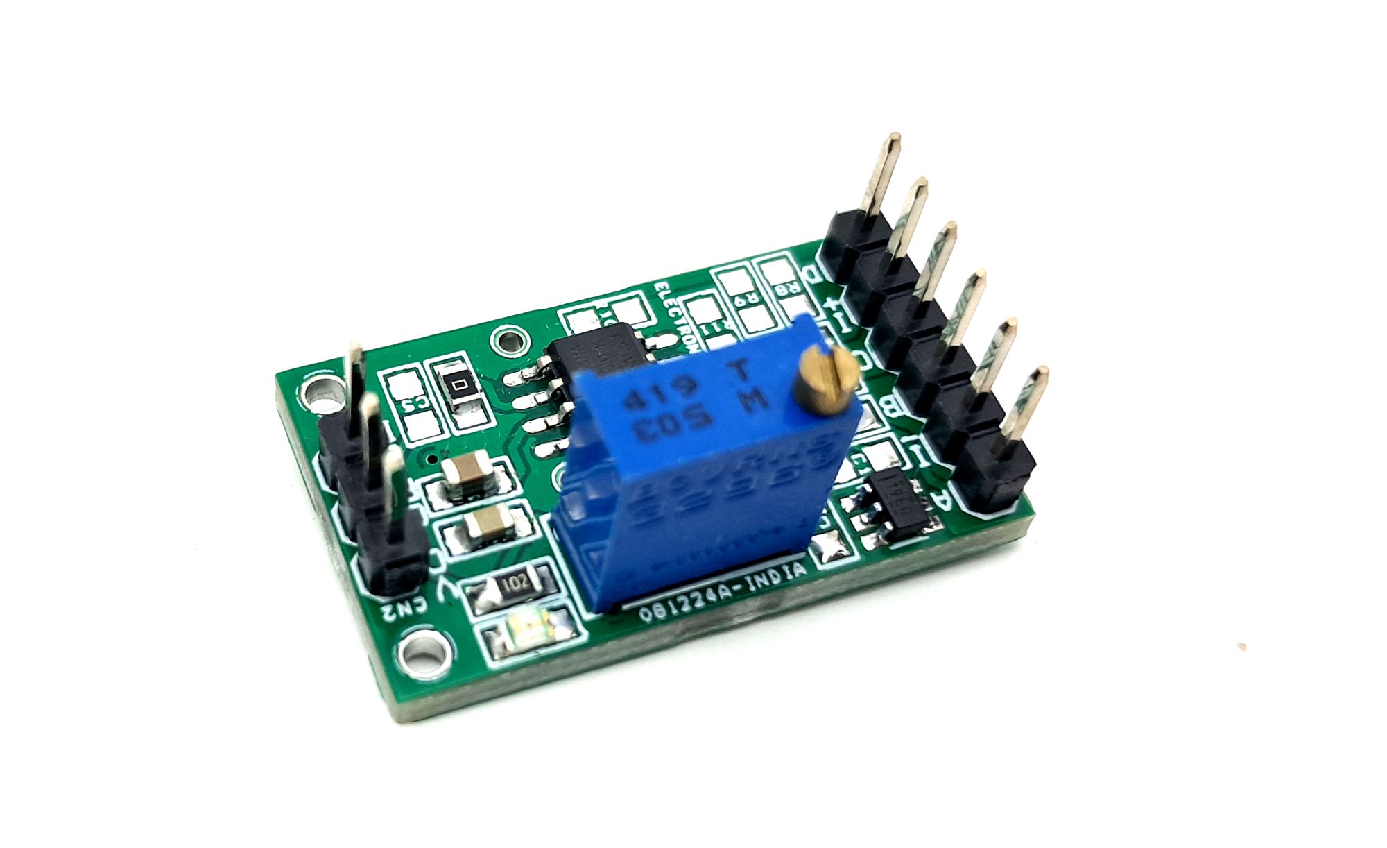
INA122 Single Supply Micropower Instrumentation Amplifier Module
This low-noise INA122 precision instrumentation amp is ideal for portable data acquisition. It supports single-supply (2.2V to 12V), features an on-board 2.5V reference, adjustable gain (10-10000), and is adaptable for strain gauge/pressure sensors.
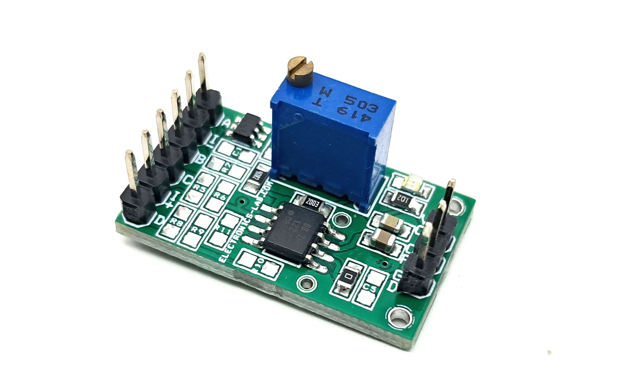
This project is a precision instrumentation amplifier board based on the INA122 chip, designed for accurate and low-noise differential signal acquisition. Here are the key features and specifications.
Key Features
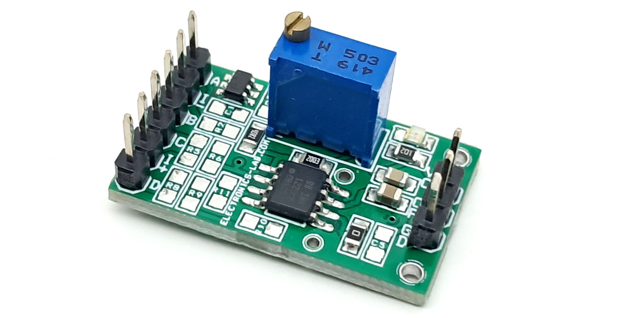
- INA122 chip with 2 OPAMP design for excellent performance and low quiescent current (60uA).
- Suitable for portable instrumentation and data acquisition systems.
- Can be operated with a single supply voltage.
- Optional components provided to create a resistive bridge amplifier for pressure sensor or strain gauge sensors.
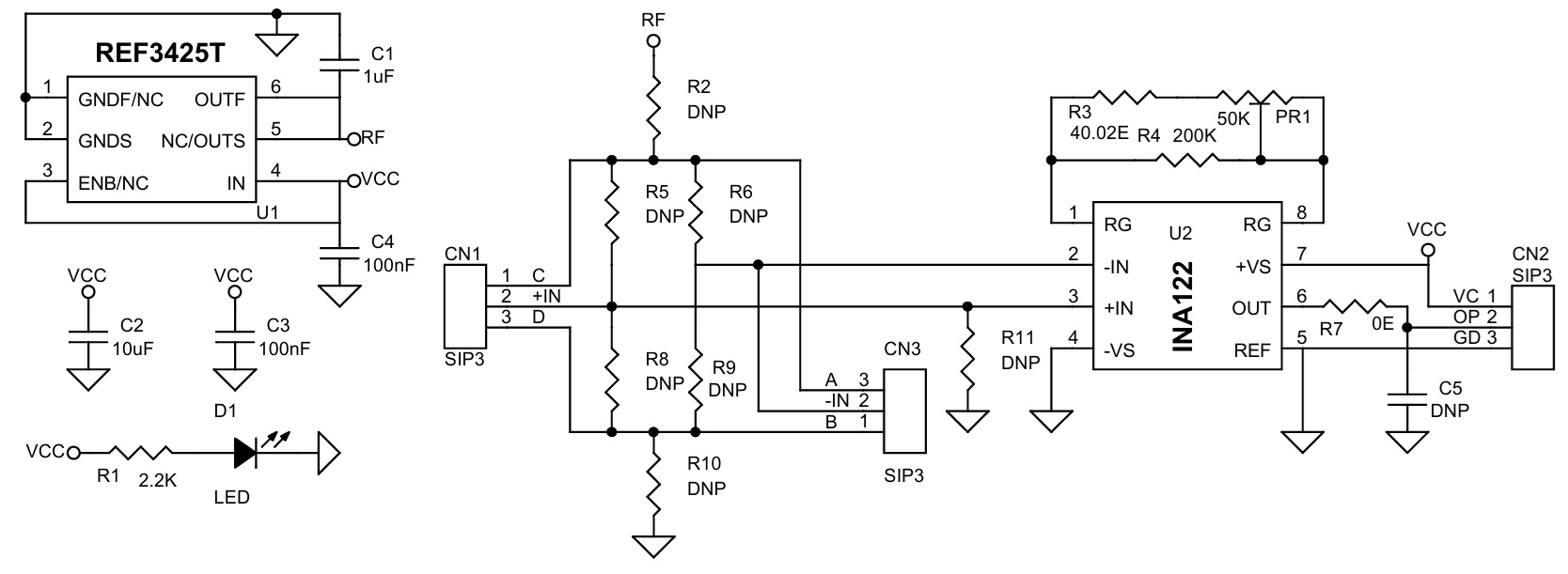
- On-board reference chip REF3425 provides a 2.5V reference voltage, with the option to use REF3450 for a 5V reference.
- Power Supply 2.2V to 12V DC, Single Supply (Supports up to 36V Read Note)
- On Board options for Resistive Pressure Sensor or stain gauge Sensor
- Header Connector for Inputs/Sensor and Output
- On Board Power LED
- Gain Adjust 10 to 10000 Using PR1
- On Board Trimmer Potentiometer for Gain Adjust
- PCB Dimensions: 28.10 x 16.35 mm
Specifications
- Power supply range: 2.2V to 36V (limited to 12V if using the on-board reference generator chip U1).
- Gain adjustment: Trimmer potentiometer PR1 allows gain adjustment in the range of 10 to 10000.
- Special case for gain 5: Doesn’t install R3, R4, and PR1.
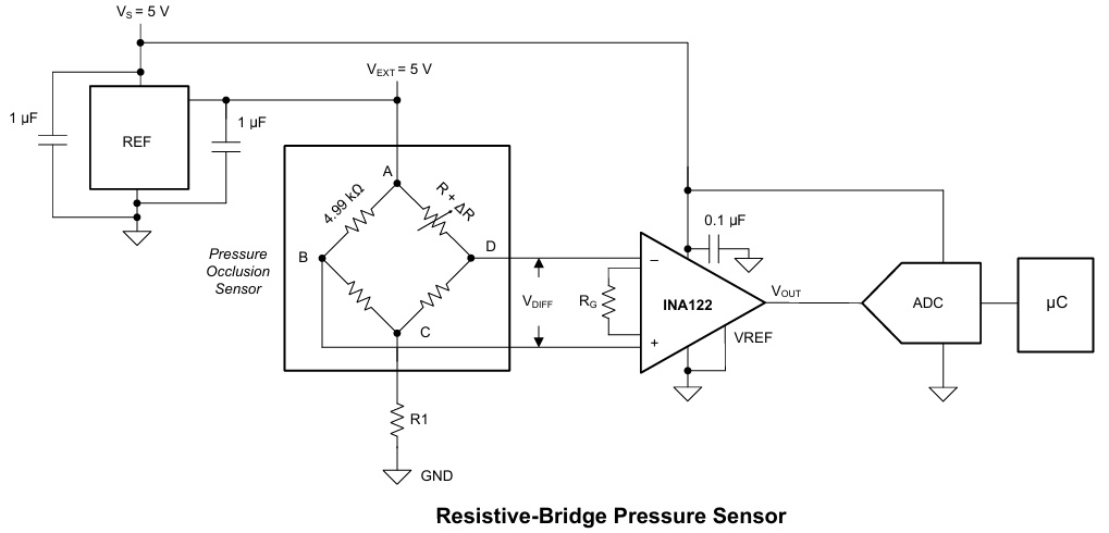
Resistive Bridge Amplifier for Pressure Sensor
The board offers optional components to create a resistive bridge amplifier, suitable for pressure sensors or strain gauge sensors. To configure the amplifier, use the values specified in the sensor’s datasheet. All resistors are of SMD 0805 size, and the inputs are connected to a header connector, allowing for easy connection to external sensors.
The on-board reference chip, REF3425, provides a 2.5V reference voltage to the resistive bridge. Alternatively, users can opt for the REF3450 chip to obtain a 5V reference voltage.
To create a resistive bridge amplifier, install the following components:
- Resistors: R2, R5, R6, R8, R9, R10, and R11
- Connectors: CN1 and CN3 for sensor connection
By following these steps, users can easily configure the resistive bridge amplifier to work with their specific pressure sensor or strain gauge sensor, ensuring accurate and reliable measurements.
Input Protection
The inputs of the INA122 are protected with internal diodes connected to the power supply rails. The diodes clamp the applied signal to prevent damaging the input circuitry. If the input signal source voltage exceeds the power supplies by more than 0.3V, limit the source current with a series input resistor to less than 5mA to protect the internal clamp diodes. Some signal sources are inherently current-limited and do not require limiting resistors.
Output Current Range
Output sourcing and sinking current values versus the output voltage ranges are shown in the Typical Characteristics section of data sheet. The positive and negative current limits are not equal. Positive output current sourcing can drive moderate to high load impedance. Battery operation normally requires the careful management of power consumption to keep load impedance very high throughout the design.
INA122 Overview
The INA122 is a monolithic, precision instrumentation amplifier featuring a two-op-amp design. This design saves power, making it ideal for portable instrumentation and data acquisition systems. The amplifier’s gain can be set from 5 V/V to 10,000 V/V using a single external resistor, RG.
The internal design consists of two identical op-amps, A1 and A2. Depending on the load conditions, their outputs can swing to within approximately 100 mV of the power supply rails.
Internal Overload Conditions
A common and easily overlooked overload condition occurs when the internal op-amp, A2, saturates. This happens if its output voltage is driven beyond its swing limits. Since A2 is an internal node that cannot be measured directly, this saturation can be difficult to detect.
Even if A2 is saturated, A1 may continue to operate linearly, giving the false appearance of normal operation while producing an invalid output voltage. To avoid this, you should calculate the expected voltage at A2’s output to ensure it remains within its linear range.
Single-Supply Operation
Single-supply instrumentation amplifiers present unique design challenges. A standard two-op-amp topology using common single-supply op-amps would not perform correctly. For instance, if both inputs were at 0 V, the outputs of A1 and A2 would also need to be 0 V. However, any small positive voltage applied to the non-inverting input (VIN+) would require A2’s output to swing below 0 V, which is impossible without a negative power supply.
To solve this, the INA122 uses precision level-shifting buffers on its inputs. This shifts both inputs up by approximately 0.5 V. Through the feedback network, this in turn shifts the output of A2 up by about 0.6 V. As a result, A2’s output remains within its linear operating range even when the external inputs and the reference voltage (VREF) are at the ground rail (0 V).
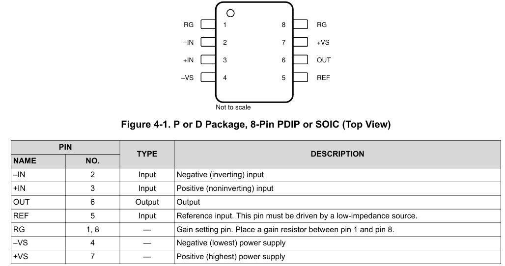
Gain Resistor (RG) Pins
A key consequence of this input level-shifting is that the voltages at the gain resistor pins (RG, pins 1 and 8) are not equal to the input pin voltages (pins 2 and 3). This is generally not a concern, as these pins are typically only used for connecting the external gain-setting resistor.
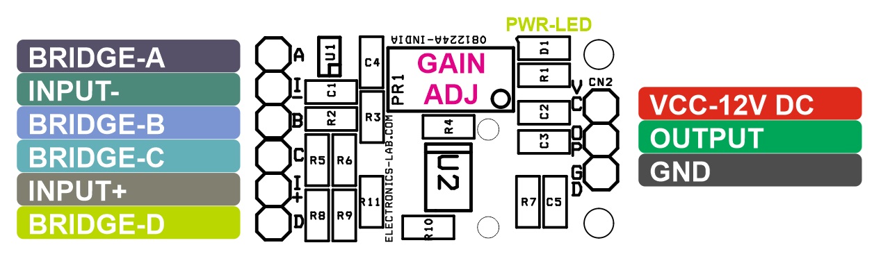
Connections
- CN1: Pin 1 = Optional Bridge C, Pin 2 = + IN, Pin 3 = Optional Bridge D
- CN2: Pin 1 = VCC, Pin 2 = Output, Pin 3 = GND
- CN3: Pin 1 = Optional Bridge A, Pin 2 = IN-, Pin 3 = Optional Bridge B
- D1: Power LED
- PR1: Gain Adjust Trimmer
Schematic
Parts List
| NO | QNTY. | REF. | DESC. | MANUFACTURER | SUPPLIER | SUPPLIER PART NO |
|---|---|---|---|---|---|---|
| 1 | 3 | CN1,CN2,CN3 | 3 PIN MALE HEADER PITCH 2.54MM | WURTH | DIGIKEY | 732-5316-ND |
| 2 | 1 | C1 | 1uF/50V CERAMIC SMD SIZE 0805 | YAGEO/MURATA | DIGIKEY | |
| 3 | 1 | C2 | 10uF/50V CERAMIC SMD SIZE 0805 | YAGEO/MURATA | DIGIKEY | |
| 4 | 2 | C3,C4 | 100nF/50V CERAMIC SMD SIZE 0805 | YAGEO/MURATA | DIGIKEY | |
| 5 | 8 | R2,R5,C5,R6,R8,R9,R10,R11 | DNP | |||
| 6 | 1 | D1 | LED RED SMD SIZE O805 | OSRAM | DIGIKEY | 475-1278-1-ND |
| 7 | 1 | PR1 | 50K MULTI-TURN TRIMMER POT | BOURNS | DIGIKEY | 3296W-503LF-ND |
| 8 | 1 | R1 | 2.2K 5% SMD SIZE 0805 | YAGEO/MURATA | DIGIKEY | |
| 9 | 1 | R3 | 40.02E 1% SMD SIZE 0805 | YAGEO/MURATA | DIGIKEY | |
| 10 | 1 | R4 | 200K 1% SMD SIZE 0805 | YAGEO/MURATA | DIGIKEY | |
| 11 | 1 | R7 | 0E SMD SIZE 0805 | YAGEO/MURATA | DIGIKEY | |
| 12 | 1 | U1 | REF3425T | TI | DIGIKEY | 296-47490-1-ND |
| 13 | 1 | U2 | INA122 | TI | DIGIKEY | 296-38945-1-ND |
Connections
INA122 Pinout
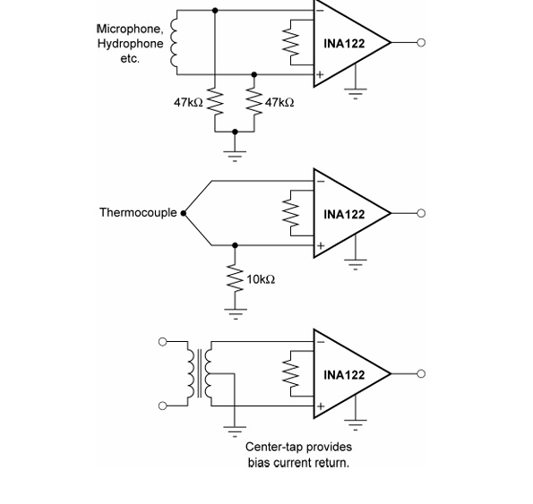
Example Application
Basic Application Schematics
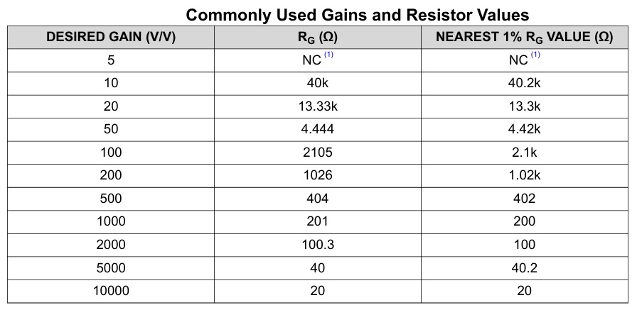
Gain Resistor Selection
Gerber View