Photodiode light level detection with Arduino
In today’s article, we will implement a photodiode light-level detection with Arduino UNO. We will use Arduino IDE software for coding and a ready-made photodiode module as the sensor.
In today’s article, we will implement a photodiode light-level detection with Arduino UNO. We will use Arduino IDE software for coding and a ready-made photodiode module as the sensor. It is one of those modules easily obtainable in any retailer that sells Arduino stuff.
What we want to achieve is light-level detection, so that we can implement line-following robots, light/dark detection, and so on.
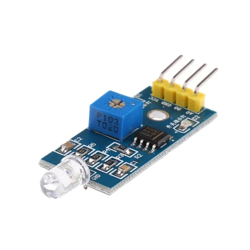
The module in question can be seen in the picture below and uses a dual-operational amplifier LM393. One of the internal OPAMPs (operation amplifiers) is used for amplification and the other for comparison. This is so that the module has double outputs: analog and digital.
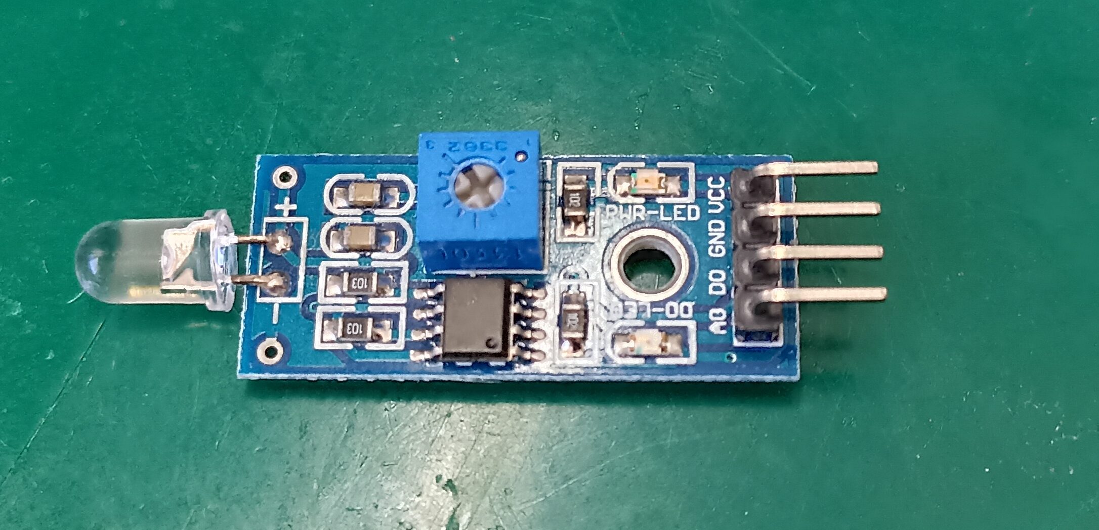
There is a small potentiometer visible on the board, that serves to adjust the threshold level for going from “0” to “1” in the “D0” pin. Pin “A0” on the other hand serves as the analog value output from the LM393, straight from the photodiode sensor.
The Sensor and Application circuit
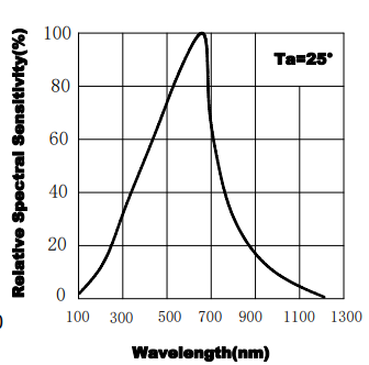
Speaking about the sensor, I found a probable candidate to be our photodiode of choice for this board. It came to be the SGPD5650C8 from Shuguan, whose datasheet is here.
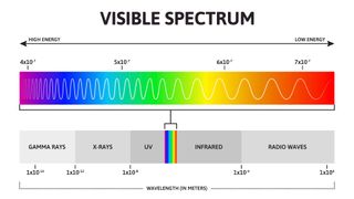
The device has its peak detection spectral response at red (650nm (nanometers)), but it does detect the full spectrum (380nm to 750nm) of visible light. Below you can see its spectral response along with the visible light full spectrum, for comparison.
I was not able to find the full electronics schematic for this module but instead found a probable candidate for the analog part of it. This part uses only one of the two LM393 operational amplifiers.
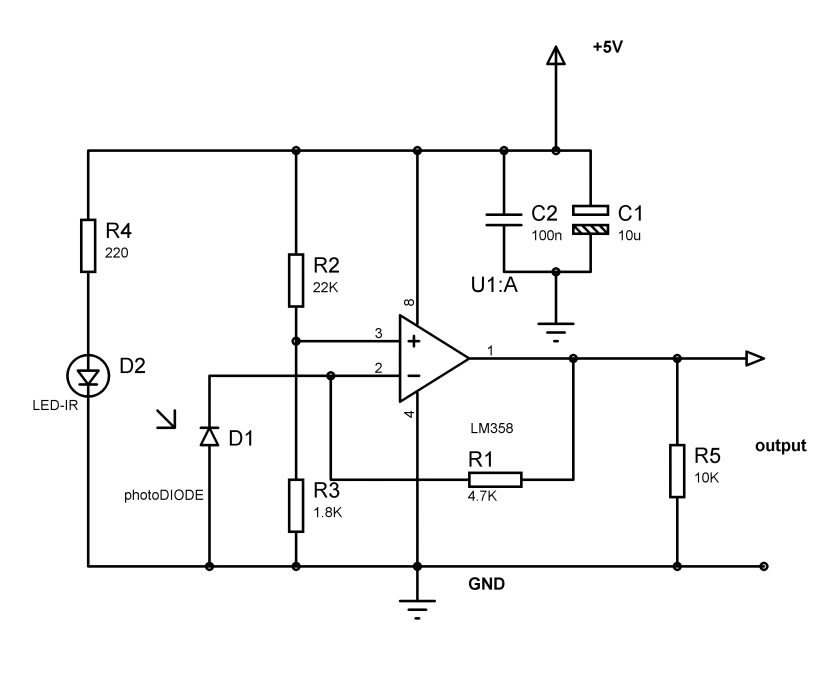
Configuration name is a non-inverting amplifier, whose gain is dictated by R1 and the photodiode D1. There is a comparison voltage level dictated by R2 and R3. Resistor R5 is used for stability factor only within the output pin.
The Circuit
Today’s experiment is simple in terms of the circuit, all we have is a photodiode module connected to our Arduino UNO. Connection happens via the analog input A1 pin. Besides that, we also need to supply the module with +5V and GND. The complete schematic diagram is below.
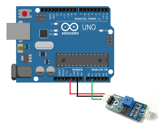
We will not be adjusting the small potentiometer, since it serves for the digital output only. Our interest resides in the analog output part of the fun.
Even those boards that work with 3.3V, for example, the ESP32 or Arduino UNO R4 minima, Raspberry Pi Pico 2, will do the job.
Code (Firmware)
We will use the Arduino IDE software to program our Arduino UNO for this project. I am using version 2.3.3 nightly (which is already a bit outdated), but you can use any 2.x.x version you want. You could even use platformIO or Arduino cloud IDE if you want, as long as you know your way around it.
One more time saying that the code for this example will be extremely simple. I do not remember writing such a simple code before. Besides defining setup() and loop(), there are only three more lines to it.
The full code is below. In the setup() I initialize our serial communication to 9600 bits per second. In the loop() I nested two functions, there is the analogRead(A1) to read the analog pin. It is inside the Serial.println() to print such read values to the Arduino IDE serial monitor.
void setup() {
  // Put your setup code here, to run once:
  Serial.begin(9600);
}


void loop() {
  // Put your main code here, to run repeatedly:


  Serial.println(analogRead(A1));
  delay(500);
}
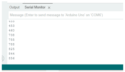
I then execute such functions every 500ms (0.5 seconds) and repeat indefinitely. So you see something like the image below in your Arduino IDE serial monitor:
Results
Notice the analog reading values in the image above, they vary quite a lot. This is due to my positioning of hand on top of the sensor and blocking the light to it. Just to make sure we are on the same page, such values will vary between 0 and 1023. This represents the 10-bit resolution of the analog inputs of Arduino UNO.
Analyzing such results, I can finally present you with the applications of such sensors. It can be used for things like a line-following robot, to detect a black electric tape line on the ground. That can also be used to detect parts of the human body, like hands or arms. It could even detect parts and pieces of hardware, like day-to-day objects (presence or absence).
I made a video showing you everything you need to know about this sensor. Enjoy it, and please comment below if you have any questions.