Real Time Clock and Temperature Monitor using DS3231 Module
Hi guys, welcome to this tutorial. One of the most important things everyone wants to keep track of daily is, time and with easy to use platforms like the arduino it is very easy to create your own timepiece and in the case of this tutorial add a temperature monitor to it.
Hi guys, welcome to this tutorial. One of the most important things everyone wants to keep track of daily is, time and with easy to use platforms like the arduino it is very easy to create your own timepiece and in the case of this tutorial add a temperature monitor to it.
For this tutorial, we will be creating a real-time clock and temperature monitor using the simple and easy to use DS3231 module.
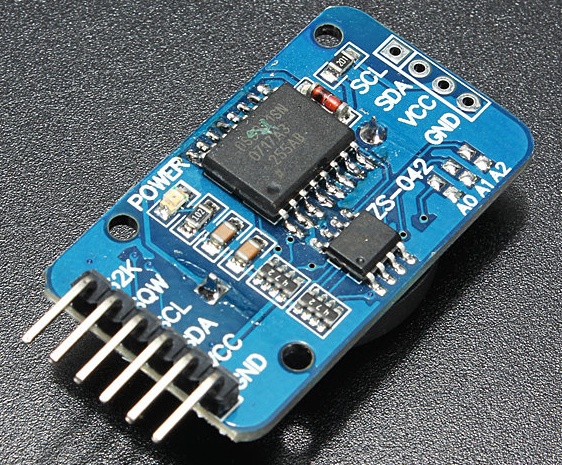
The DS3231 is a very low power RTC chip, it has the ability to keep time with incredible accuracy such that even after power has been disconnected from your product, it can run for years on a connected coin cell battery. This module has the ability to communicate via I2C or SPI but for this tutorial we will be using the I2C mode for communications between our arduino and the DS3231. The module also comes with a quite accurate temperature sensor which we will be using to get temperature readings. The collected temperature and clock data is then displayed on the 16×2 LCD via the Arduino.
Required Components
The following components will be needed for this tutorial. They can be purchased via the links attached.
1. DS3231 module
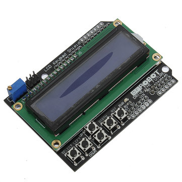
2. 16×2 LCD module or shield
3. Arduino Mega, or any other variation
4. Jumper wires
5. Potentiometer (if not using an LCD shield)
6. Small Breadboard
Schematics
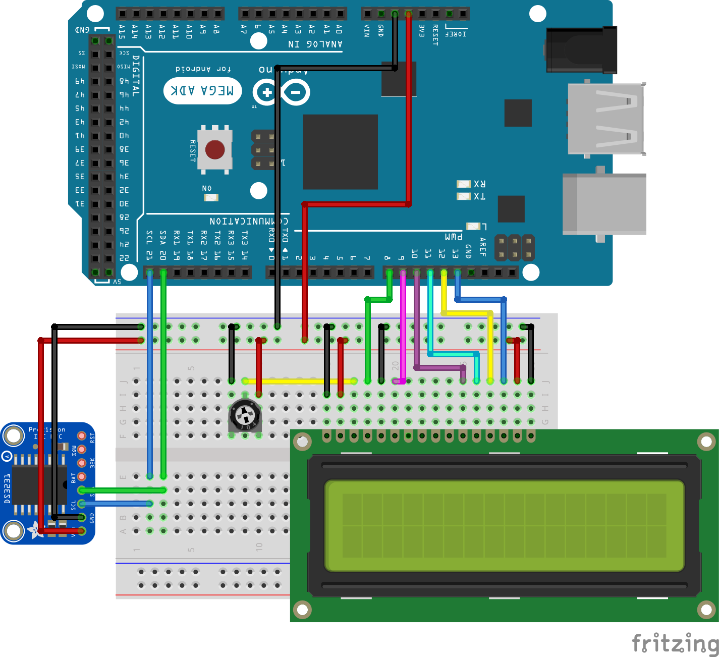
Connect all components as shown in the Fritzing schematics below, kindly note the LCD connection will not be needed if using the shield.
Since the DS3231 is going to communicate via I2C then its I2C pins will be connected to the arduino’s I2C (SDA and SCL) pins which on the mega are located on pin A0 and A1 or pin 20 (SDA) and 21 (SCL) of the arduino mega.
RTC - Arduino MEGA
SDA - Pin 20(SDA)
SCL - Pin 21(SCL)
VCC - 5v
GND - GND
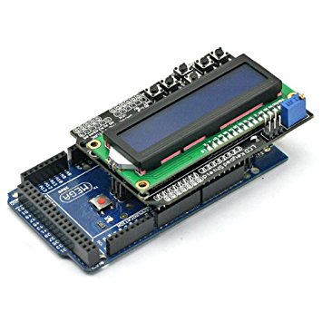
Next connection is between the LCD and the Arduino. If you are using the screen and keypad shield whose link is attached above, all you will just need to do is plug it in to your arduino as shown below.
If not then you can connect it as described in the schematics and illustrated below.
LCD - ARDUINO
pin 1 - GND
pin 2 - 5v
pin 3 - Middle pin of the Potentiometer(check Schematics)
pin 4 - D8
Pin 5 - GND
pin 6 - D9
pin 7-10 - GND or nothing
pin 11 - D10
pin 12 - D11
pin 13 - D12
pin 14 - D13
pin 15 - VCC
pin 16 - GND
Code
With the connections done, lets jump into writing the code.
The first thing we need to do is to download the arduino library for the ds3231 RTC. The library can be found here and is also attached at the end of this project. Rename the library to “RTC” and install it, by copying and pasting into the Arduino libraries folder.
Launch the Arduino IDE and copy in the Attached code.
To do a break down of the code, the first thing we do in the code is to include the libraries that carry some of the dependencies needed for our code to run. The Libraries include wire.h to enable I2C communication, Ds3231.h and rtc_ds3231.h to enable the RTC to work and the Liquidcrystal.h which makes it easy for us to work with the LCD.
//Written by Nick Koumaris
//info@educ8s.tv
//educ8s.tv

#include <Wire.h>
#include "ds3231.h"
#include "rtc_ds3231.h"
#include <LiquidCrystal.h>
The next thing is to declare the LCD pins and move into the setup function
The code is a modified version of the example found in the arduino library. The first thing we will be doing with the code is setting the time of the ds3231. The time is set using this line under the setup section.
Serial.println("Setting time");
parse_cmd("T302911604102014",16);
2014 is the year,
10 is the month
04 is the day of the month
6 is the day of the week
11 is hour of the day (its 11 am here)
29 is the minute
30 is the seconds
you can change this to match your current date when setting the time.
The device does not come with time preset but after setting it once, the action will no longer be needed.
The next thing after this is to move into the loop function. The loop function displays the time and temperature on the LCD after querying the DS3231 module.
void loop()
{
    char in;
    char tempF[6];
    float temperature;
    char buff[BUFF_MAX];
    unsigned long now = millis();
    struct ts t;

    // show time once in a while
    if ((now - prev > interval) && (Serial.available() <= 0)) {
        DS3231_get(&t); //Get time
        parse_cmd("C",1);
        temperature = DS3231_get_treg(); //Get temperature
        dtostrf(temperature, 5, 1, tempF);

        lcd.clear();
        lcd.setCursor(1,0);

        lcd.print(t.mday);

        printMonth(t.mon);

        lcd.print(t.year);

        lcd.setCursor(0,1); //Go to second line of the LCD Screen
        lcd.print(t.hour);
        lcd.print(":");
        if(t.min<10)
        {
          lcd.print("0");
        }
        lcd.print(t.min);
        lcd.print(":");
        if(t.sec<10)
        {
          lcd.print("0");
        }
        lcd.print(t.sec);

        lcd.print(' ');
        lcd.print(tempF);
        lcd.print((char)223);
        lcd.print("C ");
        prev = now;
    }


    if (Serial.available() > 0) {
        in = Serial.read();

        if ((in == 10 || in == 13) && (recv_size > 0)) {
            parse_cmd(recv, recv_size);
            recv_size = 0;
            recv[0] = 0;
        } else if (in < 48 || in > 122) {;       // ignore ~[0-9A-Za-z]
        } else if (recv_size > BUFF_MAX - 2) {   // drop lines that are too long
            // drop
            recv_size = 0;
            recv[0] = 0;
        } else if (recv_size < BUFF_MAX - 2) {
            recv[recv_size] = in;
            recv[recv_size + 1] = 0;
            recv_size += 1;
        }

    }
}
The next block of code is the parse_cmd function that was used to set the time.
void parse_cmd(char *cmd, int cmdsize)
{
    uint8_t i;
    uint8_t reg_val;
    char buff[BUFF_MAX];
    struct ts t;

    //snprintf(buff, BUFF_MAX, "cmd was '%s' %d\n", cmd, cmdsize);
    //Serial.print(buff);

    // TssmmhhWDDMMYYYY aka set time
    if (cmd[0] == 84 && cmdsize == 16) {
        //T355720619112011
        t.sec = inp2toi(cmd, 1);
        t.min = inp2toi(cmd, 3);
        t.hour = inp2toi(cmd, 5);
        t.wday = inp2toi(cmd, 7);
        t.mday = inp2toi(cmd, 8);
        t.mon = inp2toi(cmd, 10);
        t.year = inp2toi(cmd, 12) * 100 + inp2toi(cmd, 14);
        DS3231_set(t);
        Serial.println("OK");
    } else if (cmd[0] == 49 && cmdsize == 1) {  // "1" get alarm 1
        DS3231_get_a1(&buff[0], 59);
        Serial.println(buff);
    } else if (cmd[0] == 50 && cmdsize == 1) {  // "2" get alarm 1
        DS3231_get_a2(&buff[0], 59);
        Serial.println(buff);
    } else if (cmd[0] == 51 && cmdsize == 1) {  // "3" get aging register
        Serial.print("aging reg is ");
        Serial.println(DS3231_get_aging(), DEC);
    } else if (cmd[0] == 65 && cmdsize == 9) {  // "A" set alarm 1
        DS3231_set_creg(DS3231_INTCN | DS3231_A1IE);
        //ASSMMHHDD
        for (i = 0; i < 4; i++) {
            time[i] = (cmd[2 * i + 1] - 48) * 10 + cmd[2 * i + 2] - 48; // ss, mm, hh, dd
        }
        boolean flags[5] = { 0, 0, 0, 0, 0 };
        DS3231_set_a1(time[0], time[1], time[2], time[3], flags);
        DS3231_get_a1(&buff[0], 59);
        Serial.println(buff);
    } else if (cmd[0] == 66 && cmdsize == 7) {  // "B" Set Alarm 2
        DS3231_set_creg(DS3231_INTCN | DS3231_A2IE);
        //BMMHHDD
        for (i = 0; i < 4; i++) {
            time[i] = (cmd[2 * i + 1] - 48) * 10 + cmd[2 * i + 2] - 48; // mm, hh, dd
        }
        boolean flags[5] = { 0, 0, 0, 0 };
        DS3231_set_a2(time[0], time[1], time[2], flags);
        DS3231_get_a2(&buff[0], 59);
        Serial.println(buff);
    } else if (cmd[0] == 67 && cmdsize == 1) {  // "C" - get temperature register
        Serial.print("temperature reg is ");
        Serial.println(DS3231_get_treg(), DEC);
    } else if (cmd[0] == 68 && cmdsize == 1) {  // "D" - reset status register alarm flags
        reg_val = DS3231_get_sreg();
        reg_val &= B11111100;
        DS3231_set_sreg(reg_val);
    } else if (cmd[0] == 70 && cmdsize == 1) {  // "F" - custom fct
        reg_val = DS3231_get_addr(0x5);
        Serial.print("orig ");
        Serial.print(reg_val,DEC);
        Serial.print("month is ");
        Serial.println(bcdtodec(reg_val & 0x1F),DEC);
    } else if (cmd[0] == 71 && cmdsize == 1) {  // "G" - set aging status register
        DS3231_set_aging(0);
    } else if (cmd[0] == 83 && cmdsize == 1) {  // "S" - get status register
        Serial.print("status reg is ");
        Serial.println(DS3231_get_sreg(), DEC);
    } else {
        Serial.print("unknown command prefix ");
        Serial.println(cmd[0]);
        Serial.println(cmd[0], DEC);
    }
}
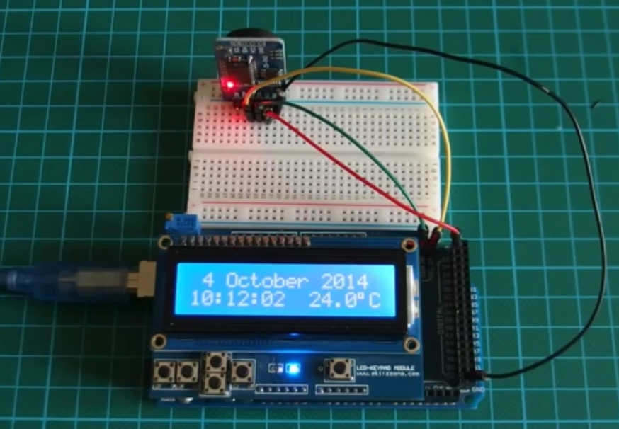
After uploading the code for the first time, the time setting part in the setup() is then commented out and the code can be uploaded again.
You should then see something like the image below.
A youtube video on how the project works can be found here. The video tutorial is created by educ8s.tv channel
The source code, library and other files can be downloaded from here RTCCODE
That’s it guys!, let me know if you have any questions, I will be glad to help.
thank you a lot. I want to do the same thing but with arduino uno not mega how to make the architecture (wires…).
Well in fact i don’t why you post things that don’t work. To begin with, the libraries names are bad ds3231, when it should be DS3231, and i can’t find the rtc_ds3231 library anywhere, among other things. Anyway, lest be serious
Hi Macondo!
thanks for your comments. Libraries get updated and a whole lot of things get swapped out. I believe that is what you are currently experiencing. If you go through the video, you will see that this works. Maybe watching the video might help you see where you got things wrong?
regards.
Hi, I know this is an old thread now but I’d like to use a Wemos D1 Mini which only has 8 digital pins. Can this be easily translated in the code? I’d also like to use a photo resistor in place of the potentiometer, as it is for a car clock.
Compilation error: Error: 2 UNKNOWN: exit status 1
After so long, this tutorial is no longer good, the original library has been modified and no longer working.
As indicated in previous comments it’s getting difficult to know which one to use as a replacement.
I strongly recommend to fix it or remove it to avoid wasting other’s people time.
Adafruit has a similar working tutorial that I’ve found easy and time effective