Multipurpose Motor Driver Shield for OLEDUINO v2
BD60210FV Shield: OLEDUINO-V2 driver for 1 stepper, 2 DC motors, or 4 solenoids. Compact design for versatile control.
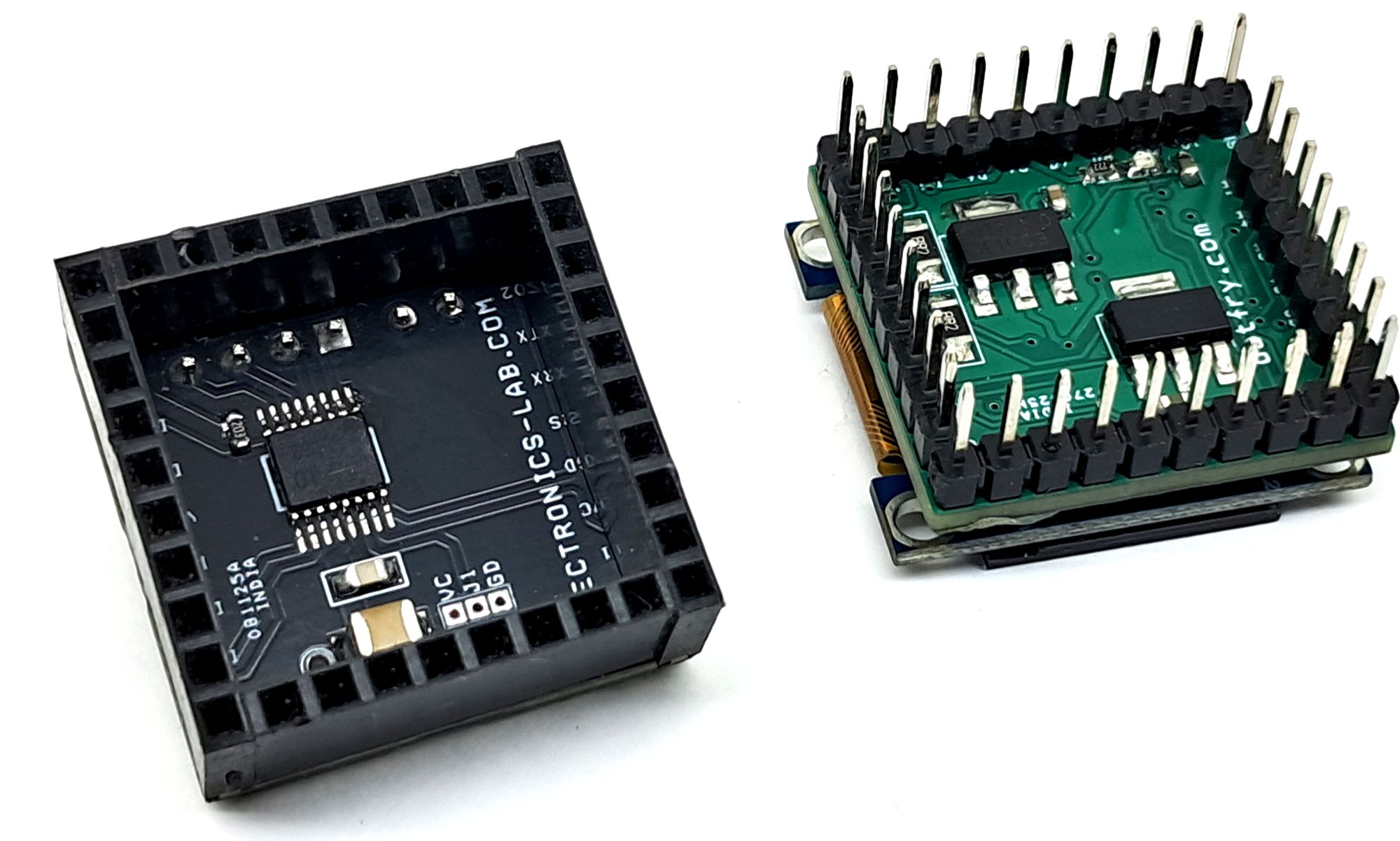
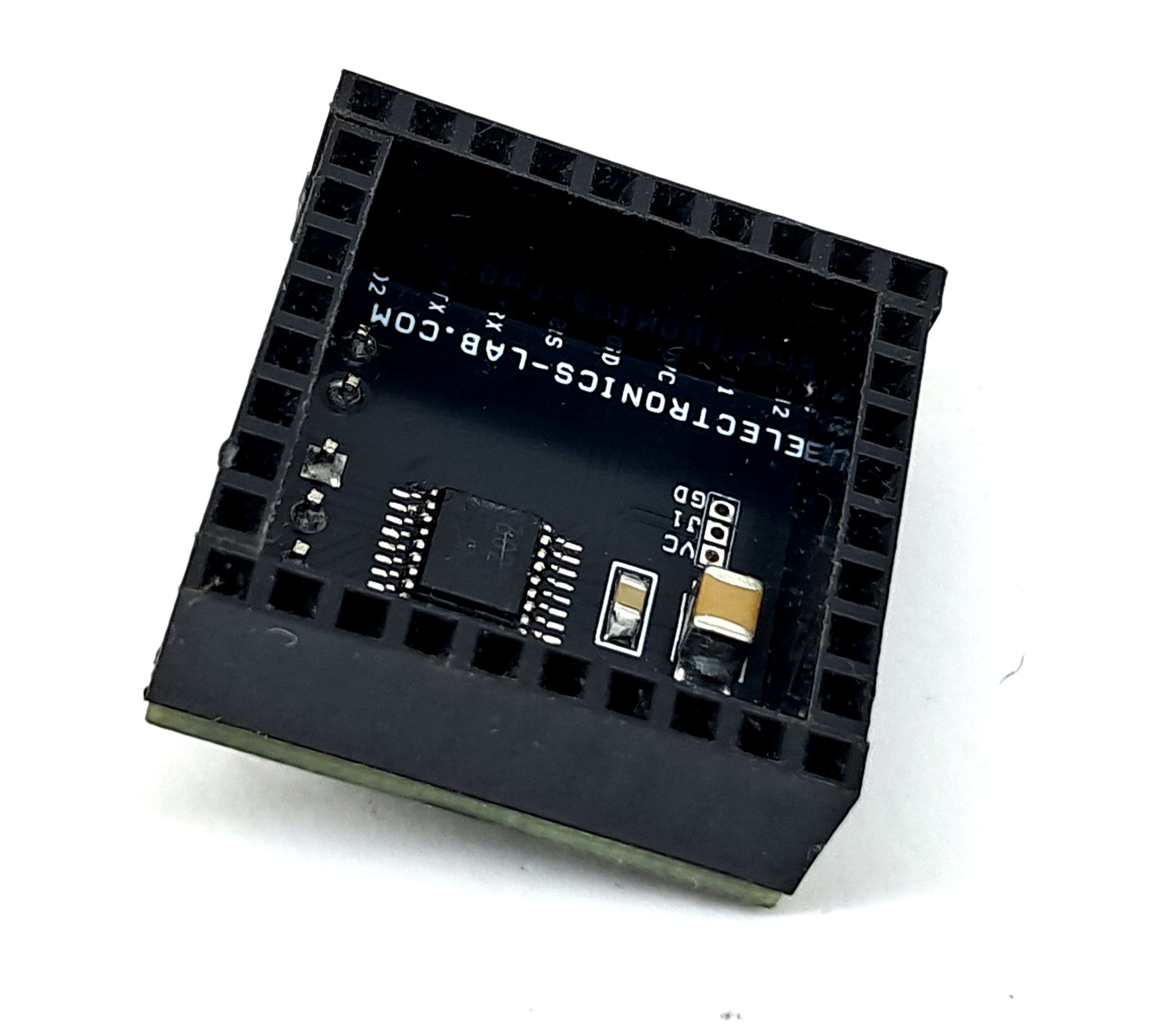
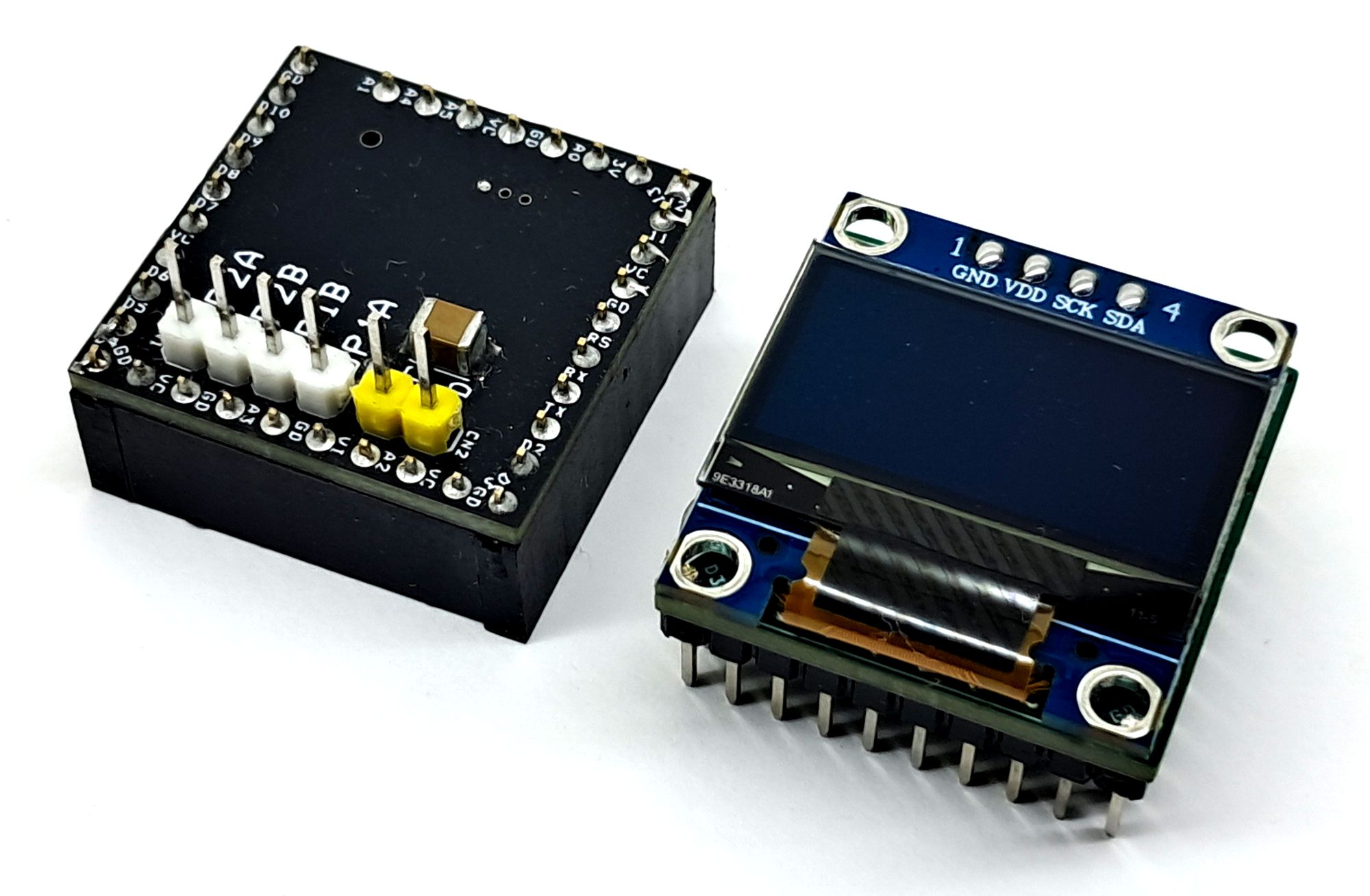
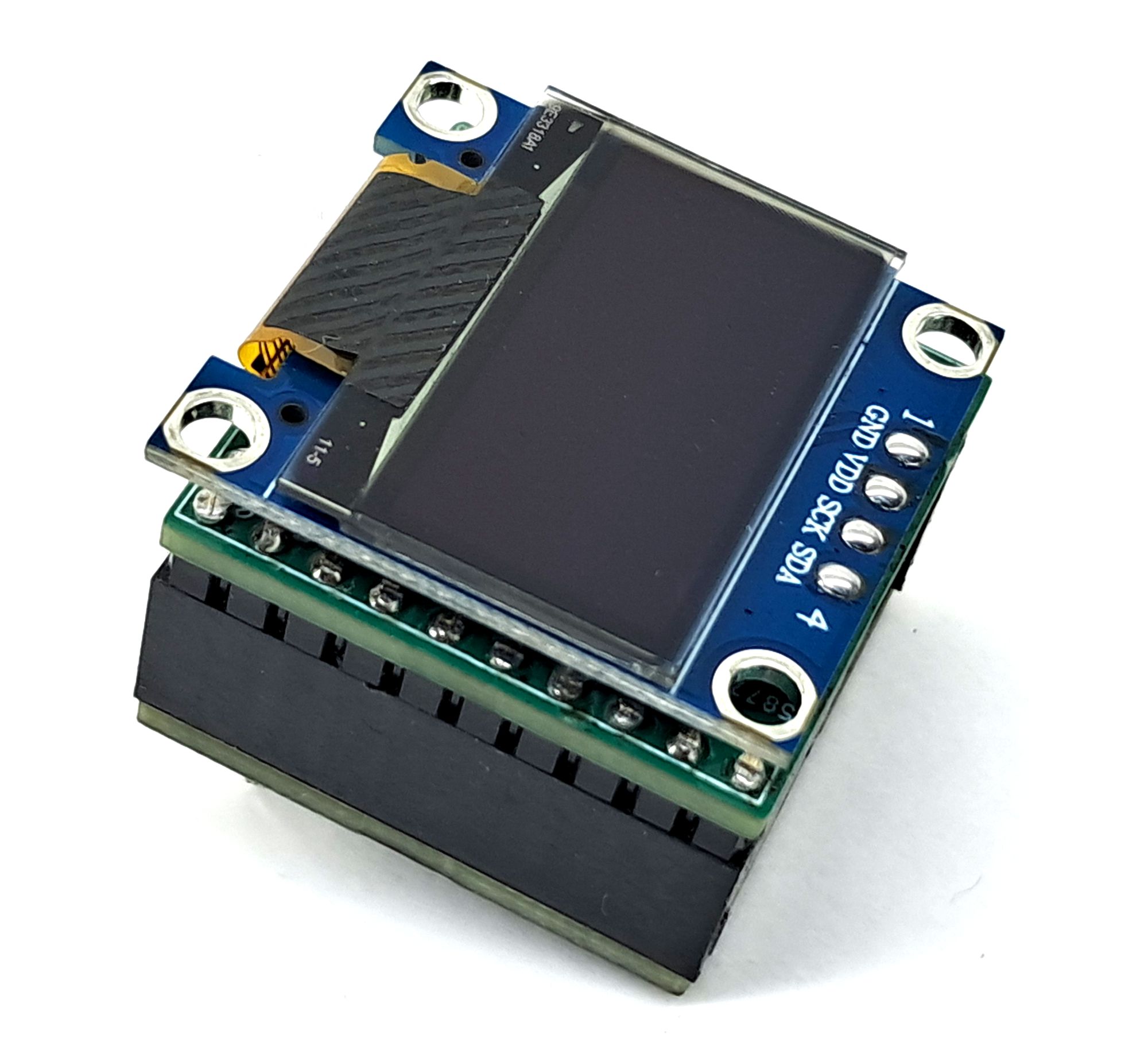
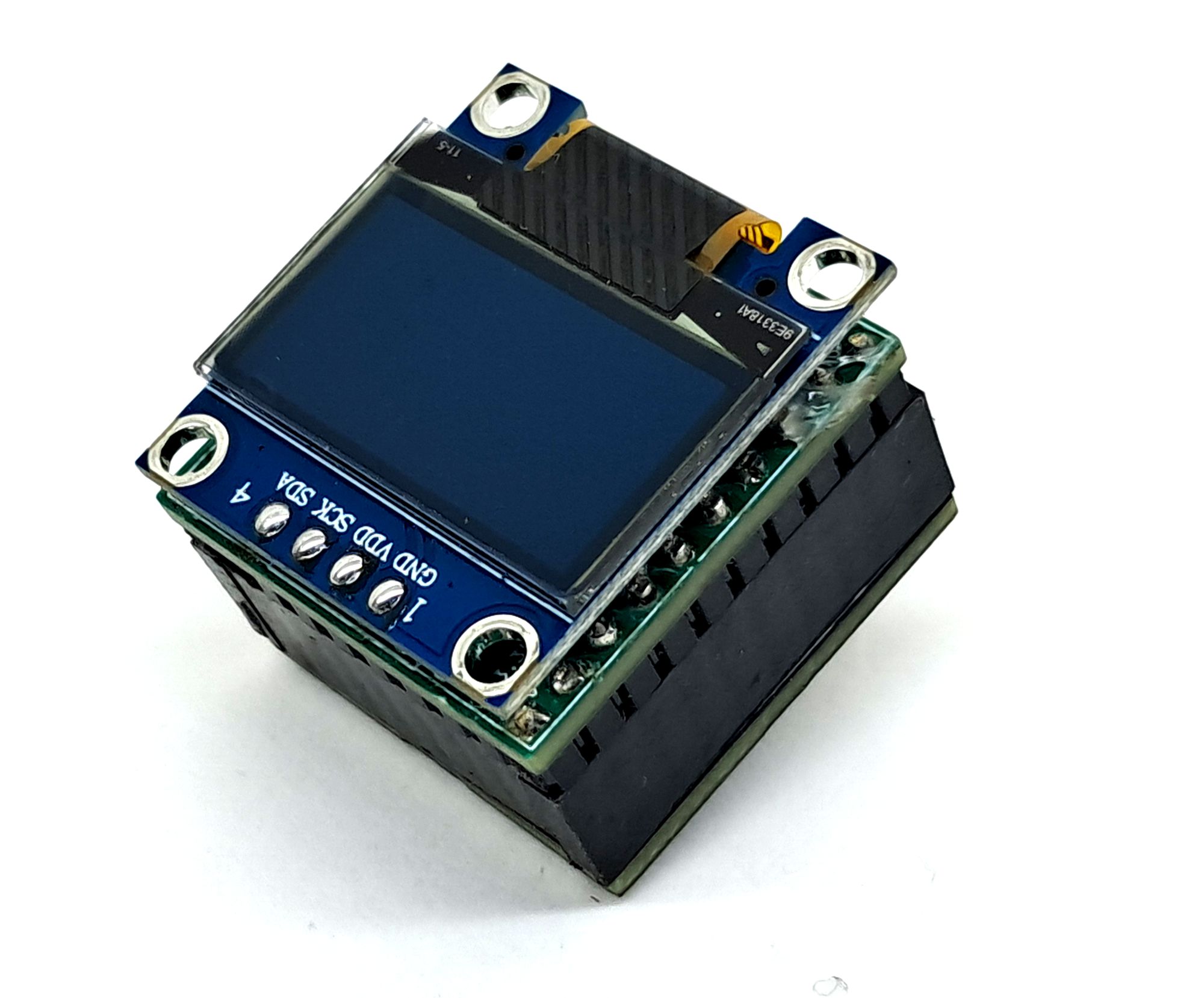
This multi-purpose motor driver shield is built around the BD60210FV motor driver IC. It is designed specifically for the OLEDUINO-V2 board, which features an onboard OLED display. This compact shield can be used to drive small bipolar stepper motors, two bidirectional brushed DC motors, and 4 solenoids.
The shield is capable of driving two brushed DC motors up to 1A continuous current with a supply voltage range of 8 V to 12 V. A key advantage of this shield is its seamless integration with the OLEDUINO-V2, allowing real-time display of speed, direction, and other operational information.
Features
- Single power supply input: 8 V to 12 V (rated voltage up to 20 V, see note)
- Rated output current (continuous): 1.0 A per phase
- Rated output current (peak): 4.0 A per phase
- Low ON-resistance DMOS outputs
- Forward, reverse, brake, and stop functions
- Power-save function
- Direct PWM control
- Full-step and half-step functionality (stepper motor mode)
- Built-in logic input pull-down resistors
- Cross-conduction prevention circuit
- Thermal shutdown (TSD)
- Over-current protection (OCP)
- Under-voltage lockout (UVLO)
- Ghost-supply prevention when power is disconnected
- Adjacent pin short-circuit protection
- PCB Dimensions 25.4 x 25.4 mm
Driving Examples
- 2 x brushed DC motors Bidirectional, 4 x Motors One Direction
- 1 x bipolar stepper motor
- 4 x Solenoids
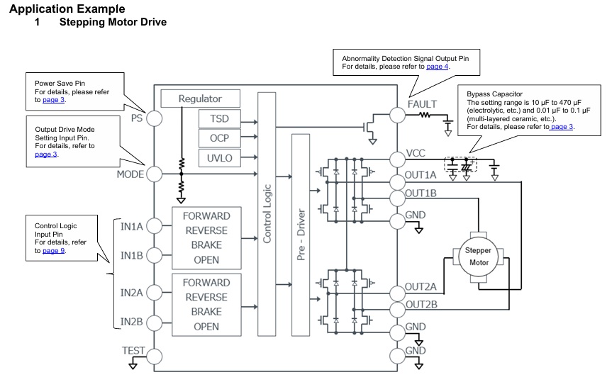
Stepper Motor Driver
The shield can drive a small bipolar stepper motor using its dual H-bridge configuration, supporting both full-step and half-step operation.
Brushed DC Motor Driver
The shield can drive four brushed DC motors in one directional and two bidirectional motor, with a load current of up to 1 A.
Solenoid Driver
The shield can also be used to drive four solenoids, making it suitable for a wide range of electromechanical applications.
Power Supply
The shield supports load voltages up to 12 V DC and can operate using a single power supply for both the OLEDUINO-V2 and the motor driver.
For higher-voltage motors (above 12 V and up to 18 V), a dual-supply configuration is required:
- 5 V to 12 V for the OLEDUINO-V2
- 12 V to 18 V for the motor driver
PS/Power Save Pin (Arduino A2)
The PS pin can make circuits in standby state and make motor output OPEN.
When PS = L to H, be careful because there is a delay of 40 μs (Max) before it is returned from standby state to normal state and the motor output become ACTIVE.
- PS Pin Low = Standby
- PS Pin High = Active
MODE/Drive Mode Setting pin (Solder Jumper J1)
This is a 3-value input pin that sets the output drive mode. Four drive modes can be set by combining the MODE and IN2A pins.
- Mode Low + IN2A X = 4 Pins Interface Mode
- Mode High + IN2A Low = 2 Pins Interface Mode
- Mode High + IN2A High = Parallel Bridge Interface Mode
- M(Open) + IN2A X = Half Bridge Interface Mode
FAULT/Abnormal State Detection Output Pin (Arduino D4)
If overcurrent protection (OCP) or thermal shutdown circuit (TSD) is activated, an abnormality detection signal will be output. This signal is connected to a D4 of OLEDUINO-V2 to shut down the system. The output format of this pin is open drain which is pulled up using R1 (10K Ohm) resistor and connected toD4 of OLEDUINO-V2. Protect Function (OCP or TSD), Normally this pin is high, goes low at event of OCP or TSD.
Thermal Shutdown (TSD)
This IC has a built-in thermal shutdown circuit as an overheat protection measure. When the IC chip temperature exceeds 175 °C (Typ), the motor output is set to OPEN. Also, when the temperature drops below 150 °C (Typ), it will automatically return to normal operation. However, even when the TSD is operating, if heat is continued to be applied from the outside, thermal runaway will occur and lead to destruction.
Over Current Protection (OCP)
This IC has a built-in over current protection circuit as a provision against destruction when the motor outputs are shorted each other or VCC-motor output or motor output-GND is shorted. This circuit latches the motor output to OPEN condition when the regulated current flows for 2 μs (Typ). It returns with power reactivation or a reset by the PS pin. The over current protection circuit’s only aim is to prevent the destruction of the IC from irregular situations such as motor output shorts and is not meant to be used as protection or security for the set. Therefore, sets should not be designed to take into account this circuit’s functions. After OCP operating, if irregular situations continue and the return by power reactivation or a reset by the PS pin, then OCP operates repeatedly, and the IC may generate heat or otherwise deteriorate. When the L value of the wiring is great due to the wiring being long, the motor outputs have shorted each other or VCC-motor output or motor output-GND is shorted, if the output pin voltage jumps up and the absolute maximum values can be exceeded after the over current has flowed, there is a possibility of destruction. Also, when current which is the output current rating or more and the OCP detection current or less flows, the IC can heat up to Tjmax = 150 °C exceeds and can deteriorate, so current which or more the output rating should not be applied.
Under Voltage Lock Out (UVLO)
This IC has a built-in under voltage lock out function to prevent false operation such as IC output during power supply under voltage is low. When the applied voltage to the VCC pin goes 5 V (Typ) or less, the motor output is set to OPEN. This switching voltage has a 1 V (Typ) hysteresis to prevent false operation by noise etc. Be aware that this circuit does not operate during power save mode.
The BD60210FV is a dual H-bridge motor driver capable of driving two DC brushed motors, one bipolar stepper motor, or up to four solenoid loads. It supports high-efficiency operation through direct PWM control.
The device provides an abnormal condition detection output (wired-OR), which signals the activation of protection circuits. This feature enhances system reliability and robustness in real-world applications.
Arduino Code
Arduino (OLEDUINO-V2) test code is provided to verify the functionality of the shield. The user can upload this code directly to the board. The test program sequentially drives all four motors one by one and displays the operating sequence on the OLED.
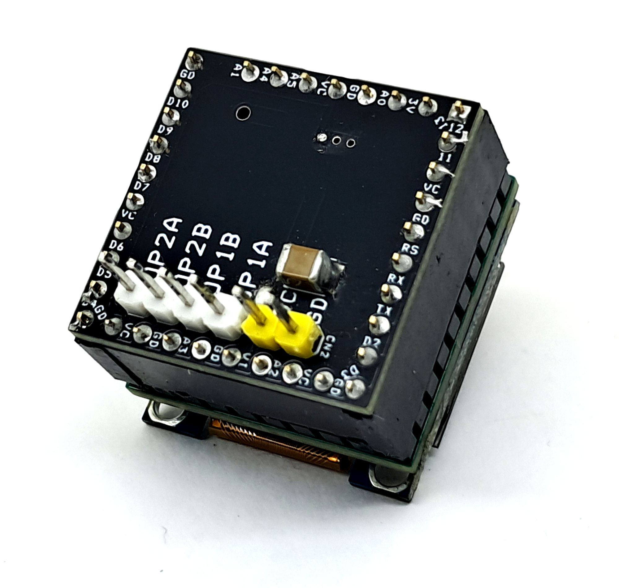
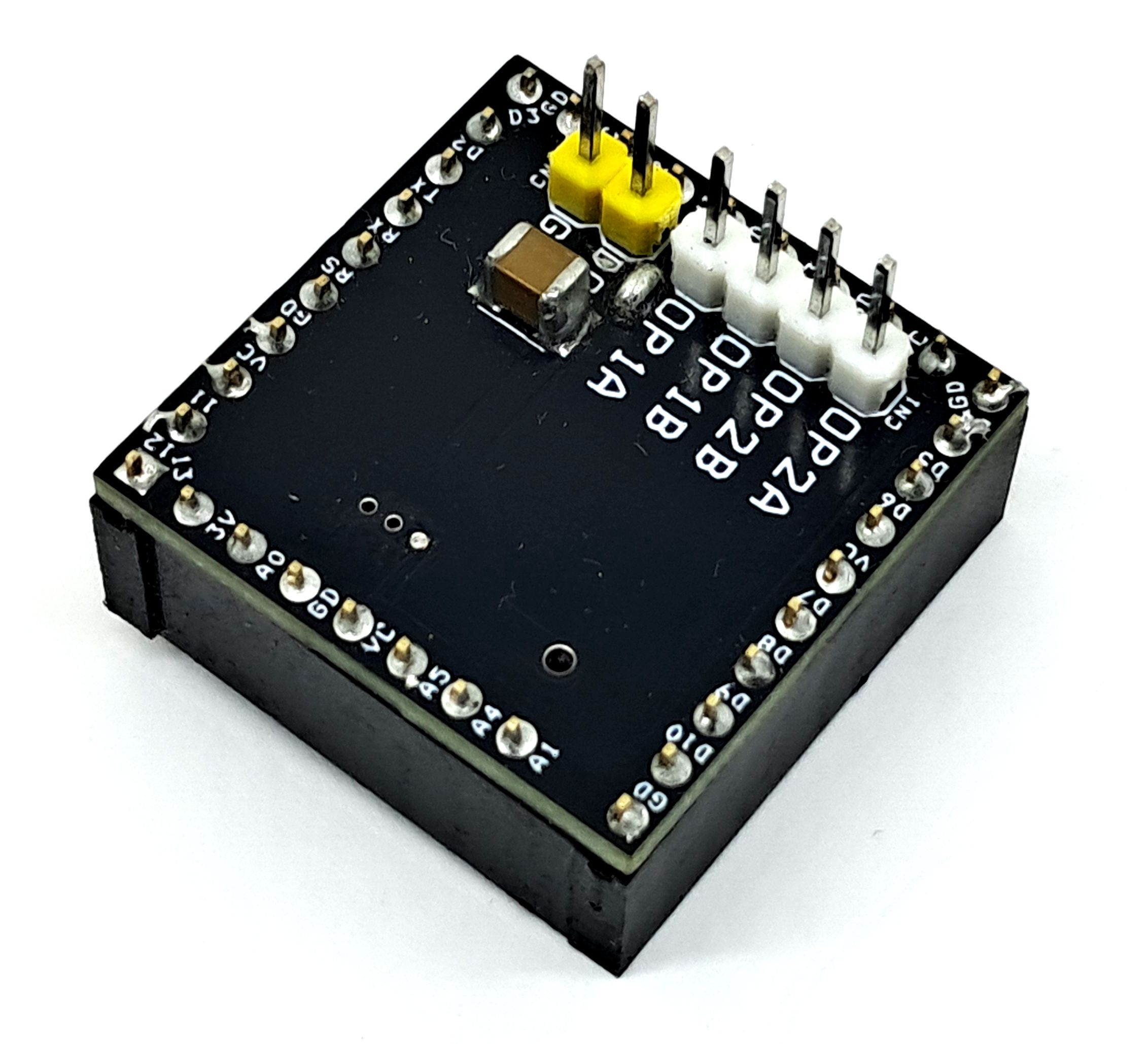
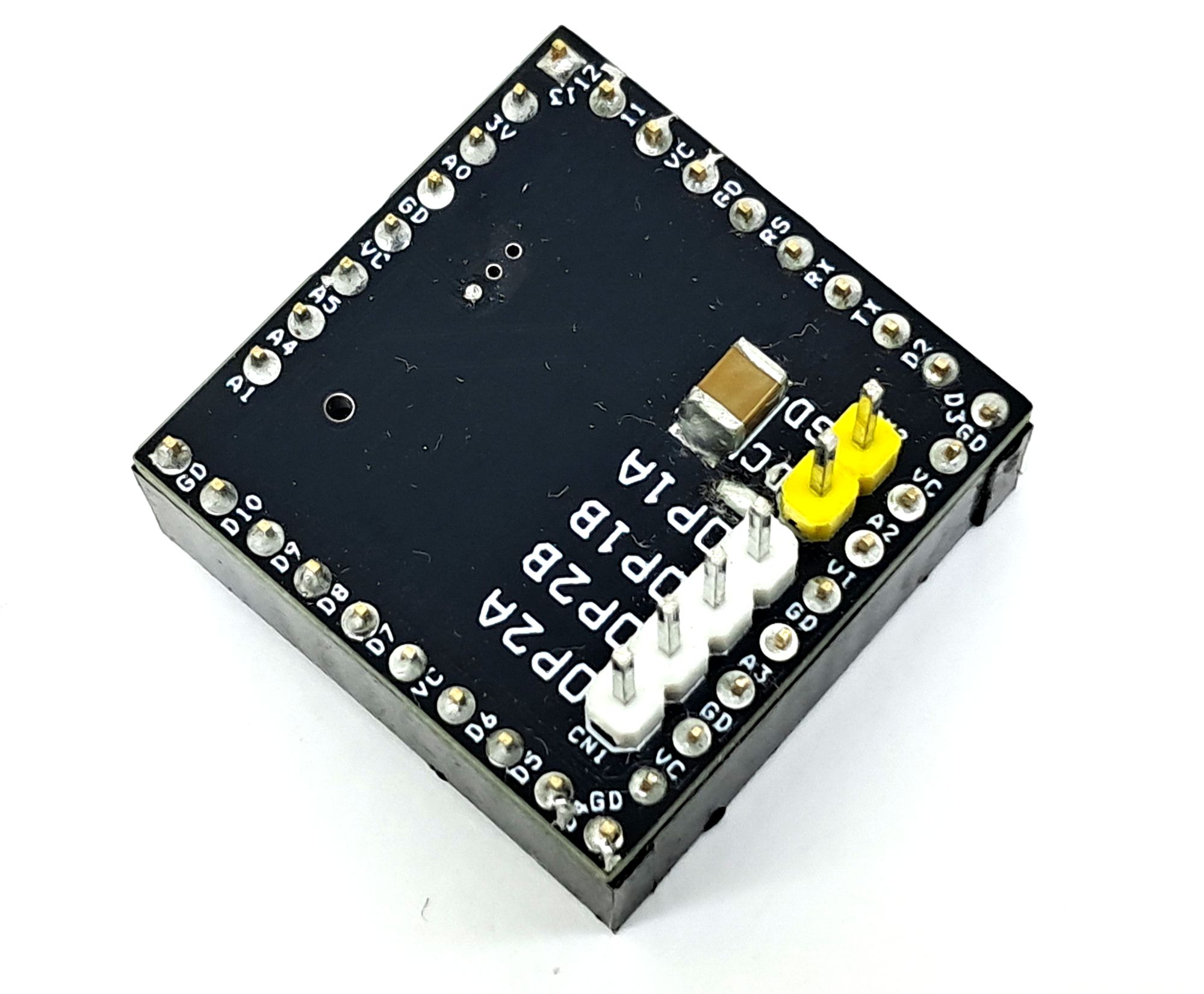
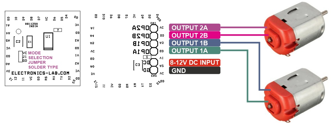
Connections
- CN1: Pin 1 = Output 1A, Pin 2 = Output 1B, Pin 3 = Output 2B, Pin 4 = Output 2A
- CN2: Pin 1 = 8V to 12V DC Power, Pin 2 = GND
- J1: Solder Type Jumper for Mode Selection
Schematic
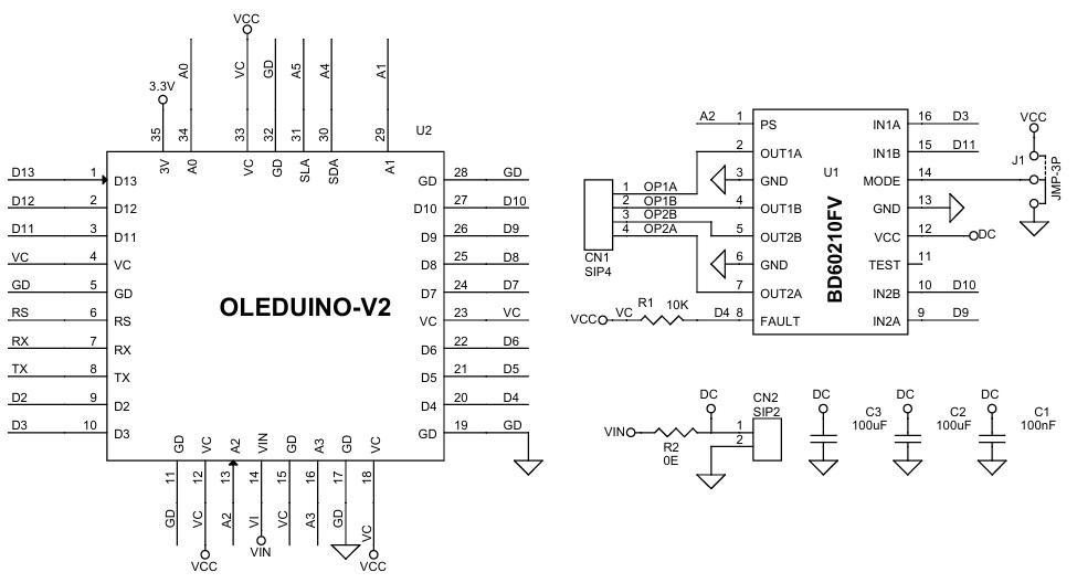
Parts List
| BOM | ||||||
|---|---|---|---|---|---|---|
| NO. | QNTY. | REF. | DESC. | MANUFACTURING | SUPPLIER | SUPPLIER PART NO |
| 1 | 1 | CN1 | 4 PIN MALE HDAER PITCH 2.54MM | WURTH | DIGIKEY | 732-5317-ND |
| 2 | 1 | CN2 | 2 PIN MALE HEADER PITCH 2.54MM | WURTH | DIGIKEY | 732-5315-ND |
| 3 | 1 | C1 | 100nF/50V CERAMIC SMD SIZE 0804 | YAGEO/MURATA | DIGIKEY | |
| 4 | 2 | C2,C3 | 100uF/25V CERAMIC SMD SIZE 1210 | YAGEO/MURATA | DIGIKEY | |
| 5 | 1 | J1 | SOLDER TYPE JUMPER PCB | |||
| 6 | 1 | R1 | 10K 5% SMD SIZE 0603 | YAGEO/MURATA | DIGIKEY | |
| 7 | 1 | R2 | 0E 5% SMD SIZE 0603 | YAGEO/MURATA | DIGIKEY | |
| 8 | 1 | U1 | BD60210FV | ROHM | DIGIKEY | 846-BD60210FV-E2CT-ND |
| 9 | 1 | U2 | 8 PIN FEMALE HEADER PITCH 2.54MM | WURTH | DIGIKEY | 732-61300811821-ND |
| 10 | 2 | U2 | 10 PIN FEMALE HEADER PITCH 2.54MM | WURTH | DIGIKEY | 732-2859-ND |
Connections
 Application Diagram
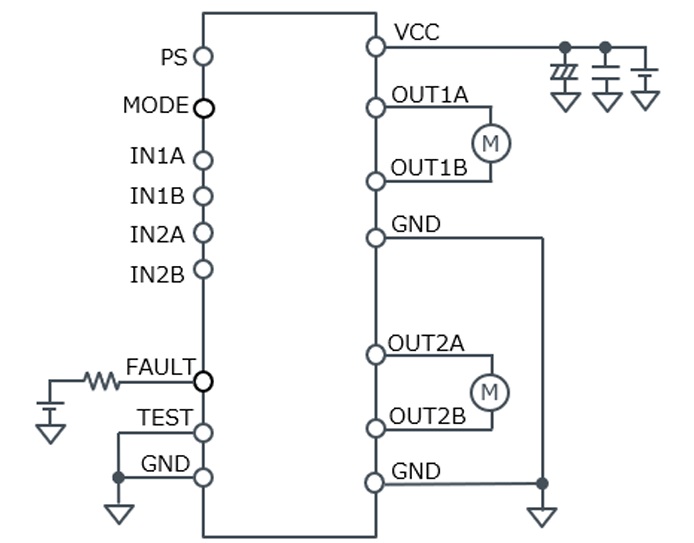
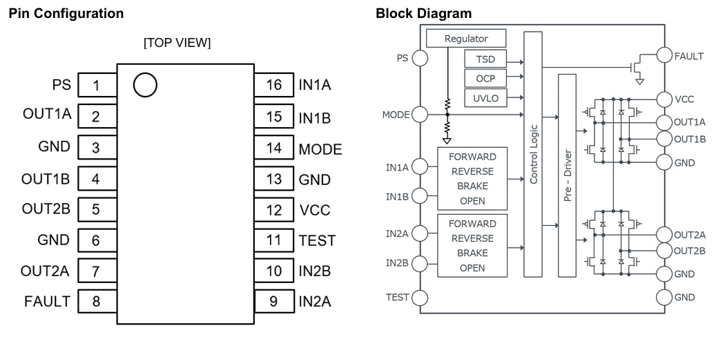
BD60210FV Block Diagram & Pin Configuration
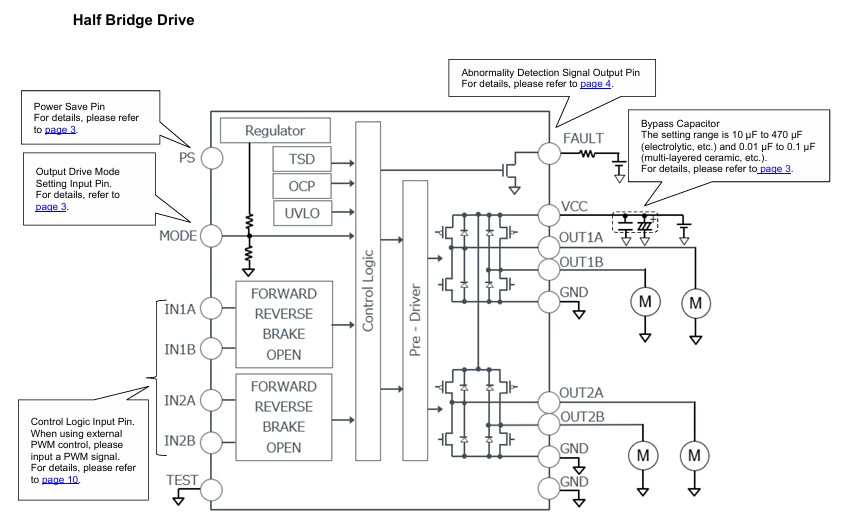
Half Bridge Diagram
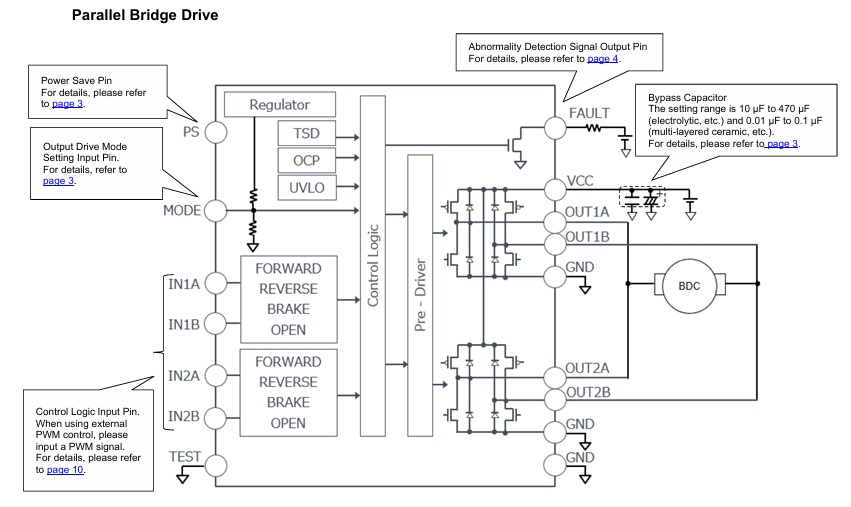
Parallel Bridge Diagram
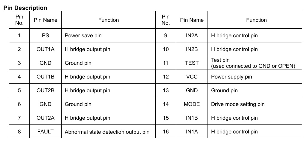
Pinout Description
Stepper Motor Drive Example Diagram