Under/Over Voltage and Current Protection Switch – High Current
LTC6102 Protection: UV/OV/UC/OC switch for loads up to 30A/48V. Arduino-ready for V/I sensing via ADC.
This simple project allows users to design an under-voltage, over-voltage, under-current, and over-current protection switch. It is a very useful system for safeguarding electrical loads against abnormal power or current conditions.
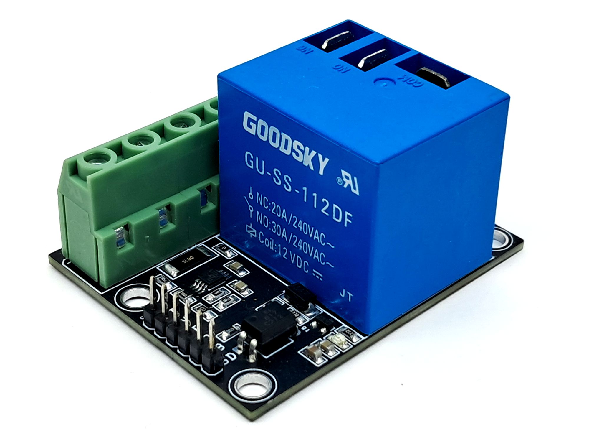
The project features a relay with optocoupler input, a current-sensing circuit based on the LTC6102 amplifier, a 6 mΩ shunt resistor, and a voltage divider network for voltage feedback. It is primarily designed for low-voltage and high-current applications up to 10A, but the relay can handle loads up to 30A at supply voltages up to 48 V.
The system can be easily controlled using an Arduino or other microcontrollers. Voltage and current feedback signals are fed into the microcontroller’s ADC pins for measurement, while the relay can be switched using a 5 V control signal from the processor.
Features
- Supply 12V DC Relay Circuit
- Load Supply 5 To 48V, Load Current Up to 10A (Max 12A)
- Relay Triger Input 5V 20mA
- Current Sensor Output 0.2V/A (10A =2V)
- Load Up to 10Amps (Max12A), Load Supply Up to 48V DC
- Load Power Supply Feedback 4.364 @ 48V, 0.455 @ 5V Supply
- 4 x 4mm PCB Mounting Holes
- PCB Dimensions 56.52 x 45.88mm
Over/Under Current Switch
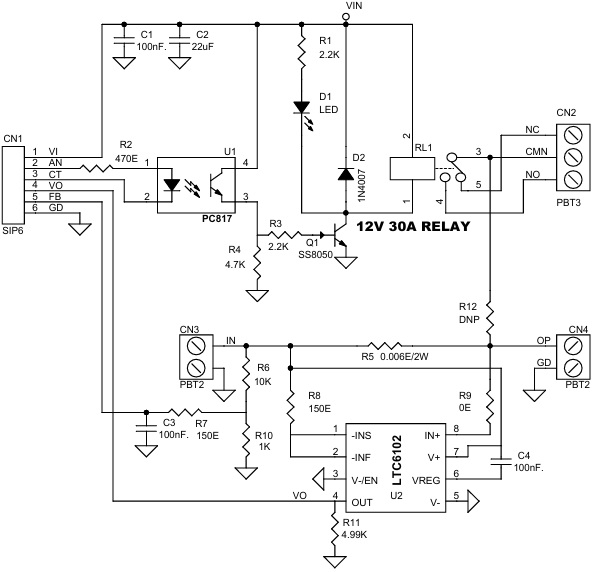
The LTC6102 current-sense amplifier measures the voltage across the shunt resistor and provides an output voltage proportional to the load current. This output can be read by the microcontroller’s ADC to implement over-current or under-current protection logic. on-board current-sense resistor R5 voltage-drop, provides a precision output voltage proportional to load current. The circuit includes scaling resistors R8 and R11 that program the gain of the circuit to 33.3V/V. The LTC6102 is powered from the same supply that the sense resistor is connected to and provides a ground referenced output. The LTC6102 can perform current measurements on supplies ranging from 5V to 48V. Since the output voltage is developed as a controlled current through a load resistance, ground loop errors can be eliminated by simply locating the load resistor at the destination point (subsequent signal processing such as A/D conversion). Remote loading can be evaluated by simply removing the on-board load resistor (R5).
Over/Under Voltage Switch
A resistor divider network, formed by R5 = 10 kΩ and R10 = 1 kΩ, is used to scale down the load voltage for ADC measurement. This feedback allows the controller to detect both over-voltage and under-voltage conditions. At 48 V input, the divider provides approximately 4.364 V, and at 5 V input, about 0.455 V. These resistor values can be modified to suit different voltage ranges as required by the application.
Operations
An Over/Under Voltage and Current Protection Switch can be designed using a combination of voltage divider resistors for voltage feedback, the LTC6102 current sense amplifier for current feedback, and a relay for switching the load on or off at preset threshold levels.
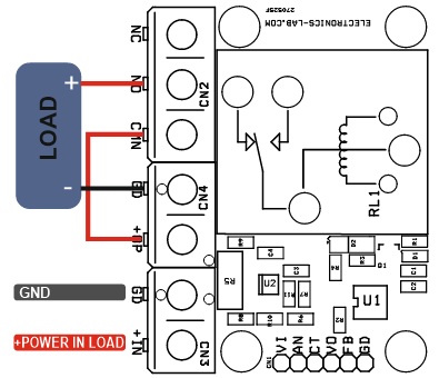
The board can be interfaced with an Arduino or other microcontroller. The voltage and current feedback signals connect to the ADC inputs, while the optocoupler output connects to a digital pin to control the relay and enable or disable the load. Relay Normally open and Normally closed contacts are open can be route through external wring.
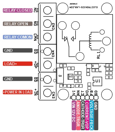
Connections
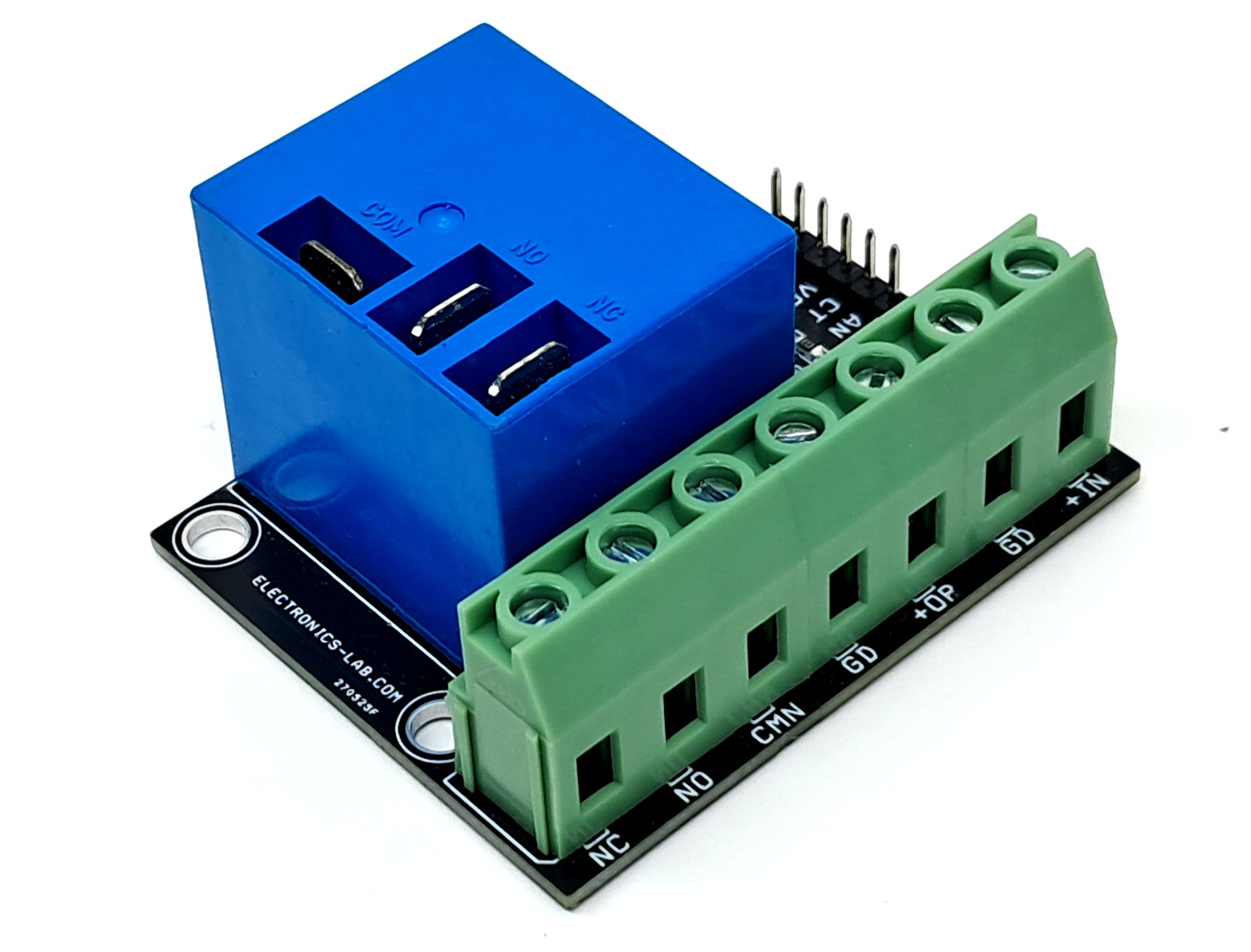
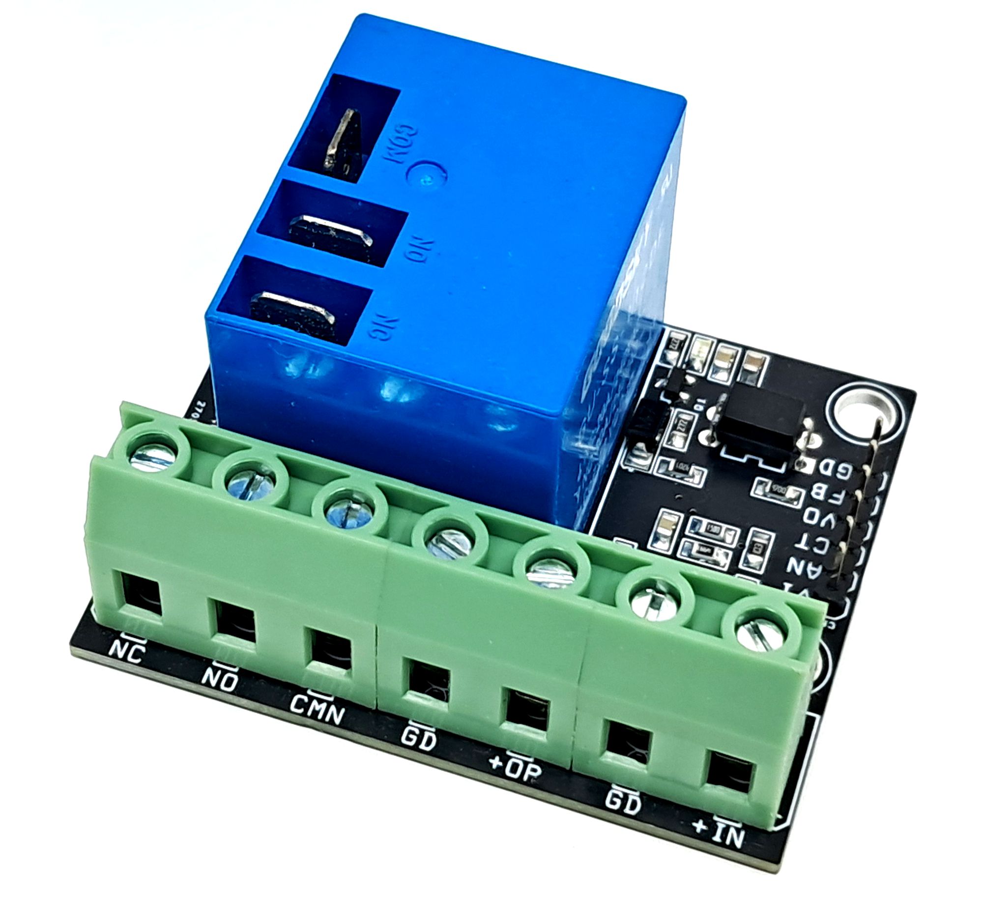
- CN1: Pin 1 = VIN 12V DC Relay Power, Pin 2 = Optocoupler Anode, Pin 3 = Optocoupler Cathode, Pin 4 = Current Feedback Output (VO), Pin 5 = Voltage Feedback, Pin 6 = GND
- CN2 Relay Contacts: Pin 1 = Relay Normally Closed, Pin 2 = Relay Common. Pin 3 = Normally Open
- CN3: Pin 1 = +Load Power Input, Pin 2 = GND
- CN4: Pin 1 = + Load Output, Pin 2 = GND
- D1: Relay LED
Schematic
Parts List
| NO. | QNTY. | REF. | DESC. | MANUFACTURER | SUPPLIER | SUPPLIER PART NO |
|---|---|---|---|---|---|---|
| 1 | 1 | CN1 | 6PIN MALE HEADER PITCH 2.54MM | WURTH | DIGIKEY | 732-5319-ND |
| 2 | 1 | CN2 | 3 PIN SCREW TERMINAL PITCH 7.62MM | WURTH | DIGIKEY | 732-691253410003-ND |
| 3 | 2 | CN3,CN4 | 2 PIN SCREW TERMINAL PITCH 5.08MM | WURTH | DIGIKEY | 732-691254410002-ND |
| 4 | 3 | C1,C3,C4 | 100nF/50V CERAMIC SMD SIZE 0805 | MURATA/YAGEO | DIGIKEY | |
| 5 | 1 | C2 | 22uF/25V CERAMIC SMD SIZE 0805 | MURATA/YAGEO | DIGIKEY | |
| 6 | 1 | D1 | LED RED SMD SIZE 0805 | OSRAM | DIGIKEY | 475-1278-1-ND |
| 7 | 1 | D2 | 1N4007 SMD | DIODE INC | DIGIKEY | S1MBDITR-ND |
| 8 | 1 | Q1 | SS8055 | UMW | DIGIKEY | 4518-SS8050CT-ND |
| 9 | 1 | RL1 | 12V 30A RELAY | PICKER COMPONENTS | DIGIKEY | 2634-PTRH-1C-12S-1-X-ND |
| 10 | 2 | R1,R3 | 2.2K 5% SMD SIZE 0805 | MURATA/YAGEO | DIGIKEY | |
| 11 | 1 | R2 | 470E 5% SMD SIZE 0805 | MURATA/YAGEO | DIGIKEY | |
| 12 | 1 | R4 | 4.7K 5% SMD SIZE 0805 | MURATA/YAGEO | DIGIKEY | |
| 13 | 1 | R5 | 0.006E/2W | YAGEO | DIGIKEY | YAG6098CT-ND |
| 14 | 1 | R6 | 10K 5% SMD SIZE 0805 | MURATA/YAGEO | DIGIKEY | |
| 15 | 2 | R7,R8 | 150E 5% SMD SIZE 0805 | MURATA/YAGEO | DIGIKEY | |
| 16 | 1 | R9 | 0E 5% SMD SIZE 0805 | MURATA/YAGEO | DIGIKEY | |
| 17 | 1 | R10 | 1K 5% SMD SIZE 0805 | MURATA/YAGEO | DIGIKEY | |
| 18 | 1 | R11 | 4.99K 1% SMD SIZE 0805 | MURATA/YAGEO | DIGIKEY | |
| 19 | 1 | R12 | DNP | MURATA/YAGEO | DIGIKEY | |
| 20 | 1 | U1 | PC817 | SHARP | DIGIKEY | PC817X2NSZ9F-ND |
| 21 | 1 | U2 | LTC6102 | ANALOG | DIGIKEY | LTC6102CMS8#TRPBFCT-ND |
Connections
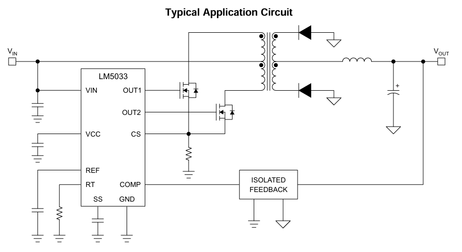
Typical Application
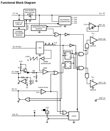
Block Diagram
Gerber View
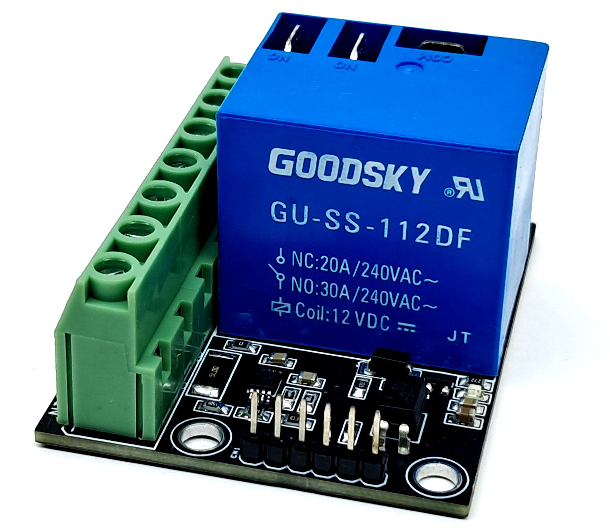
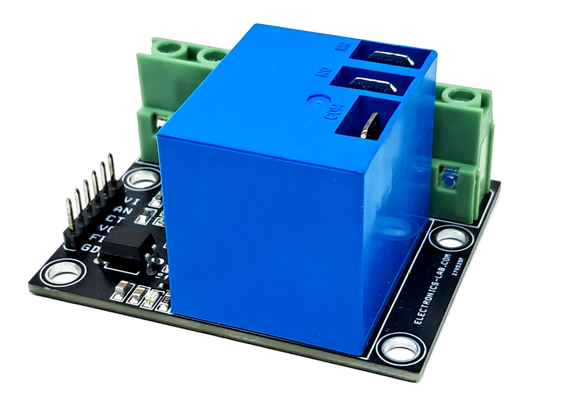
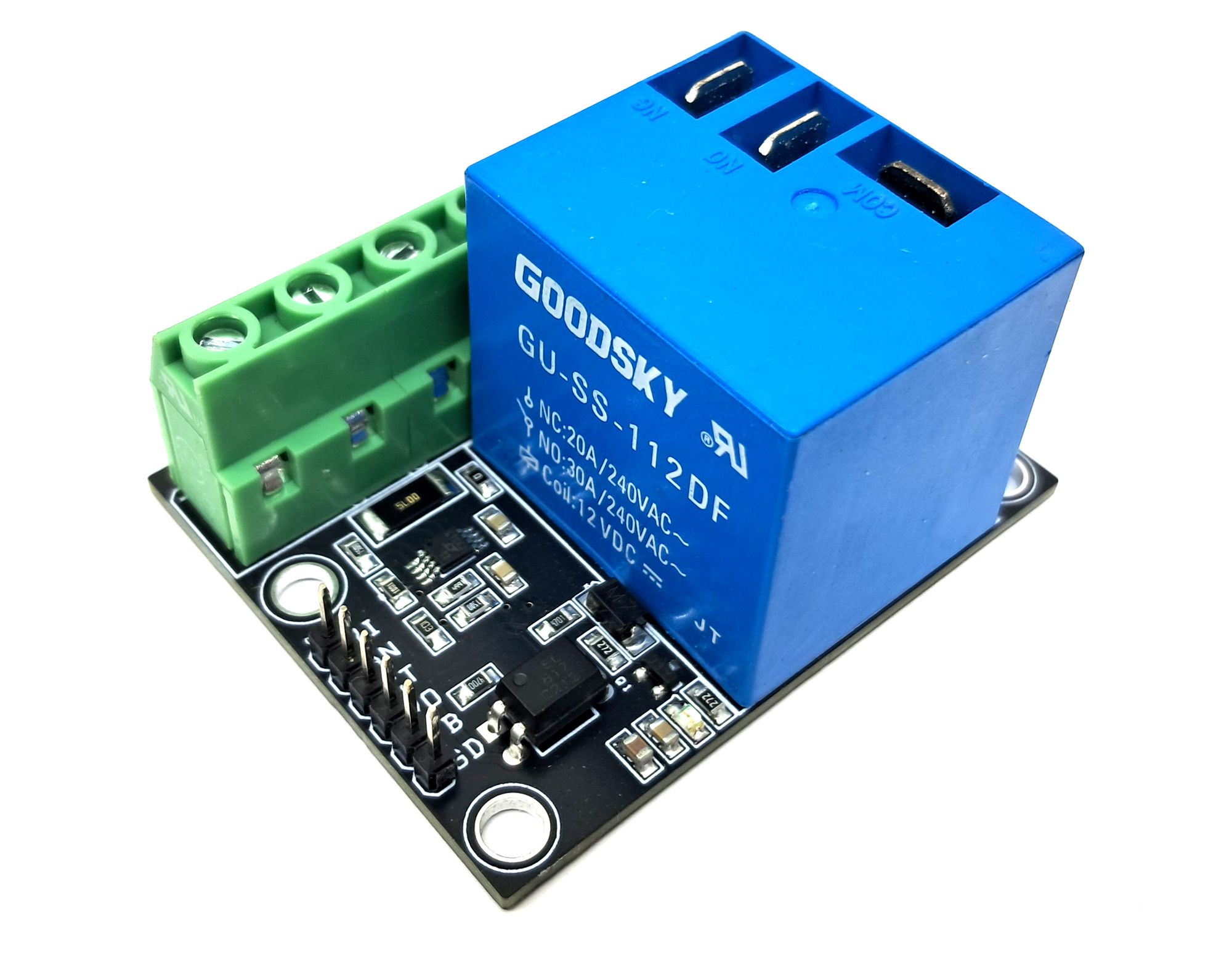
Photos