Under/Over Voltage and Current Protection Switch
This simple project allows users to design an under-voltage, over-voltage, under-current, and over-current protection switch. It is a highly useful system for safeguarding electrical loads against abnormal power or current conditions.

This simple project allows users to design an under-voltage, over-voltage, under-current, and over-current protection switch. It is a highly useful system for safeguarding electrical loads against abnormal power or current conditions.
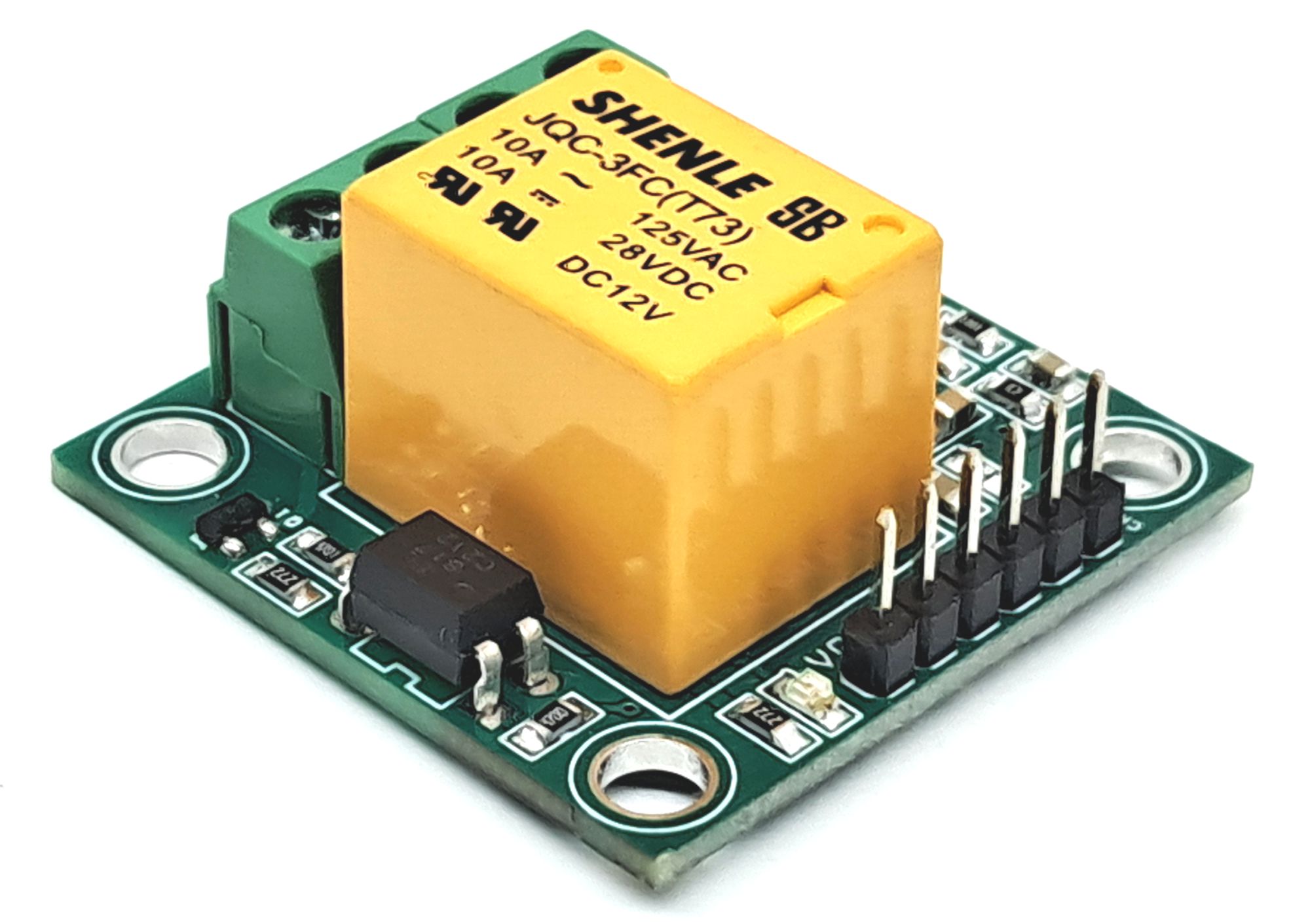
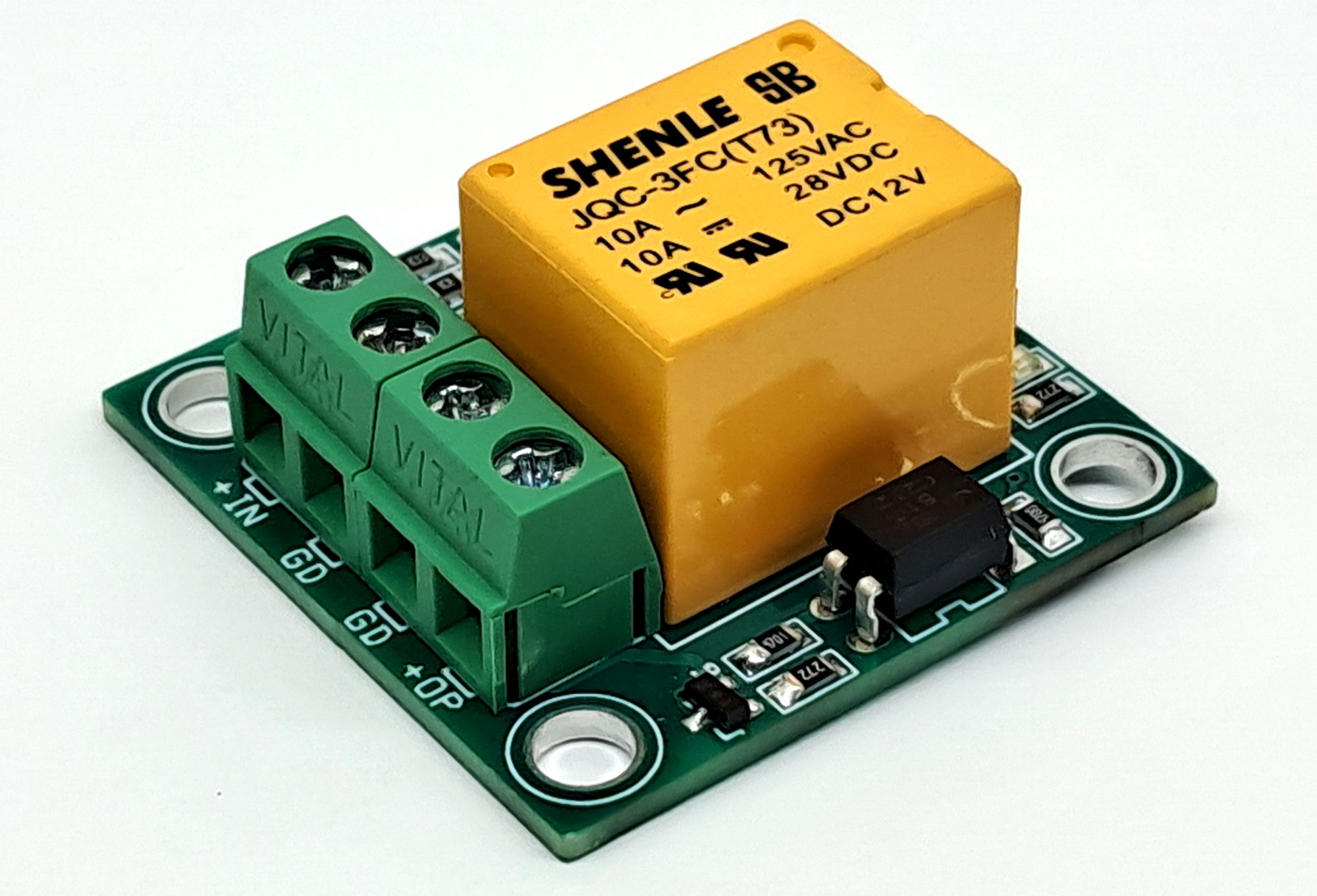
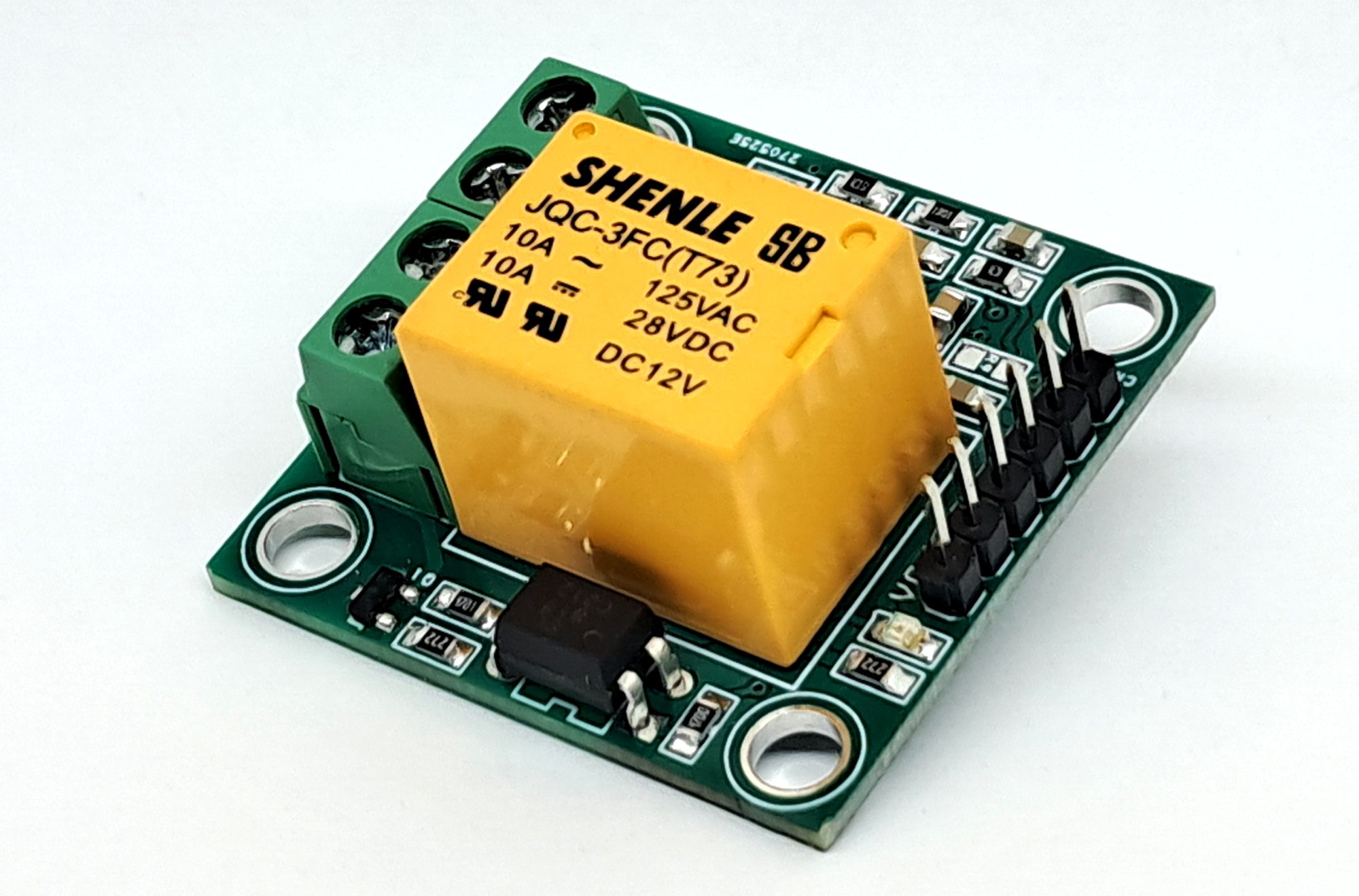
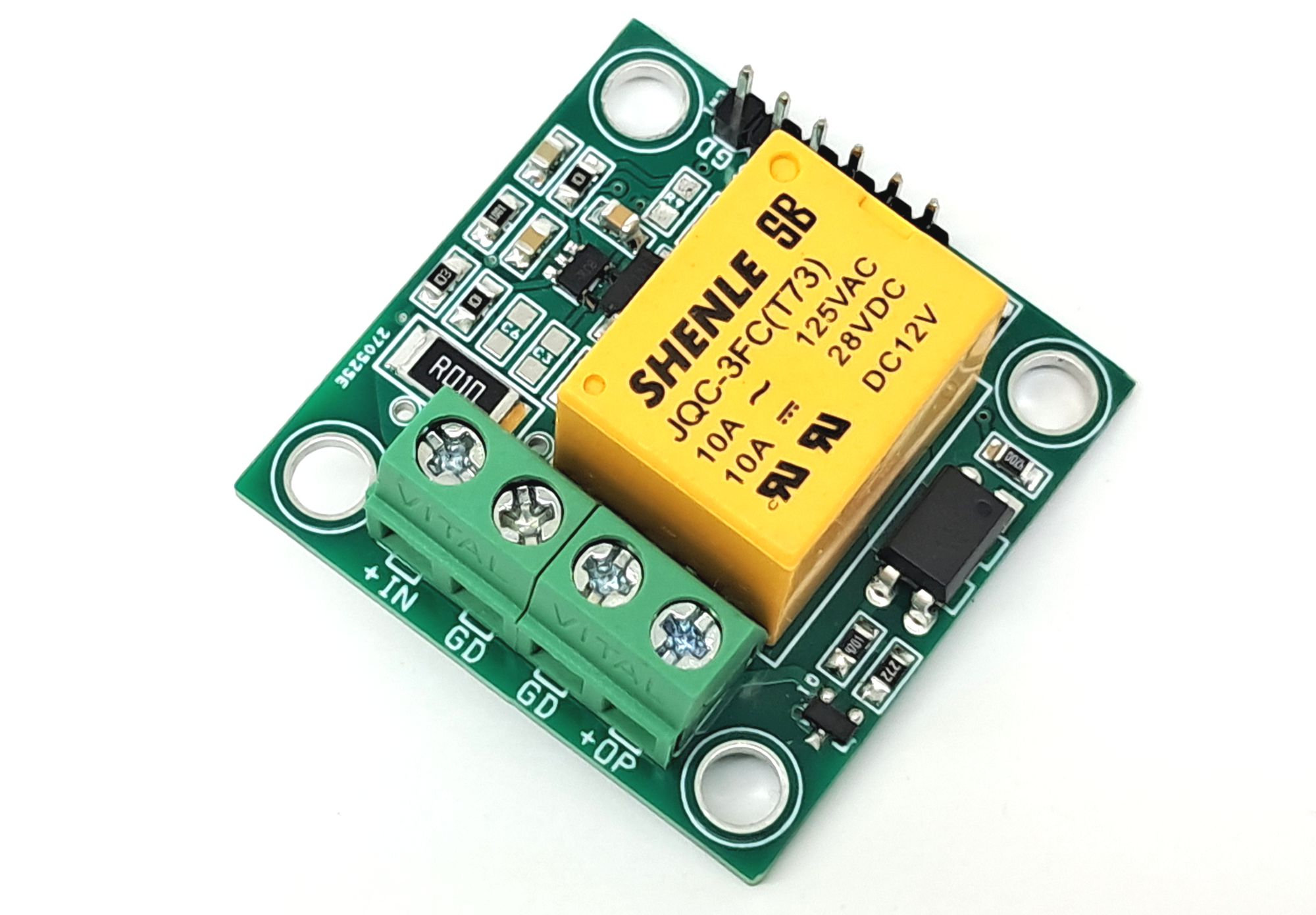
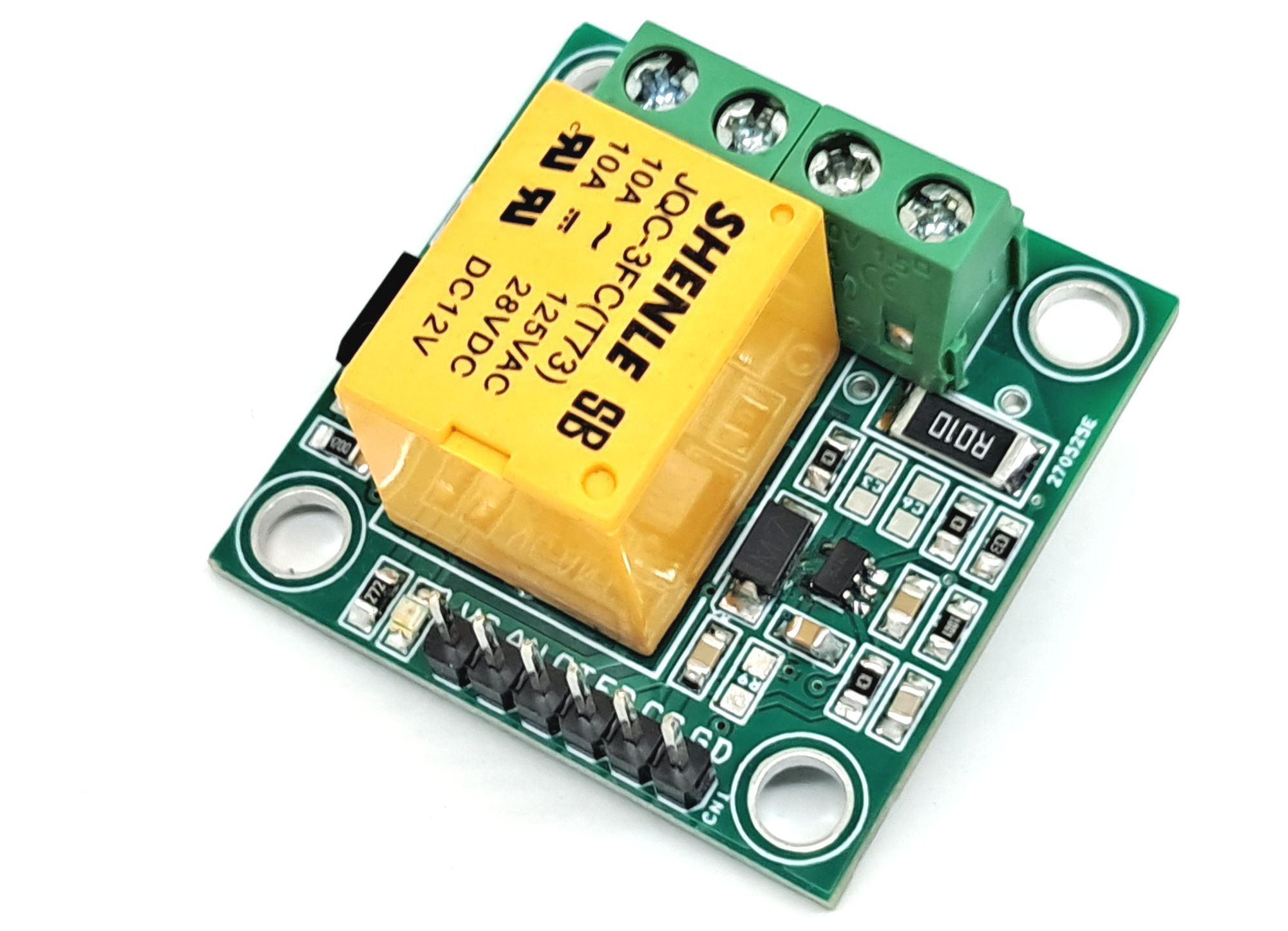
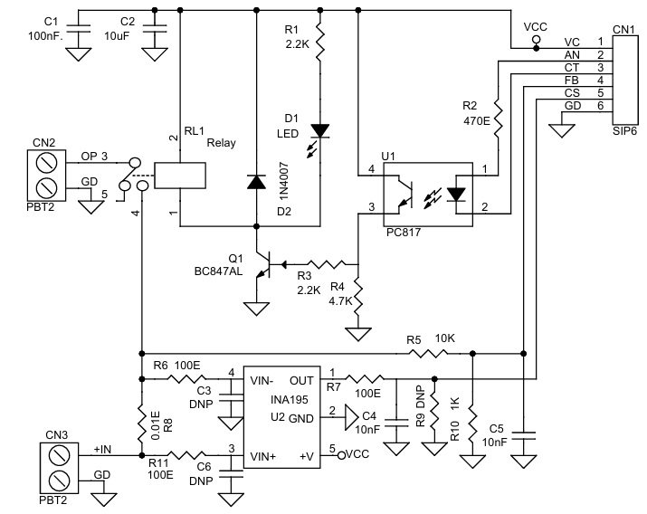
The project features a relay with optocoupler input, a current-sensing circuit based on the INA195 amplifier, a 10mΩ shunt resistor, and a voltage divider network for voltage feedback. It is primarily designed for low-voltage and low-current applications up to 4A, but the relay can handle loads up to 5 A at supply voltages up to 48 V.
The system can be easily controlled using an Arduino or other microcontroller. Voltage and current feedback signals are fed into the microcontroller’s ADC pins for measurement, while the relay can be switched using a 5 V control signal from the processor.
Over/Under Current Switch
The INA195 current-sense amplifier measures the voltage across the shunt resistor and provides an output voltage proportional to the load current. This output can be read by the microcontroller’s ADC to implement over-current or under-current protection logic.
The INA195 has a fixed gain of 100 V/V, providing an output of approximately 1 V per ampere of load current. For safety and relay handling limits, the recommended maximum current is below 5A. The system is designed for load voltages up to 48 V, ensuring that the ADC feedback voltage remains below 5 V.
Over/Under Voltage Switch
A resistor divider network, formed by R5 = 10 kΩ and R10 = 1 kΩ, is used to scale down the load voltage for ADC measurement. This feedback allows the controller to detect both over-voltage and under-voltage conditions. At 48 V input, the divider provides approximately 4.364 V, and at 5 V input, about 0.455V.
Features
- Supply 12V DC Relay and Current Sensor INA195
- Relay Trigger Input 5V 20mA
- Current Sensor Output 1V/A (5V at 5Amps)
- Load Up to 5Amps, Load Supply Up to 48V DC
- Load Power Supply Feedback 4.364 @ 48V, 0.455 @ 5V Supply
- 4 x 4 mm PCB Mounting Holes
- PCB Dimensions 35.56 x 35.40 mm
Arduino Control
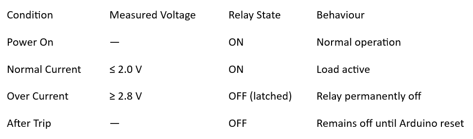
Sample Arduino code is provided to test the project. The code implements an over-current latch protection function, which can be easily modified for different threshold levels.
// ===== Overcurrent Latching Switch =====
// Relay ON at power-up
// Turns OFF (latches) when analog voltage exceeds 2.8V
// Stays OFF until reset

const int relayPin = 4;            // Relay output pin
const int currentSensorPin = A0;   // Analog input pin
const float tripVoltage = 2.8;     // Trip voltage (Volts)

bool relayLatchedOff = false;      // Latch state flag

void setup() {
  pinMode(relayPin, OUTPUT);
  digitalWrite(relayPin, HIGH);    // Relay ON at power-up
  Serial.begin(9600);
  Serial.println("Overcurrent Latch Protection Active...");
}

void loop() {
  int adcValue = analogRead(currentSensorPin);
  float voltage = (adcValue * 5.0) / 1023.0; // Assuming 5V reference

  Serial.print("Voltage: ");
  Serial.print(voltage, 3);
  Serial.print(" V | Relay: ");
  Serial.println(digitalRead(relayPin) ? "ON" : "OFF");

  // --- Overcurrent check ---
  if (!relayLatchedOff && voltage >= tripVoltage) {
    relayLatchedOff = true;       // Set latch
    digitalWrite(relayPin, LOW);  // Turn OFF relay
    Serial.println("⚠️ Overcurrent detected — relay latched OFF!");
  }

  // Once latched, relay stays off until reset
  delay(100); // Small delay for stable reading
}
Operating Logic Example
Connections
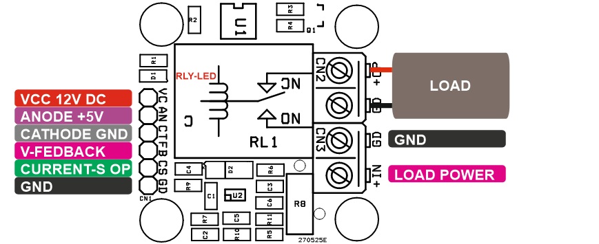
- CN1: Pin 1 = VCC/12V DC, Pin 2 = Optocoupler Anode +5V, Pin 3 = Optocoupler Cathode GND, Pin 4 = Bus Voltage Feedback, Pin 5 = Current Sensor Output, Pin 6 = GND
- CN2: Pin 1 = +Load Connection, Pin 2 = GND
- CN3: Pin 1 = +Load Supply Input, Pin 2 GND
- D1: Relay LED
Schematic
Parts List
| NO. | QNTY. | REF. | DESC. | MANUFACTURER | SUPPLIER | SUPPLIER PART NO |
|---|---|---|---|---|---|---|
| 1 | 1 | CN1 | 6 PIN MALE HEADER PITCH 2.54MM | WURTH | DIGIKEY | 732-5319-ND |
| 2 | 2 | CN2,CN3 | 2 PIN SCREW TERMINAL PITCH 5.08MM | PHOENIX | DIGIKEY | 277-1247-ND |
| 3 | 1 | C1 | 100nF/50V CERAMIC SMD SIZE 0805 | YAGEO/MURATA | DIGIKEY | |
| 4 | 1 | C2 | 10uF/25V CERAMIC SMD SIZE 0805 | YAGEO/MURATA | DIGIKEY | |
| 5 | 3 | C3,C6,R9 | DNP | |||
| 6 | 2 | C4,C5 | 10nF/50V CERAMIC SMD SIZE 0805 | YAGEO/MURATA | DIGIKEY | |
| 7 | 1 | D1 | LED RED SMD SIZE 0805 | OSRAM | DIGIKEY | 475-1278-1-ND |
| 8 | 1 | D2 | 1N4007 SMD | DIODE INCORPORATION | DIGIKEY | S1MBDITR-ND |
| 9 | 1 | Q1 | BC847AL SOT23 | NEXPERIA | DIGIKEY | 1727-2924-2-ND |
| 10 | 1 | RL1 | Relay SUGER CUBE 12V | TE | DIGIKEY | PB2029-ND |
| 11 | 2 | R1,R3 | 2.2K 5% SMD SIZE 0805 | YAGEO/MURATA | DIGIKEY | |
| 12 | 1 | R2 | 470E 5% SMD SIZE 0805 | YAGEO/MURATA | DIGIKEY | |
| 13 | 1 | R4 | 4.7K 5% SMD SIZE 0805 | YAGEO/MURATA | DIGIKEY | |
| 14 | 1 | R5 | 10K 5% SMD SIZE 0805 | YAGEO/MURATA | DIGIKEY | |
| 15 | 3 | R6,R7,R11 | 100E 5% SMD SIZE 0805 | YAGEO/MURATA | DIGIKEY | |
| 16 | 1 | R8 | 0.01E/2W 1% SMD SIZE 2512 | BOURNS INC | DIGIKEY | CRF2512-FZ-R010ELFCT-ND |
| 17 | 1 | R10 | 1K 5% SMD SIZE 0805 | YAGEO/MURATA | DIGIKEY | |
| 18 | 1 | U1 | PC817 DIP4 PIN | SHARP | DIGIKEY | PC817X2NSZ9F-ND |
| 19 | 1 | U2 | INA195 SOT23-5 | TI | DIGIKEY | 296-26067-1-ND |
Connections
Gerber View
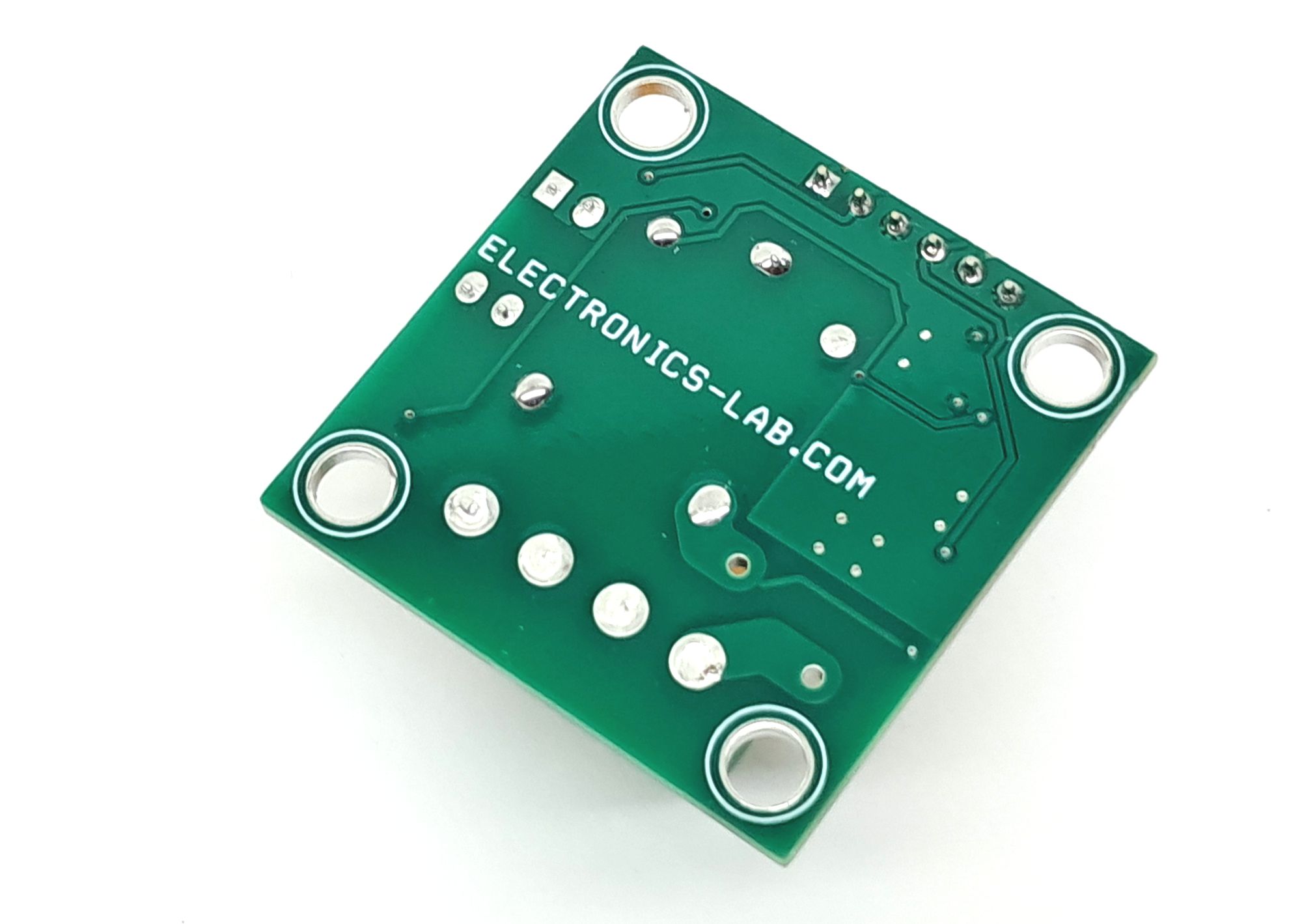
Photos