Voltage Controlled Oscillator with Isolated Output
Precision Oscillator: 1–31kHz programmable range. Compact board acts as fixed-frequency or VCO.
This compact project is a precision oscillator with a programmable frequency range from 1 kHz to 31 kHz. The board can be used as either a fixed-frequency oscillator or a voltage-controlled oscillator (VCO).
- For fixed-frequency operation, use the RSET resistor R7. (Refer data sheet of LT6990 for more Info)
- For adjustable frequency, install the trimmer potentiometer PR1.
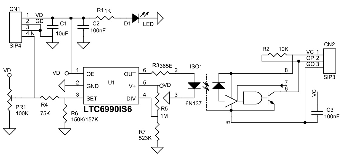
A high-speed optocoupler (6N137) is used to provide an isolated output. The resistor R7 (RSET) programs the LTC6990’s internal master oscillator frequency. The final output frequency is determined by this master oscillator along with an internal frequency divider (NDIV), which is programmable to eight settings ranging from 1 to 128. Resistors R5 and R7 may be modified to alter the master oscillator frequency. Frequency can also be controlled using an external voltage input at CN1 pin 4. In this mode, do not install the trimmer potentiometer PR1. The LTC6990 includes an enable function synchronized with the master oscillator, ensuring clean and glitch-free output pulses. Enable is default connected to VD. The high-speed optocoupler 6N137 provides isolation between the oscillator and the output, allowing this module to interface safely with high-voltage circuits.
Features
- Supply VDD 5V DC Input Side (VD)
- Supply VCC 5V-12V Output Side of Optocoupler (VC)
- Fixed-Frequency or Voltage-Controlled Operation
- Optically Isolated Output
- Fixed: Single Resistor Programs Frequency with <1.5% Max Error
- VCO: Two Resistors Set VCO Centre Frequency and Tuning Range
- Frequency Range: Default 1Khz to 31Khz (Range 488Hz to 2MHz)
- 72µA Supply Current at 100kHz (DS6990)
- 500µs Start-Up Time
- VCO Bandwidth >300kHz at 1MHz
- CMOS Logic Output Sources/Sinks 20mA (DS6990)
- 50% Duty Cycle Square Wave Output
- PCB Dimensions 29.69 x 15.72 mm
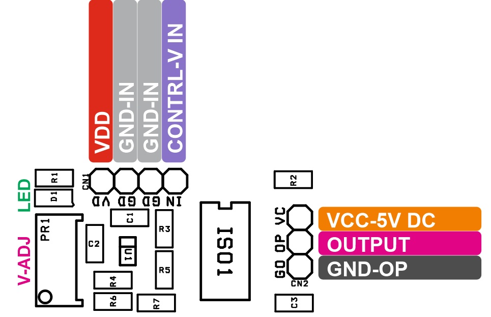
Connections
- CN1: Pin 1 = VDD, Pin 2 = GND, Pin 3 = GND, Pin 4 = Control Voltage Input (Optional)
- CN2: Pin 1 = VCC, Pin 2 = Output, Pin 3 = GND-Output
- D1: Power LED
- PR1: Frequency Adjust Trimmer Pot
Schematic
Parts List
| BOM | ||||||
|---|---|---|---|---|---|---|
| NO. | QNTY. | REF. | DESC. | MANUFACTURER | SUPPLIER | SUPPLIER PART NO |
| 1 | 1 | CN1 | 4 PIN MALE HEADER PITCH 2.54MM | WURTH | DIGIKEY | 732-5317-ND |
| 2 | 1 | CN2 | 3 PIN MALE HEADER PITCH 2.54MM | WURTH | DIGIKEY | 732-5316-ND |
| 3 | 1 | C1 | 10uF/16V CERAMIC SMD SIZE 0805 | YAGEO/MURATA | DIGIKEY | |
| 4 | 2 | C2,C3 | 100nF/50V CERAMIC SMD SIZE 0805 | YAGEO/MURATA | DIGIKEY | |
| 5 | 1 | D1 | LED RED SMD SIZE 0805 | OSRAM | DIGIKEY | 475-1278-1-ND |
| 6 | 1 | ISO1 | 6N137 DIP8 | LITE ON INC | DIGIKEY | 160-1791-ND |
| 7 | 1 | PR1 | 100K TRIMMER POT | BOURNS INC | DIGIKEY | 3296W-104LF-ND |
| 8 | 1 | R1 | 1K 5% SMD SIZE 0805 | YAGEO/MURATA | DIGIKEY | |
| 9 | 1 | R2 | 10K 5% SMD SIZE 0805 | YAGEO/MURATA | DIGIKEY | |
| 10 | 1 | R3 | 365E 1% SMD SIZE 0805 | YAGEO/MURATA | DIGIKEY | |
| 11 | 1 | R4 | 75K 1% SMD SIZE 0805 | YAGEO/MURATA | DIGIKEY | |
| 12 | 1 | R5 | 1M 1% SMD SIZE 0805 | YAGEO/MURATA | DIGIKEY | |
| 13 | 1 | R6 | 150K 1% SMD SIZE 0805 | YAGEO/MURATA | DIGIKEY | |
| 14 | 1 | R7 | 523K 1% SMD SIZE 0805 | YAGEO/MURATA | DIGIKEY | |
Connections
Gerber View
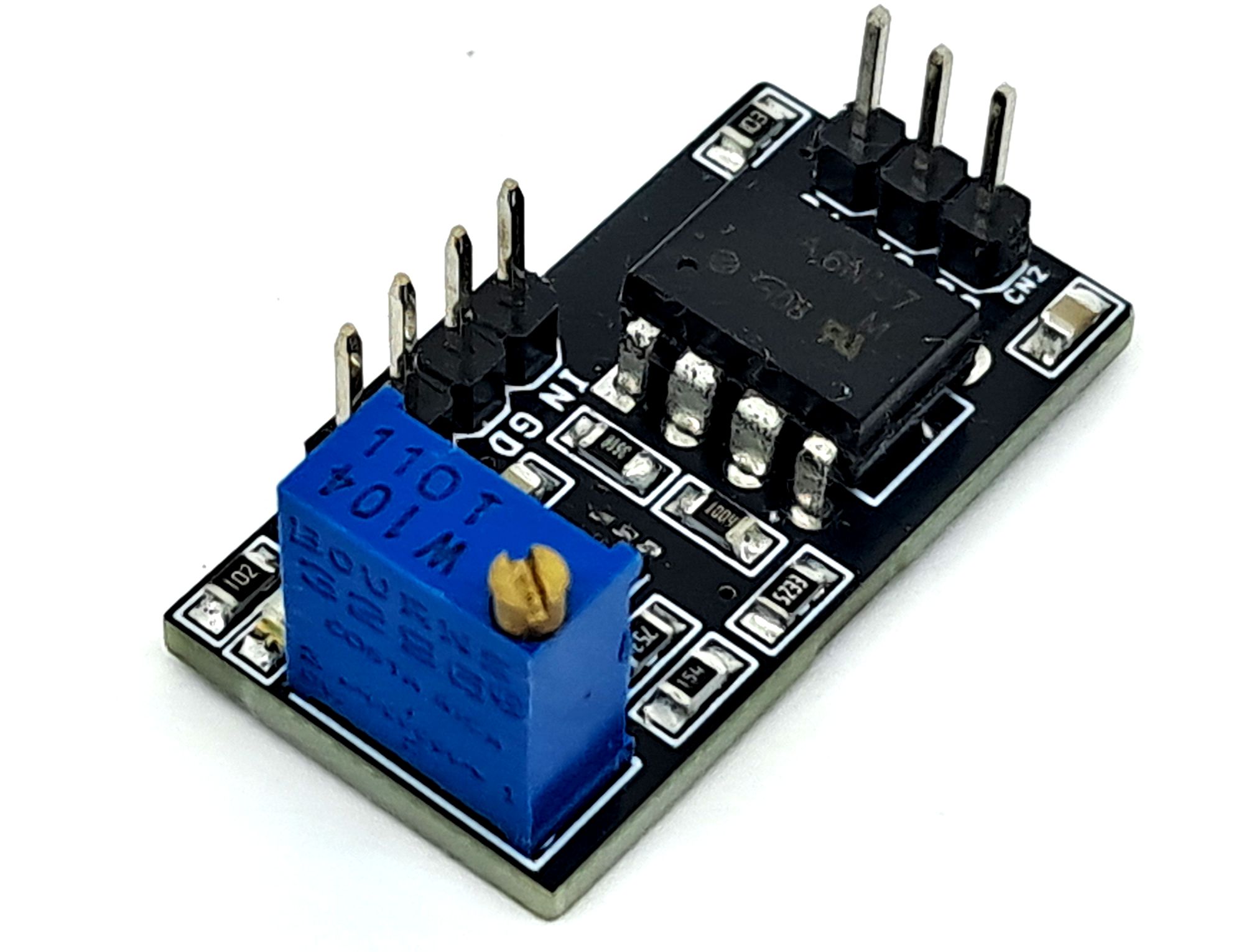
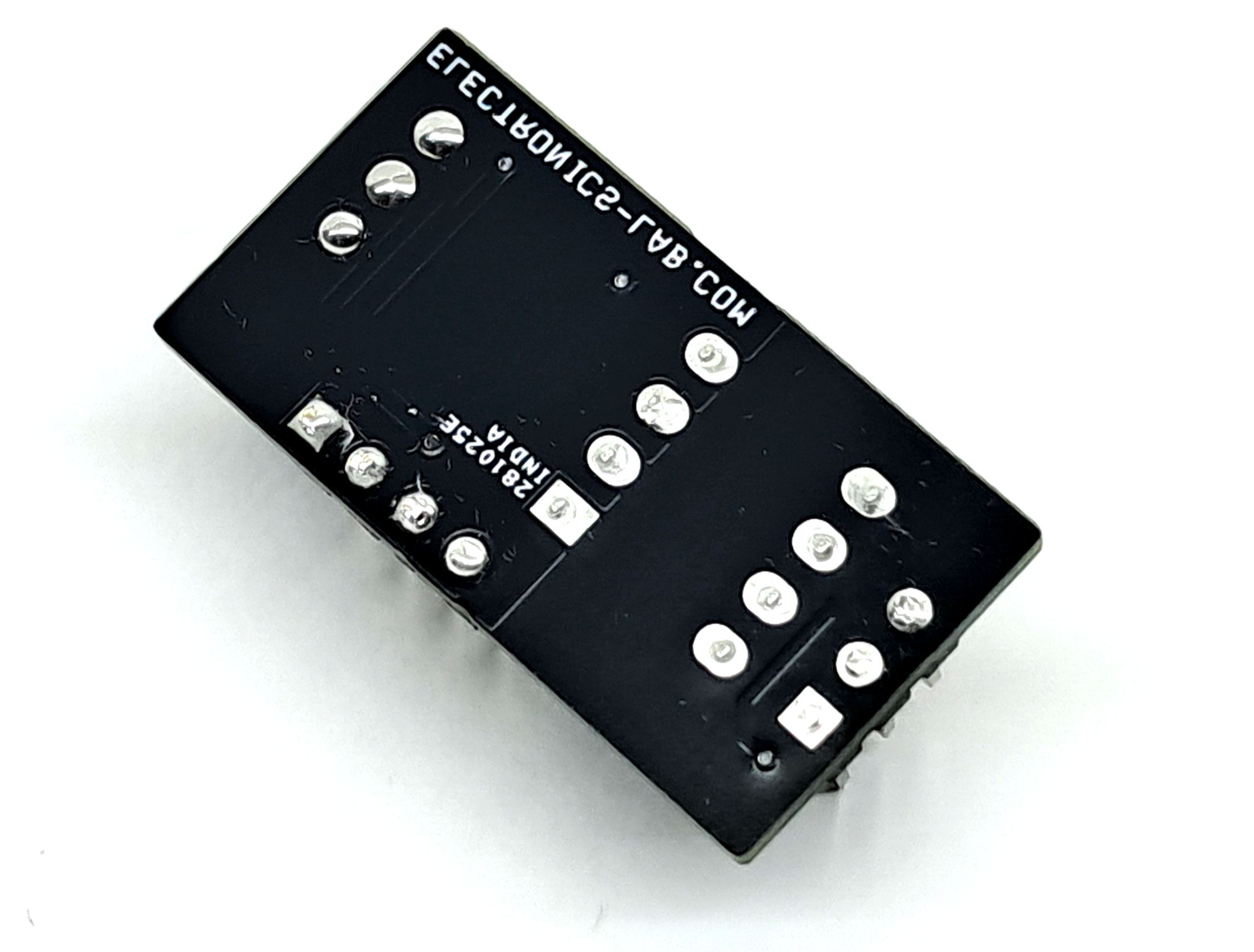
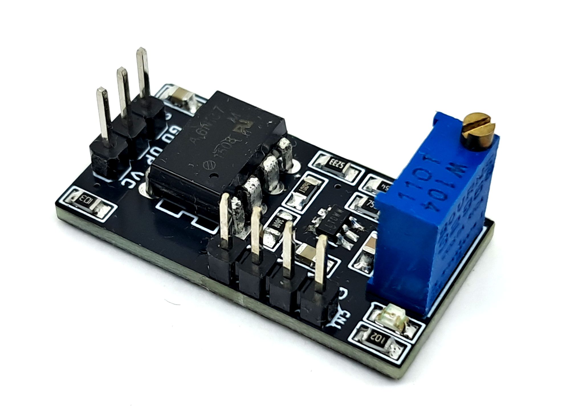
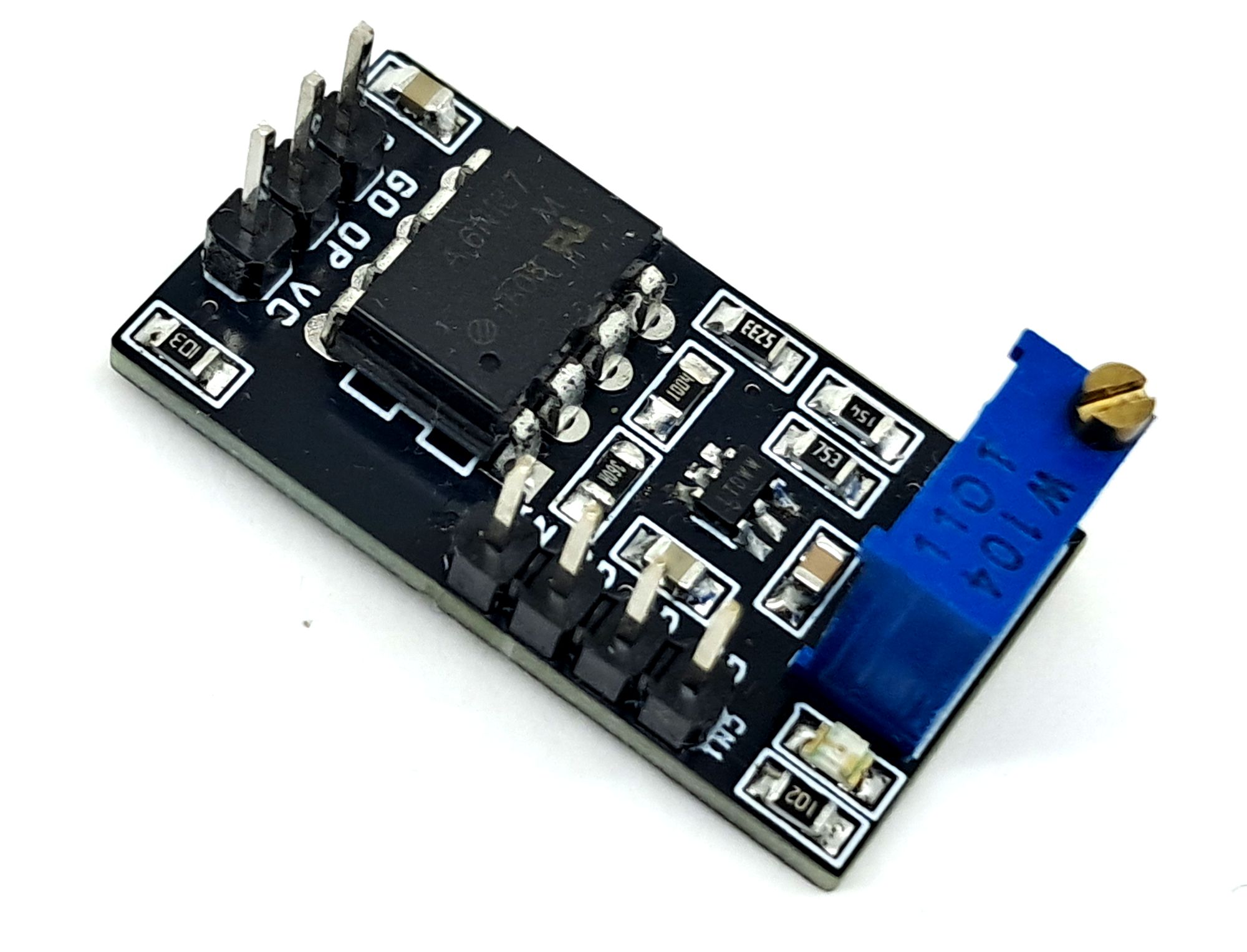
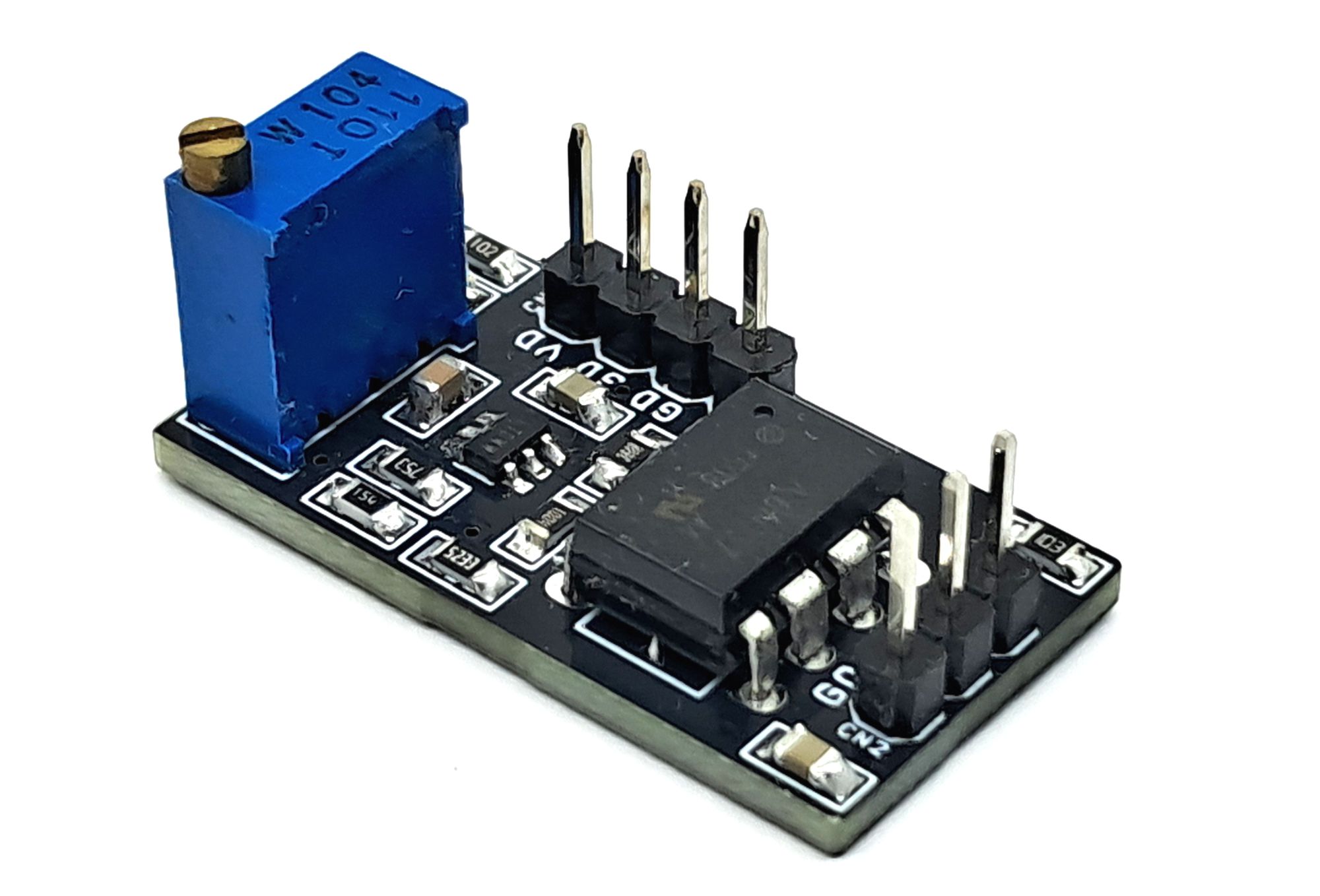
Photos