3W Switch Mode Power Supply – 12V output
The project presented here is 3W Switch mode power supply mainly designed for LED applications. The project is based on LNK364 chip from Power Integrations.
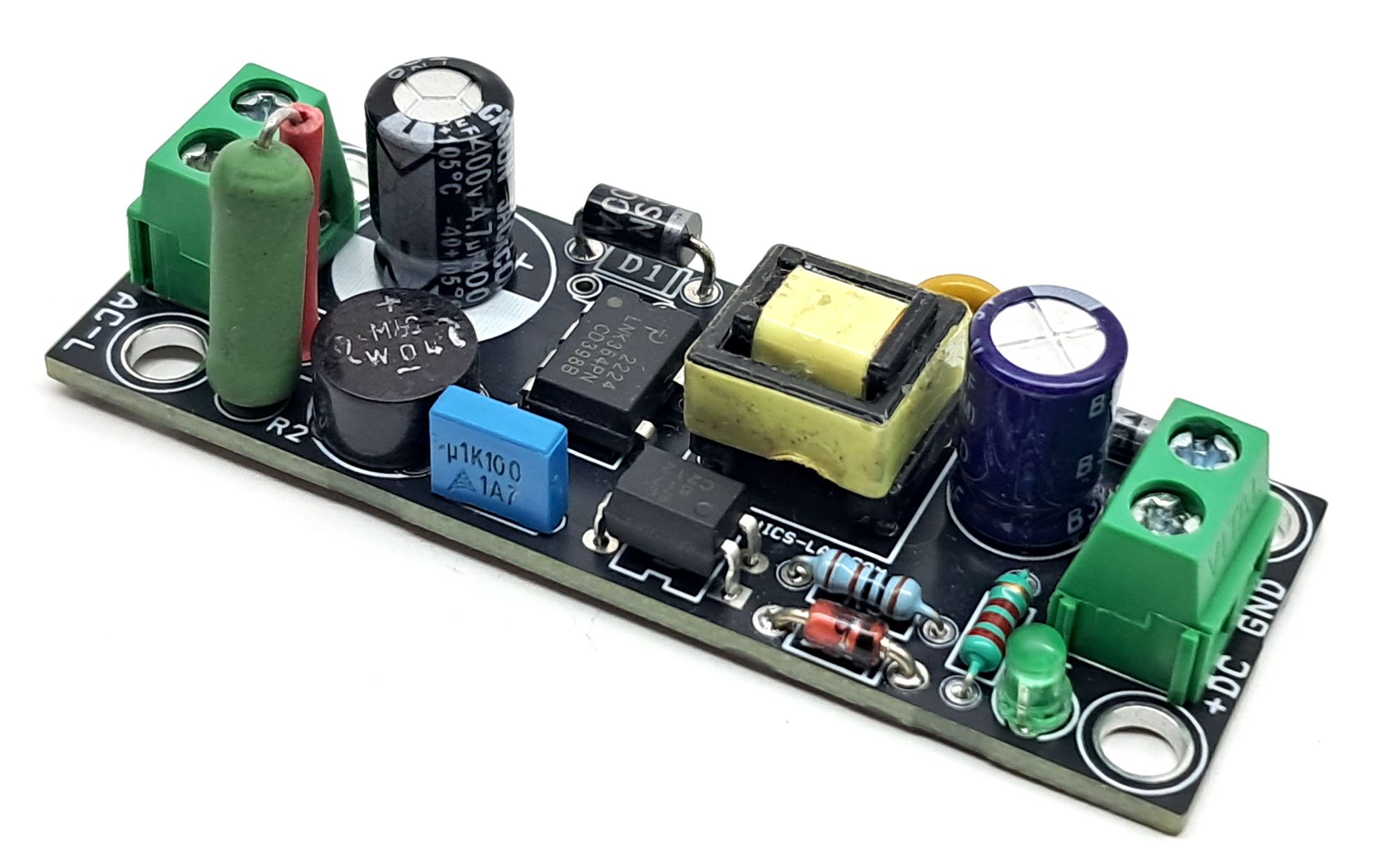
The project presented here is 3W Switch mode power supply mainly designed for LED applications. The project is based on LNK364 chip from Power Integrations. LNK364 incorporates a 700V power MOSFET, oscillator, simple ON/OFF control scheme, a high-voltage switched current source, frequency jittering, cycle-bicycle current limit and thermal shutdown circuitry onto a monolithic IC. The start-up and operating power are derived directly from the DRAIN pin, eliminating the need for a bias winding and associated circuitry.
Features
- Power Input 85-265 VAC
- Output 12V DC
- Output Current 250mA
- Operating Frequency 132Khz
- Short Circuit Protection
- Low Profile Compact Design
- Screw Terminals for Power Input and Output
- On Board Output LED
- PCB Dimensions 67.31 x 24.29 mm
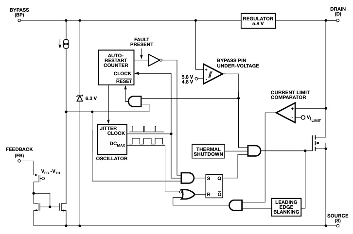
LNK364 Functional Description
LinkSwitch-XT combines a high-voltage power MOSFET switch with a power supply controller in one device. Unlike conventional PWM (pulse width modulator) controllers, a simple ON/OFF control regulates the output voltage. The controller consists of an oscillator, feedback (sense and logic) circuit, 5.8 V regulator, BYPASS pin undervoltage circuit, over-temperature protection, frequency jittering, current limit circuit, and leading-edge blanking integrated with a 700 V power MOSFET. The LinkSwitch-XT incorporates additional circuitry for auto-restart.
Oscillator
The typical oscillator frequency is internally set to an average of 132 kHz. Two signals are generated from the oscillator: the maximum duty cycle signal (DCMAX) and the clock signal that indicates the beginning of each cycle.
Feedback Input Circuit
The feedback input circuit at the FB pin consists of a low impedance source follower output set at 1.63 V for LNK364. When the current delivered into this pin exceeds 49 µA, a low logic level (disable) is generated at the output of the feedback circuit. This output is sampled at the beginning of each cycle on the rising edge of the clock signal. If high, the power MOSFET is turned on for that cycle (enabled), otherwise the power MOSFET remains off (disabled). Since the sampling is done only at the beginning of each cycle, subsequent changes in the FB pin voltage or current during the remainder of the cycle are ignored.
Auto-Restart
In the event of a fault condition such as output overload, output short-circuit, or an open loop condition, LinkSwitch-XT enters into auto-restart operation. An internal counter clocked by the oscillator gets reset every time the FB pin is pulled high. If the FB pin is not pulled high for approximately 40 ms, the power MOSFET switching is disabled for 800 ms. The auto-restart alternately enables and disables the switching of the power MOSFET until the fault condition is removed.
Current Limit
The current limit circuit senses the current in the power MOSFET. When this current exceeds the internal threshold (ILIMIT), the power MOSFET is turned off for the remainder of that cycle. The leading-edge blanking circuit inhibits the current limit comparator for a short time (tLEB ) after the power MOSFET is turned on. This leading-edge blanking time has been set so that current spikes caused by capacitance and rectifier reverse recovery time will not cause premature termination of the switching pulse.
Over-Temperature Protection
The thermal shutdown circuitry senses the die temperature. The threshold is set at 142 °C typical with a 75 °C hysteresis. When the die temperature rises above this threshold (142 °C) the power MOSFET is disabled and remains disabled until the die temperature falls by 75 °C, at which point it is re-enabled.
BYPASS Pin Undervoltage
The BYPASS pin undervoltage circuitry disables the power MOSFET when the BYPASS pin voltage drops below 4.8 V. Once the BYPASS pin voltage drops below 4.8 V, it must rise back to 5.8 V to enable (turn-on) the power MOSFET.
Transformer
Transformer can be source from AliExpress and eBay, Transformer made with EE10 Magnet Core, primary inductance of transformer is 2.6-4mH. Turn ratio 145:18.
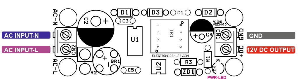
Connections
- CN1: Pin 1 = 12V DC Output, Pin 2 = GND
- CN2: Pin 1 = AC-Neutral, Pin 2 = AC Live
- D4: Power LED
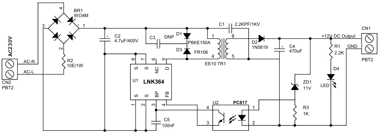
Schematic
 Parts List
| NO. | QNTY. | REF. | DESC. | MANUFACTURER | SUPPLIER | SUPPLIER PART NO |
|---|---|---|---|---|---|---|
| 1 | 1 | BR1 | WO4M BRIDGE RECTIFIER 400V/1A | LUMIMEX OPTO | 4491-W04M-ND | |
| 2 | 2 | CN1,CN2 | 2PIN SCREW TERMINAL PITCH 2.54MM | PHOENIX | 277-1247-ND | |
| 3 | 1 | C1 | 2.2KPF/1KV | TDK | 445-CK45-B3AD472KYVNATR-ND | |
| 4 | 1 | C2 | 4.7uF/400V | NICHICON | 493-13004-1-ND | |
| 5 | 1 | C3 | DNP | |||
| 6 | 1 | C4 | 470uF/16V | RUBYCON | 1189-1549-1-ND | |
| 7 | 1 | C5 | 100nF/63V 5MM THT | |||
| 8 | 1 | D1 | P6KE150A | ST | 497-11384-3-ND | |
| 9 | 1 | D2 | 1N5819 | ST | 497-6610-1-ND | |
| 10 | 1 | D3 | FR106 | SMC | 1655-FR106TB-ND | |
| 11 | 1 | D4 | LED 3MM ROUND GREEN | WURTH | 732-5008-ND | |
| 12 | 1 | R1 | 2.2K 5% 1/4W THT | YAGEO | ||
| 13 | 1 | R2 | 10E/1W 5% THT | YAGEO | 13-CFR1WSJT-52-10RCT-ND | |
| 14 | 1 | R3 | 1K 5% 1/4W THT | YAGEO | ||
| 15 | 1 | TR1 | EE10 TRANSFORMER | CHIN/ALIEXPRESS | ||
| 16 | 1 | U1 | LINK364 | POWER INTERGRATIION | 596-1088-5-ND | |
| 17 | 1 | U2 | PC817 | SHARP | PC817X2NSZ9F-ND | |
| 18 | 1 | ZD1 | 11V ZENER 1N4741A-ND | ONSEMI | 1N4741A-ND |
Connections
Application Schematic
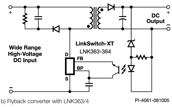
Block Diagram
Transformer Dimensions
![]()
![]()
Gerber View
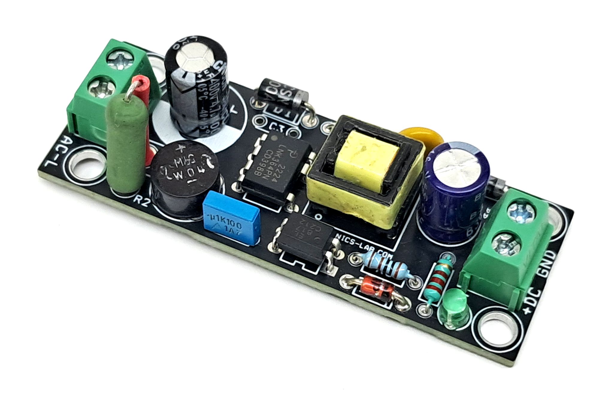
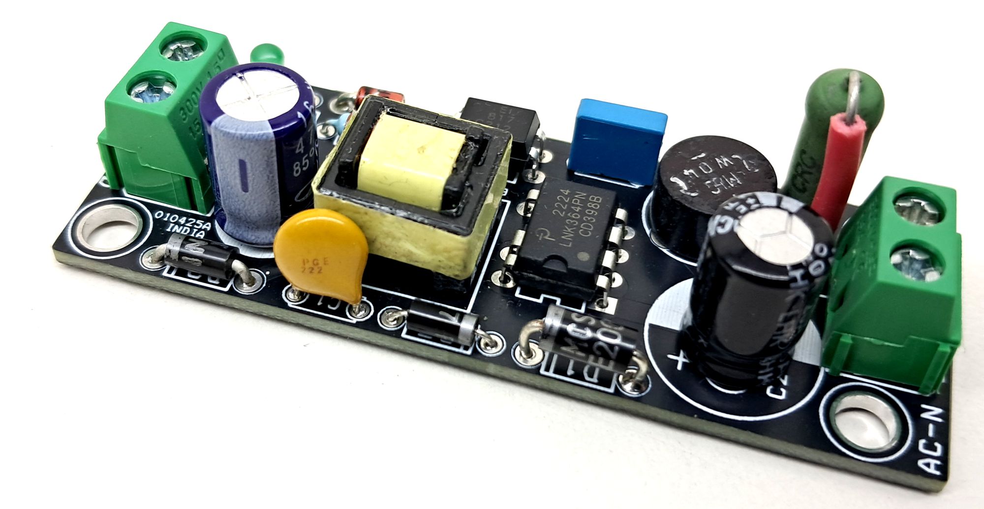
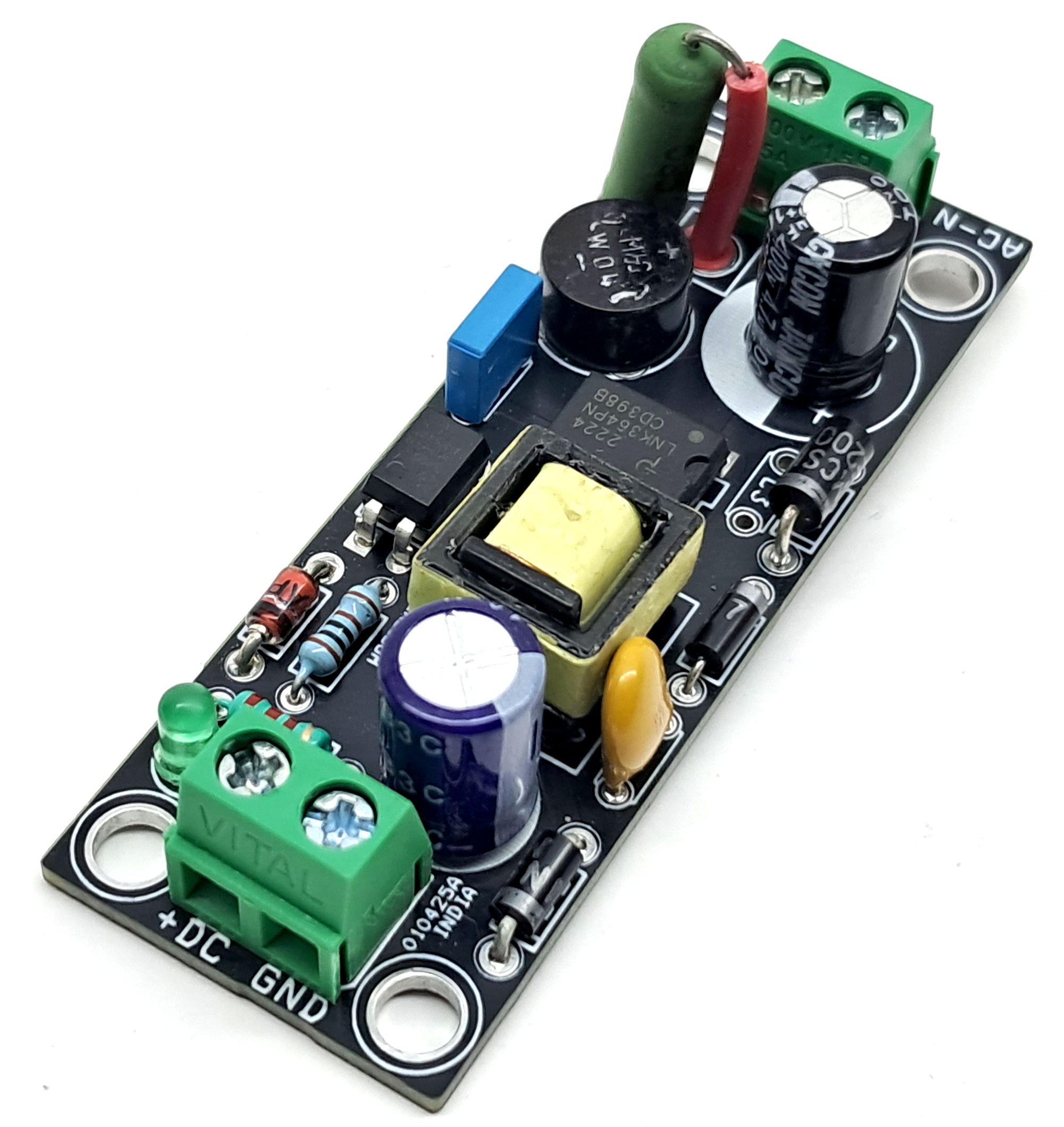
Photos

C1 should be a safety class y1 capacitor
Is r2 fusible?..
No interference filter???