60V to 5V @ 3.5A Buck converter with USB output
This is a 60V to 5V - 3.5A step down DC-DC converter based on TPS54360B from Texas Instruments. Sample applications are: 12 V, 24 V and 48 V industrial, Automotive and Communications Power Systems.
This is a 60V to 5V – 3.5A step down DC-DC converter based on TPS54360B from Texas Instruments. Sample applications are: 12 V, 24 V and 48 V industrial, Automotive and Communications Power Systems. The TPS54360 is a 60V, 3.5A, step down regulator with an integrated high side MOSFET. The device survives load dump pulses up to 65V per ISO 7637. Current mode control provides simple external compensation and flexible component selection. A low ripple pulse skip mode reduces the no load supply current to 146 μA. Shutdown supply current is reduced to 2 μA when the enable pin is pulled low.
Under-voltage lockout is internally set at 4.3 V but can be increased using the enable pin. The output voltage start up ramp is internally controlled to provide a controlled start up and eliminate overshoot. A wide switching frequency range allows either efficiency or external component size to be optimized. Frequency fold back and thermal shutdown protects internal and external components during an overload condition.
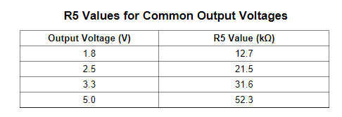
Note: The output voltage is set by a resistor divider from the output node to the FB terminal. It is recommended to use 1% tolerance or better divider resistors, choose R5, R6 for other output voltages.
Setting Output Voltage
The following table lists the R5 values for some common output voltages assuming R6= 10.0kΩ
Features
- Supply Input 8.5V-60V
- Output 5V (Output Voltage adjustable with R5, R6)
- Output Current 3.5A
- 100 kHz to 2.5 MHz Switching Frequency
- Optional JST connector for 5V Fan
- Current Mode Control DC-DC Converter
- Integrated 90-mΩ High Side N-Channel MOSFET
- High Efficiency at Light Loads with Pulse Skipping Eco-mode™
- Low Dropout at Light Loads with Integrated BOOT Recharge FET
- 146 μA Operating Quiescent Current
- 1 µA Shutdown Current
- Internal Soft-Start
- Accurate Cycle-by-Cycle Current Limit
- Thermal, Overvoltage, and Frequency Fold back Protection
- PCB Dimensions 55.50mm x 24.64mm
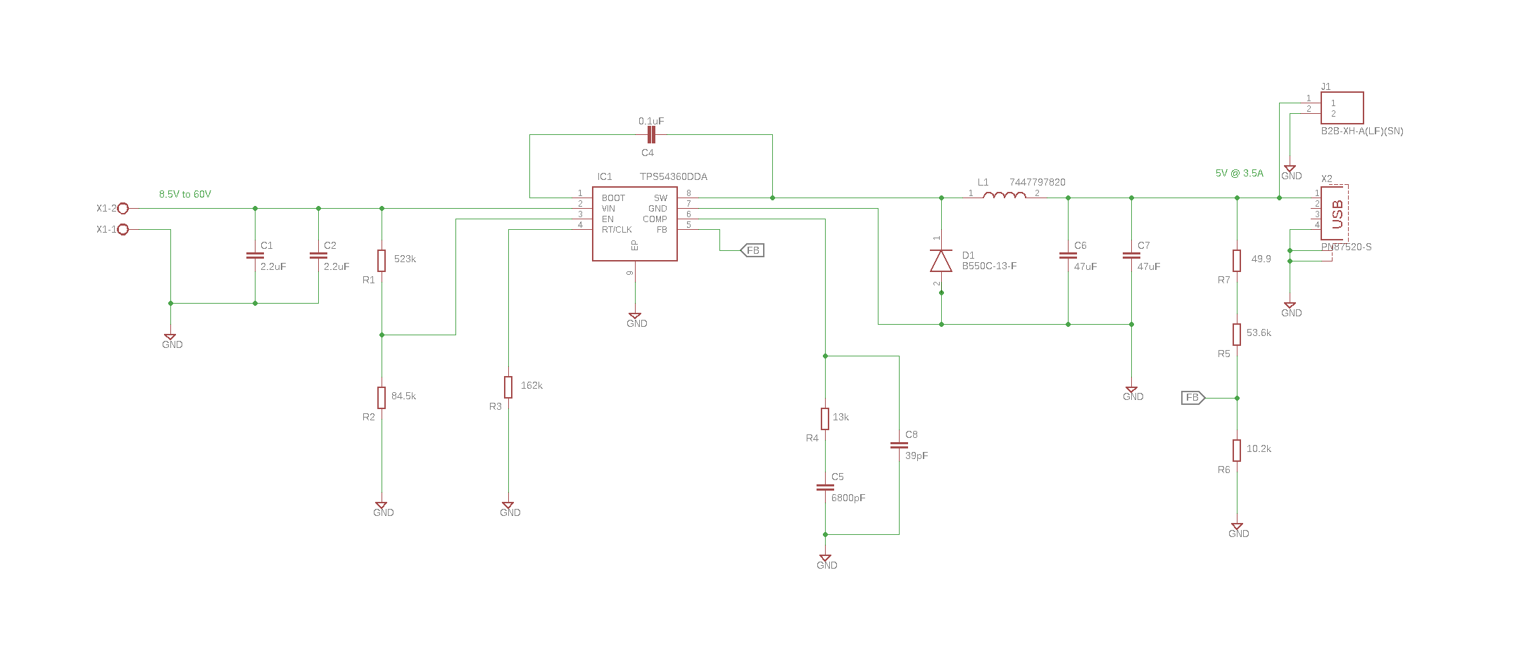
Schematic
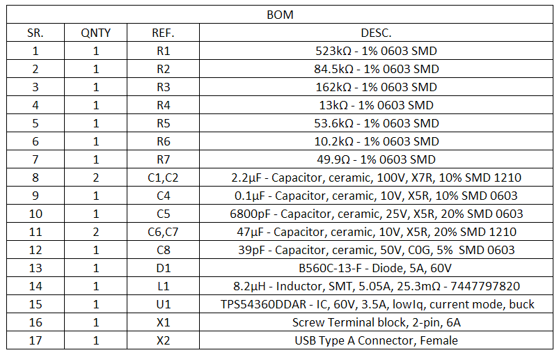
Parts List
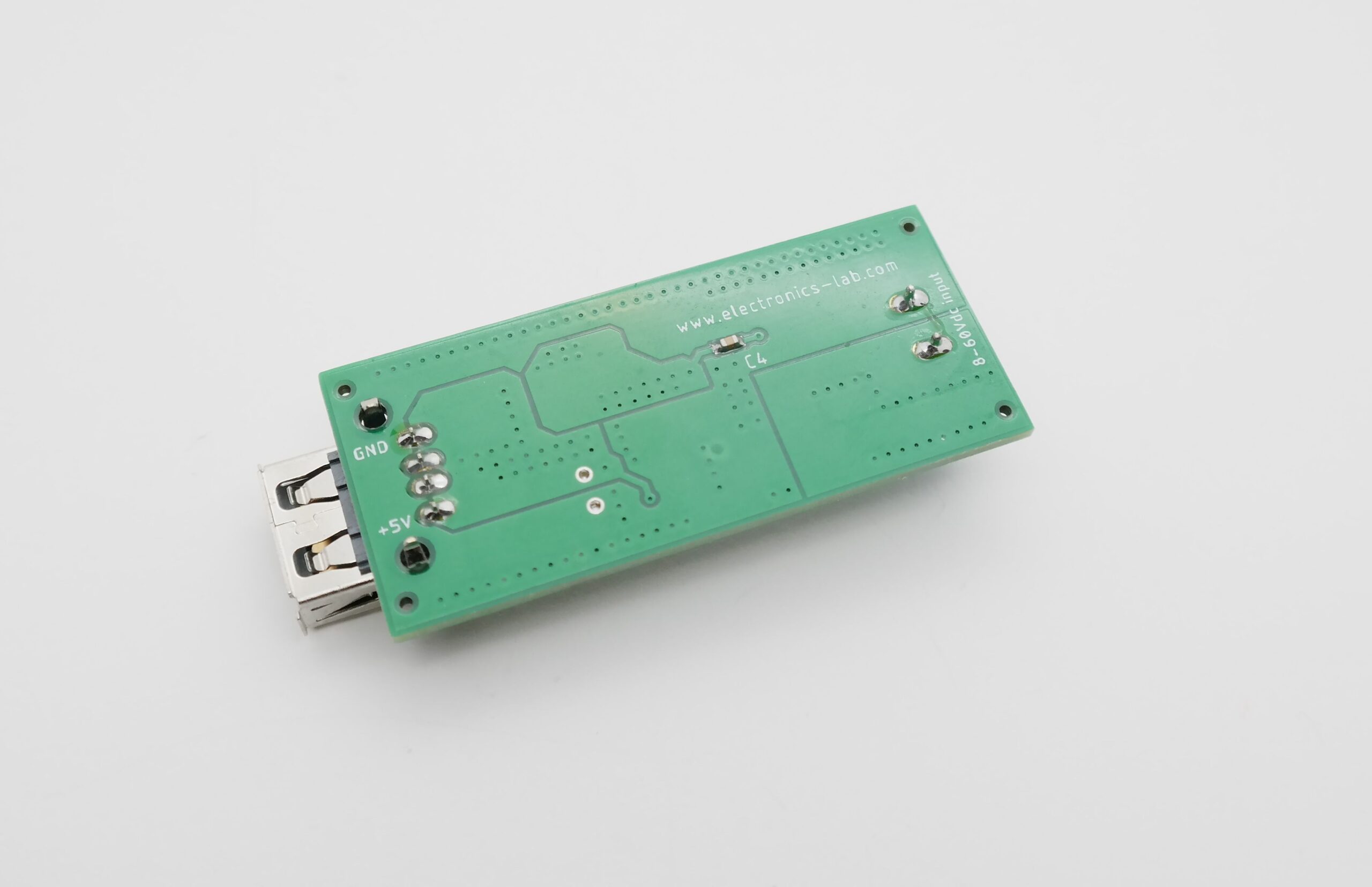
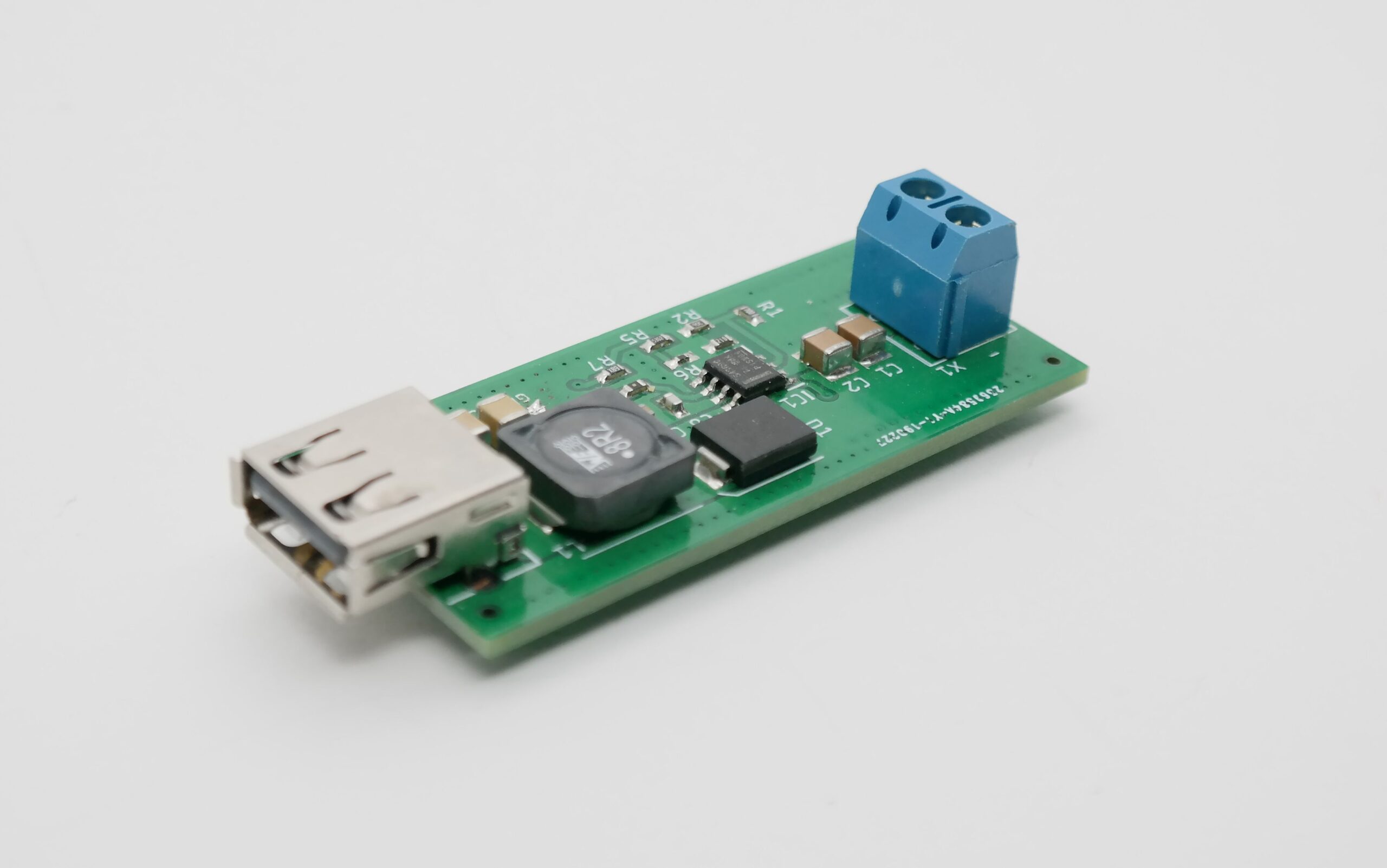
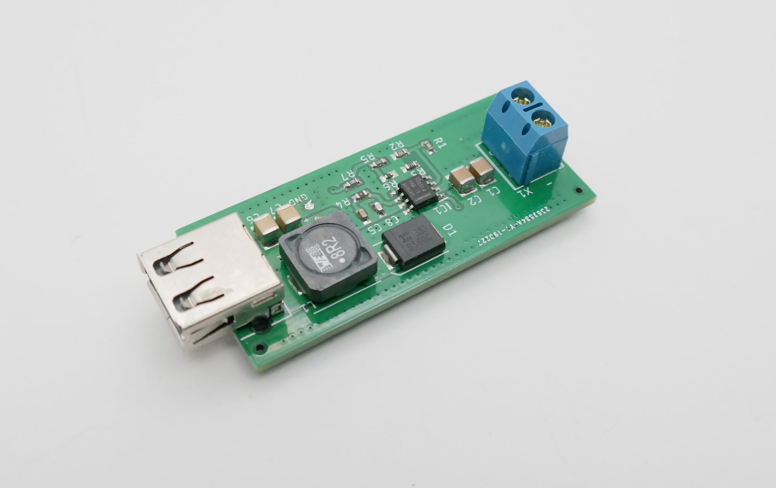
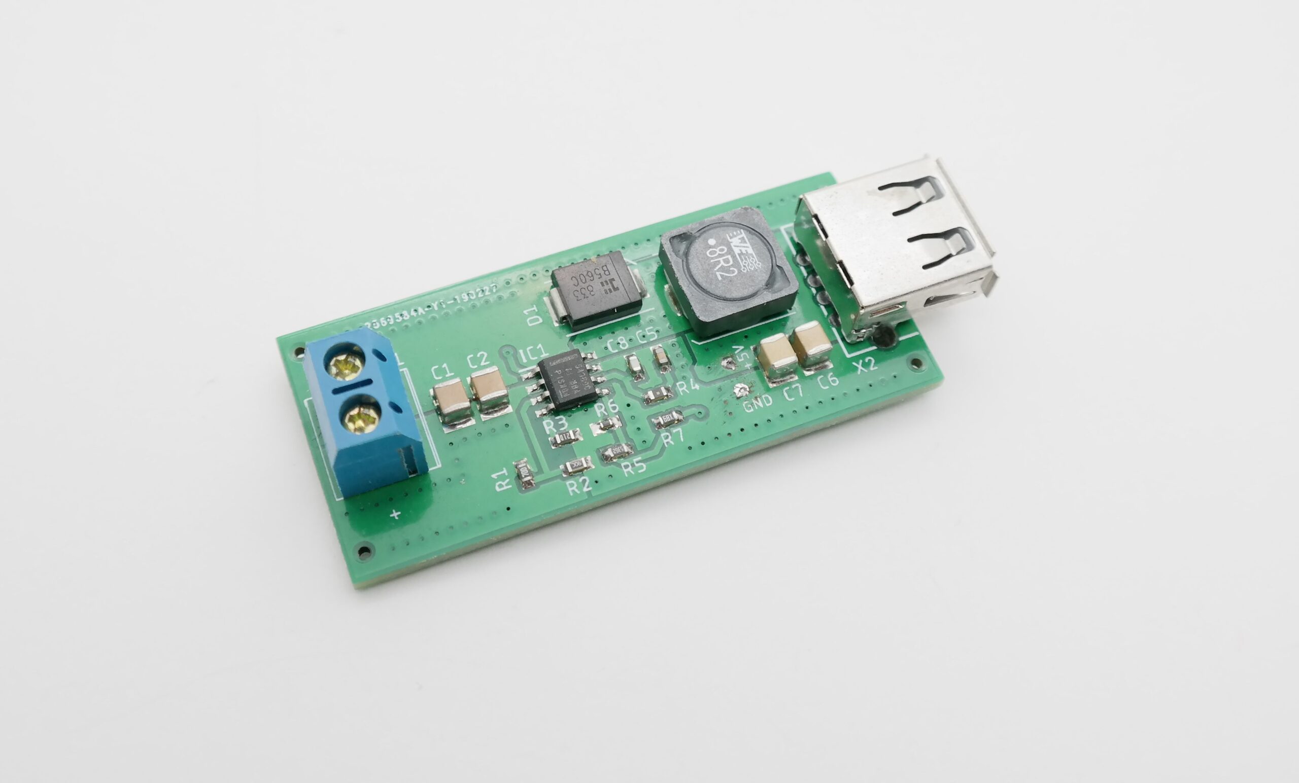
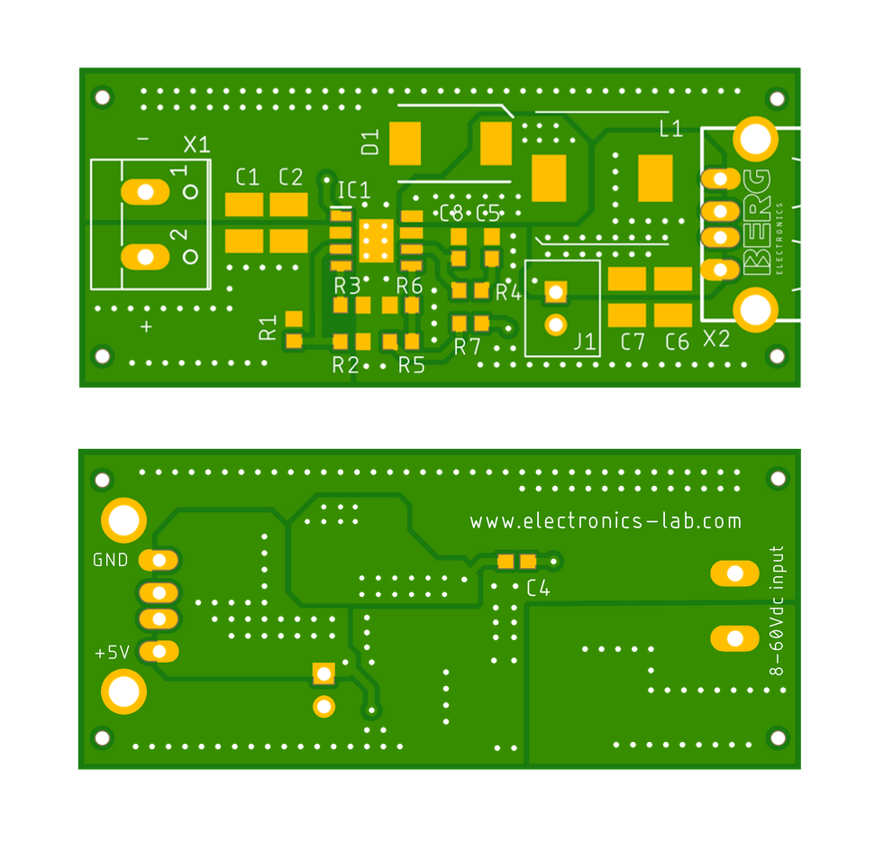
PCB
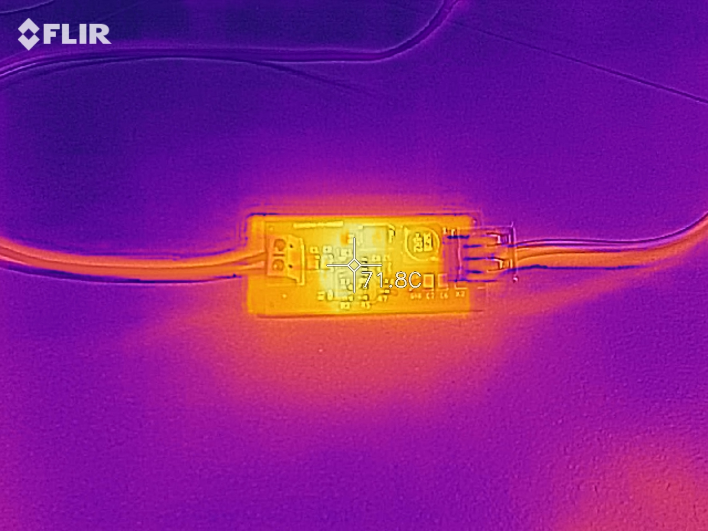
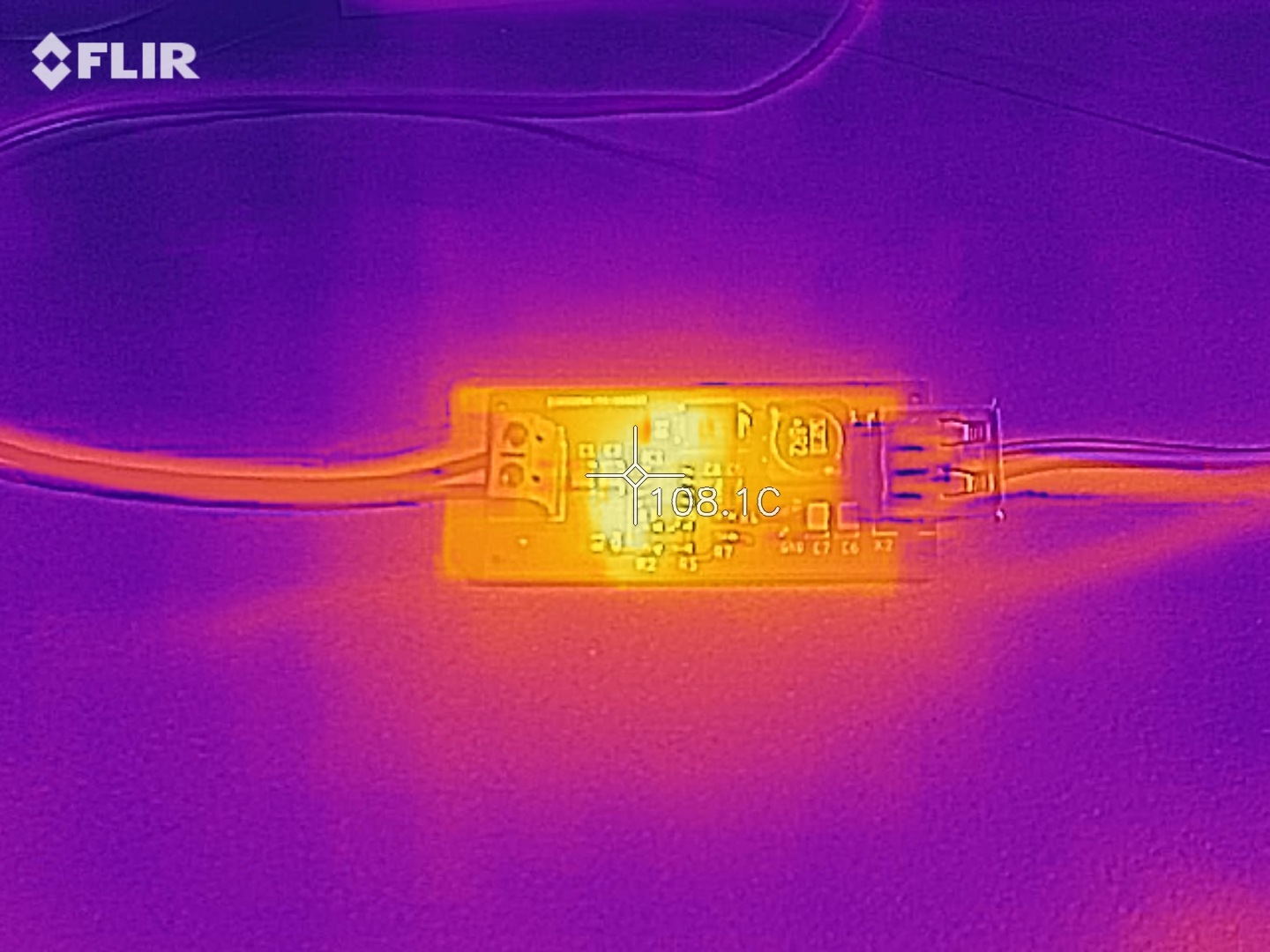
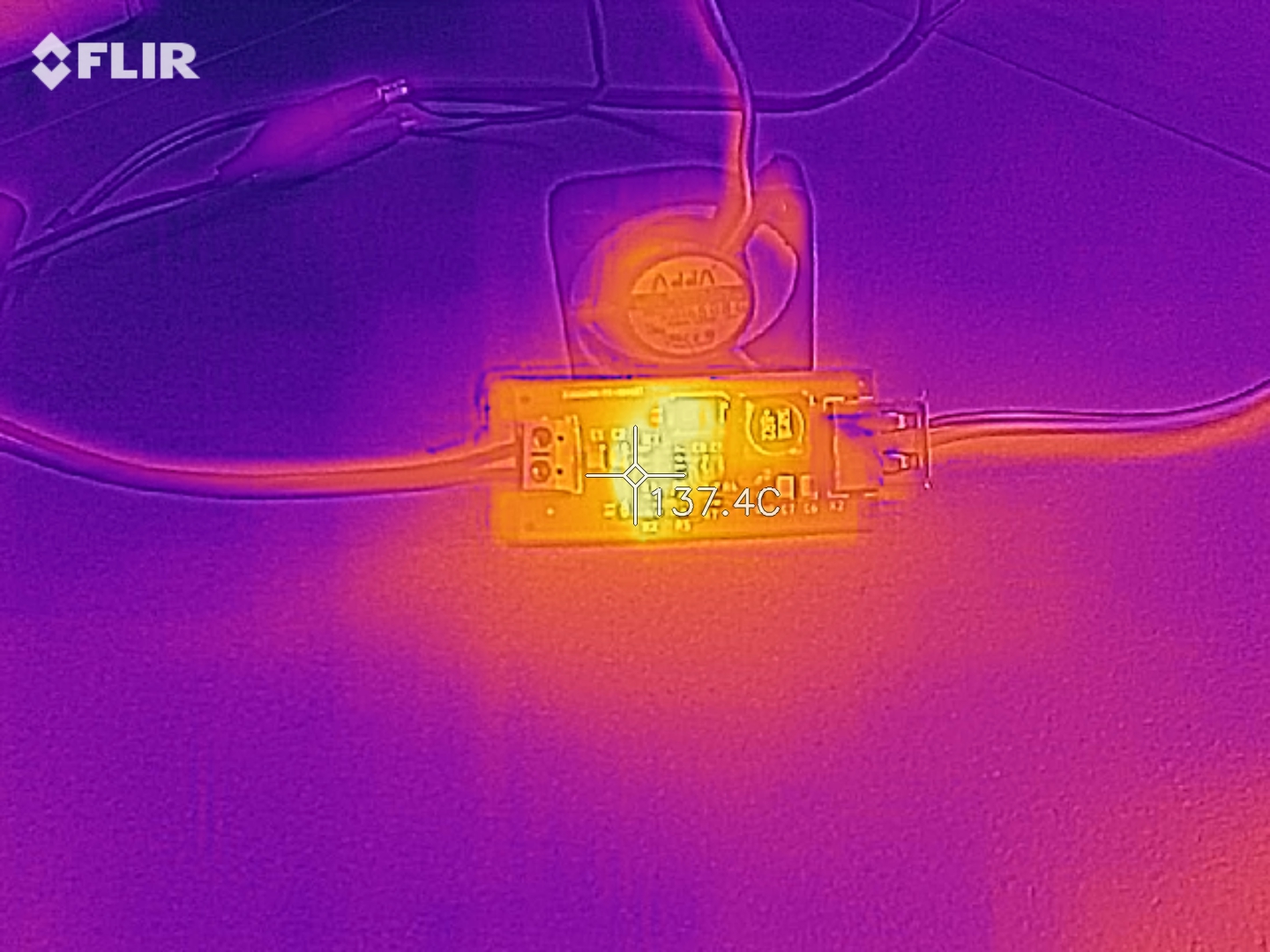
Thermal Image
You can see on the thermal images below that at 60V input – 5V @2A output the IC gets too hot (>105ºC) and if we go for higher outputs (2.5-3A) the IC gets in thermal cut-off. To avoid this situation you can use a small 5V FAN to blow air on the board or probably use a heatsink attached to the board.
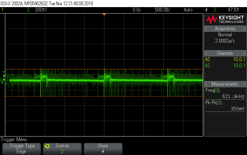
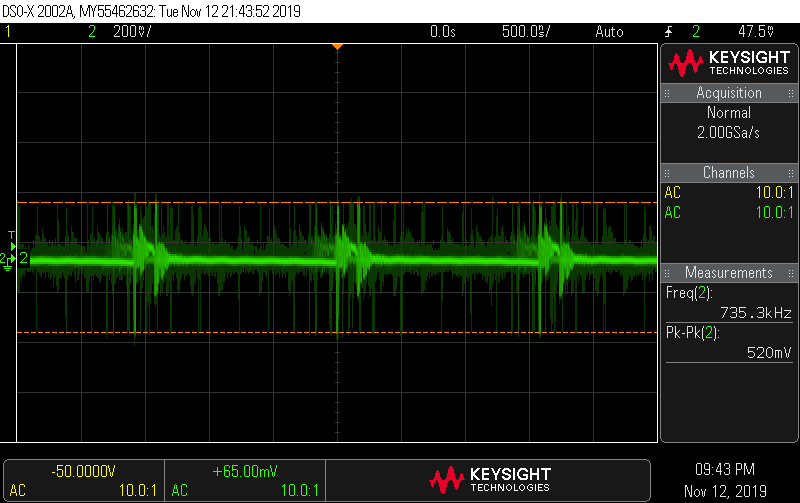
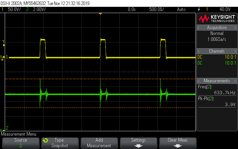
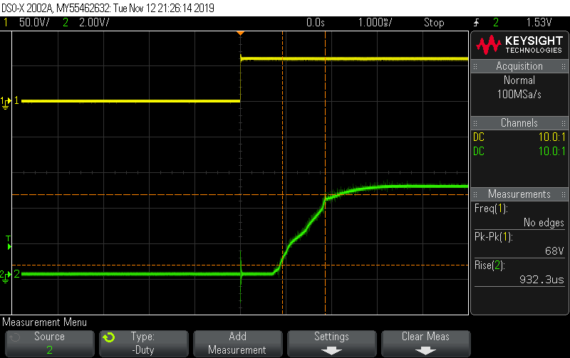
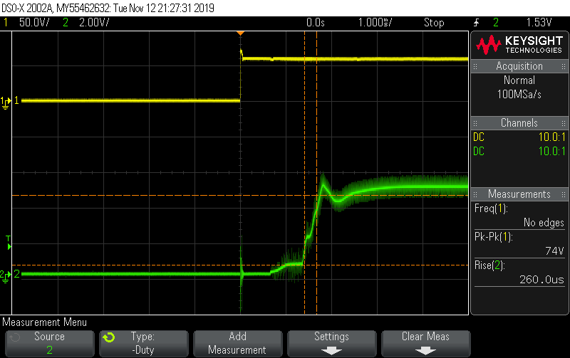
Measurements
The efficiency is calculated based on the (Pout/Pin)*100%. For 60V input and 5V @3A output the input current is 0.32A, so Pin=19.38W. Pout=5V*3A=15W, so e=77.39% with Pdis = 4.58W
Video
Photos