Four-Channel Digital Isolator – Reinforced – High Speed – Low-Power
The project presented here is a high-speed, low-power 4-channel digital galvanic isolator. This innovative solution enables the transfer of digital signals between circuits with different power domains, achieving an impressive power consumption of as little as 0.74mW per channel at a data rate of 1 Mbps, while operating on a 1.8V supply.
The project presented here is a high-speed, low-power 4-channel digital galvanic isolator. This innovative solution enables the transfer of digital signals between circuits with different power domains, achieving an impressive power consumption of as little as 0.74mW per channel at a data rate of 1 Mbps, while operating on a 1.8V supply. At the heart of this project is the MAX22445FAWE chip, which features reinforced isolation, allowing it to withstand a voltage rating of 5KV-RMS for 60 seconds. This robust design ensures reliable and secure signal transmission.
The project offers flexible configuration options, accommodating all possible unidirectional channel configurations to suit any 4-channel design. This versatility makes it an ideal solution for a wide range of applications, including SPI, RS-485, digital I/O, etc.
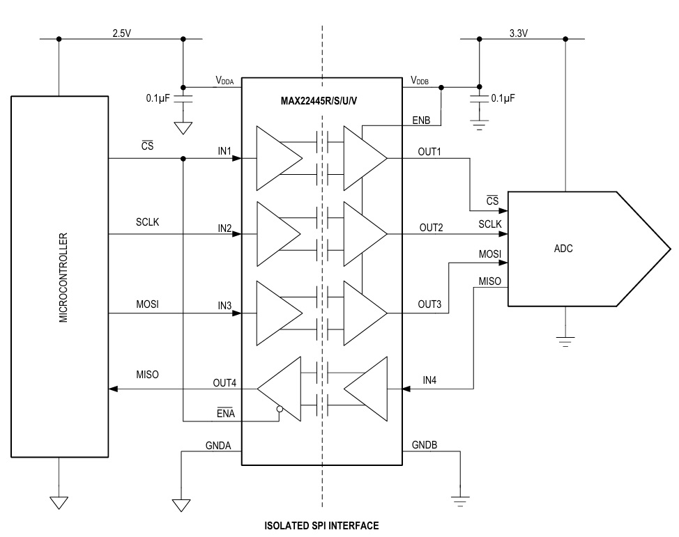
Notably, the output that enables the A side of the isolation can be connected to a shared SPI bus, allowing the CS signal to directly enable the MISO signal on the isolator. Additionally, all other output enables are traditional active-high, providing a convenient and straightforward interface.
Overall, this high-speed, low-power digital galvanic isolator project provides a reliable and efficient solution for transferring digital signals between circuits with different power domains, making it an attractive option for a variety of applications.
Features
- Power Supply A-Side 1.71V to 5.5V
- Power Supply B-Side 1.71V to 5.5V
- Power LED for both sides A and B
- SMA connectors for Inputs and Outputs for High-Speed Data Transfer
- Header Connector for Power
- Ferrite Bead On power line to prevent noise
- Reinforced Galvanic Isolation for Fast Digital Signals Up to 200Mbps Maximum Data Rate
- Withstands 5kVRMS for 60s (VISO)
- Continuously Withstands 1500VRMS (VIOWM)
- Withstands ±12.8kV Surge Between GNDA and
- GNDB with 1.2/50μs waveform
- High CMTI (50kV/μs, Typical)
- Low Power Consumption 0.74mW per Channel at 1Mbps with VDD = 1.8V
- 4mW per Channel at 1Mbps with VDD = 3.3V
- 2mW per Channel at 100Mbps with VDD = 1.8V
- 3 Direction Configurations
- Active-High or Active-Low Enable Inputs
- 2 Fixed Output Default States (High/Low)
- 4 x 3 mm PCB Mounting Holes
- PCB Dimensions 54.77 x 45.09 mm
Digital Isolation: The MAX22445 provides reinforced galvanic isolation for digital signals that are transmitted between two ground domains. The devices withstand differences of up to 5kVRMS for up to 60 seconds, and up to 2121VPEAK of continuous isolation.
Level-Shifting: The wide supply voltage range of both VDDA and VDDB allows the MAX22445 to be used for level translation in addition to isolation. VDDA and VDDB can be independently set to any voltage from 1.71V to 5.5V. The supply voltage sets the logic level on the corresponding side of the isolator.
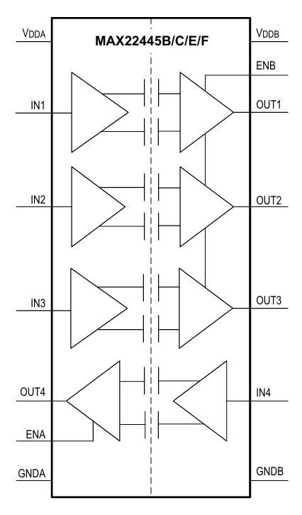
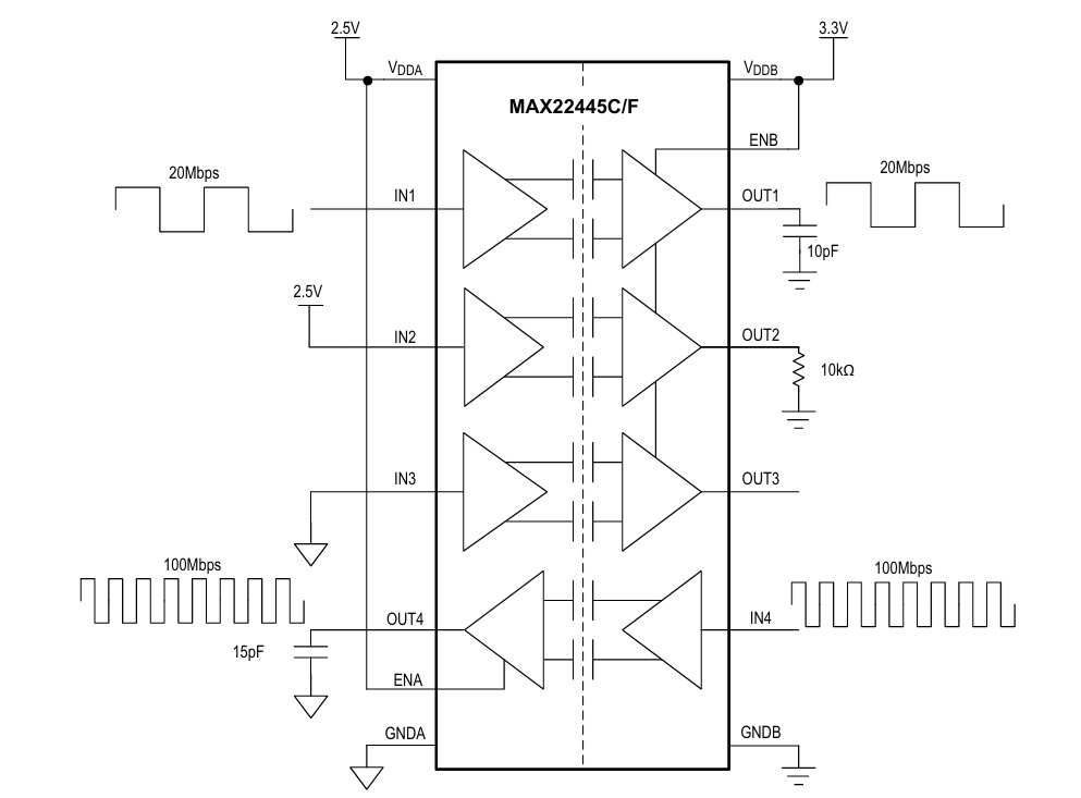
Unidirectional Channels: Each channel of the MAX22445 is unidirectional; it only passes data in one direction, as indicated in the functional diagram. The device features four unidirectional channels that operate independently with guaranteed data rates from DC up to 200Mbps. The output driver of each channel is push-pull, eliminating the need for pullup resistors. The outputs are able to drive both TTL and CMOS logic inputs.
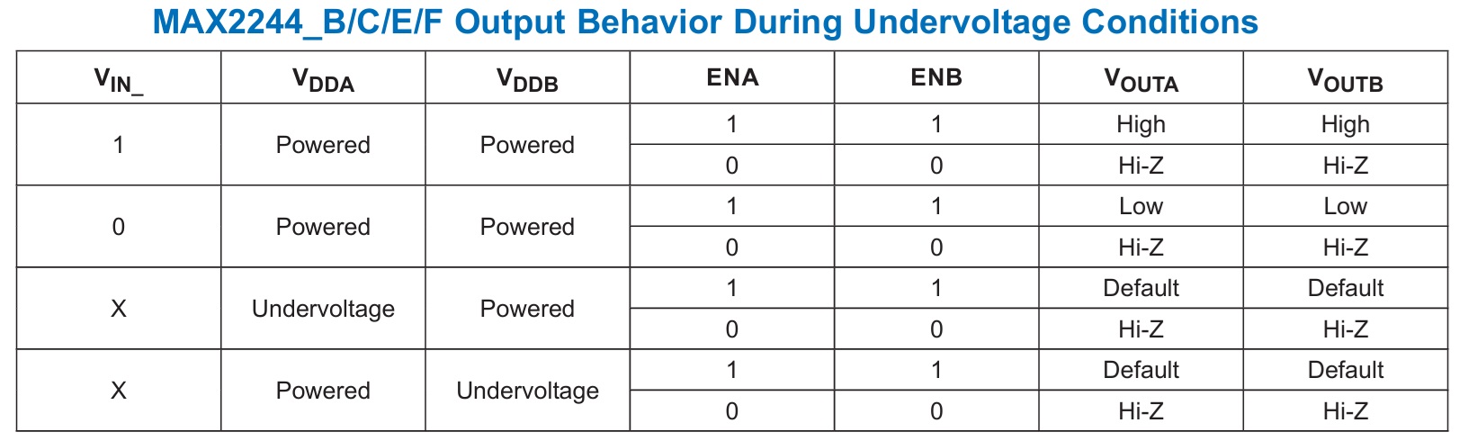
Start-up and Undervoltage-Lockout: The VDDA and VDDB supplies are both internally monitored for undervoltage conditions. Undervoltage events can occur during power-up, power-down, or during normal operation due to a sagging supply voltage. When an undervoltage condition is detected on either supply while the outputs are enabled, all outputs go to their default states regardless of the state of the inputs
Power-Supply Sequencing: The MAX22445 do not require special power supply sequencing. The logic levels are set independently on either side by VDDA and VDDB. Each supply can be present over the entire specified range regardless of the level or presence of the other supply.
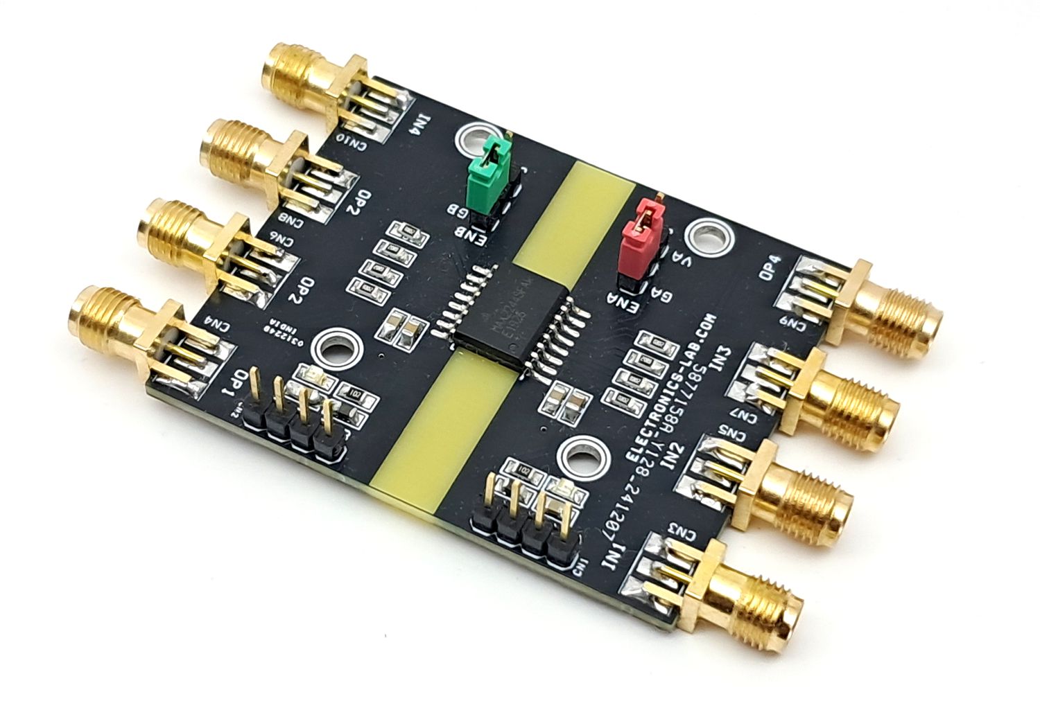
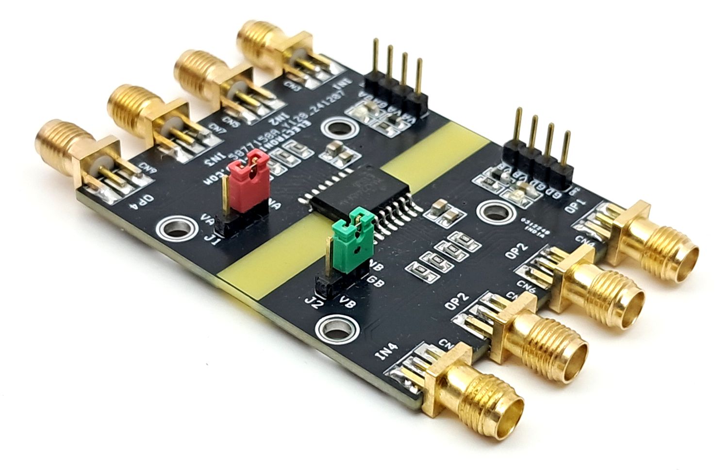
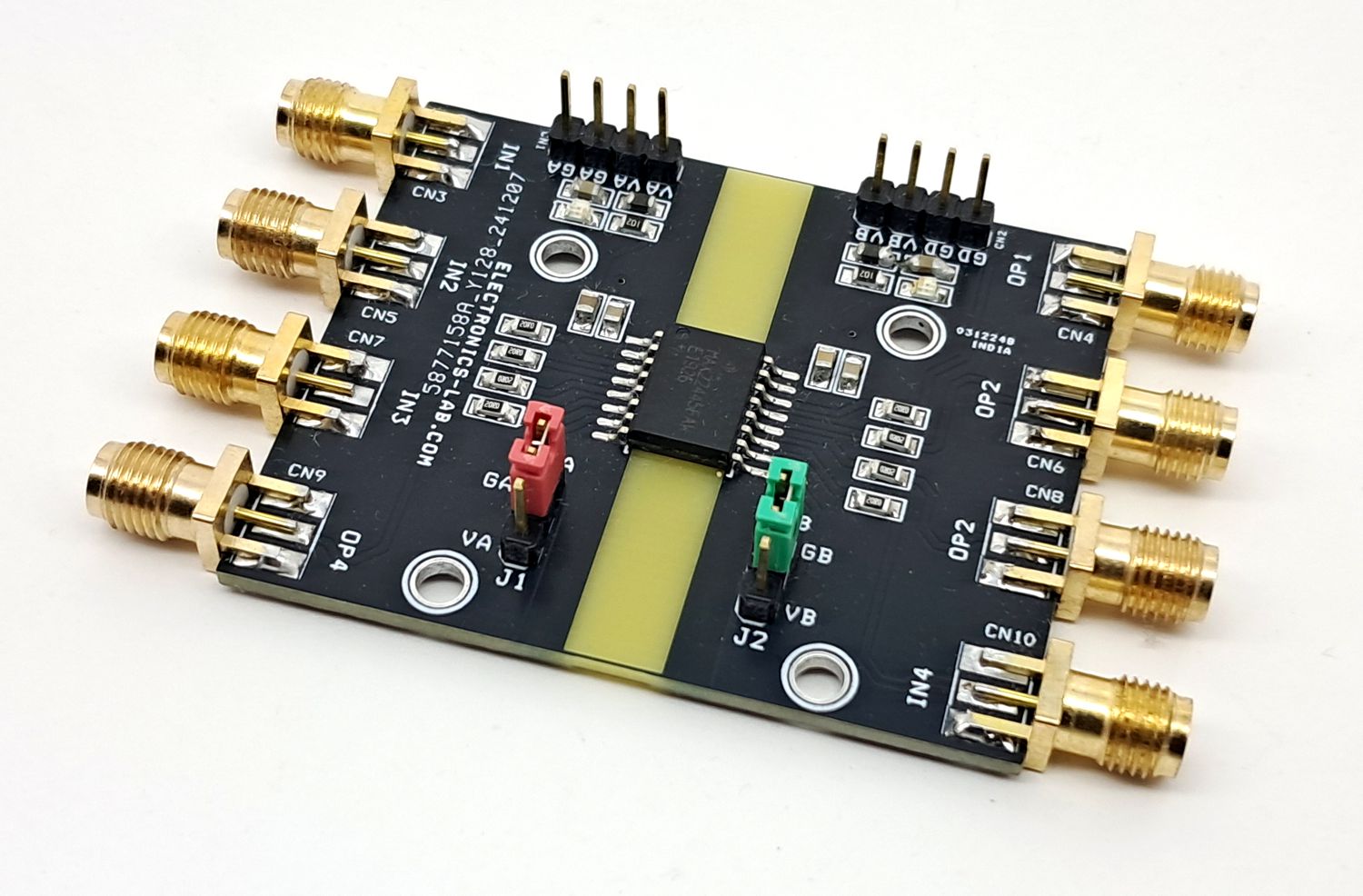
Jumpers
Jumper J1 and J2 are provided to enable or disable the output. Jumper J1 for A side and Jumper J2 for B side.
- MAX22445FAWE chip supports data rates up to 200Mbps, enables polarity Low Active-High
- MAX22445MAWE chip supports data rates up to 25Mbps
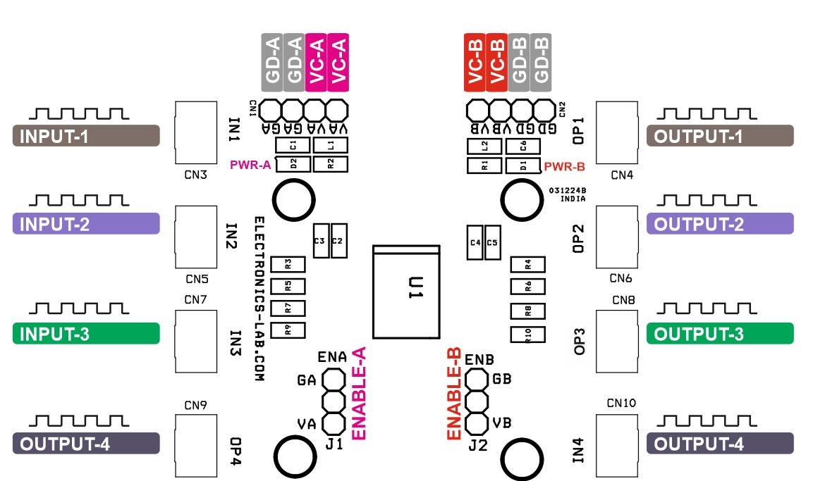
Connections
- CN1 Power A Side: Pin 1,2 = VCC-A 1.71V to 5.5V, Pin 3,4 = GND
- CN2 Power B Side: Pin 1,2 = VCC-B 1.71V to 5.5V, Pin 3,4 = GND
- CN3 Input-1 (A Side)
- CN5 Input-2 (A Side)
- CN7 Input-4 (A Side)
- CN9 Output-1 (A Side)
- CN4 Output-1 (B Side)
- CN6 Output-2 (B Side)
- CN8 Output-3 (B Side)
- CN10 Input-4 (B Side)
- D1: Power LED A-Side
- D2: Power LED B-Side
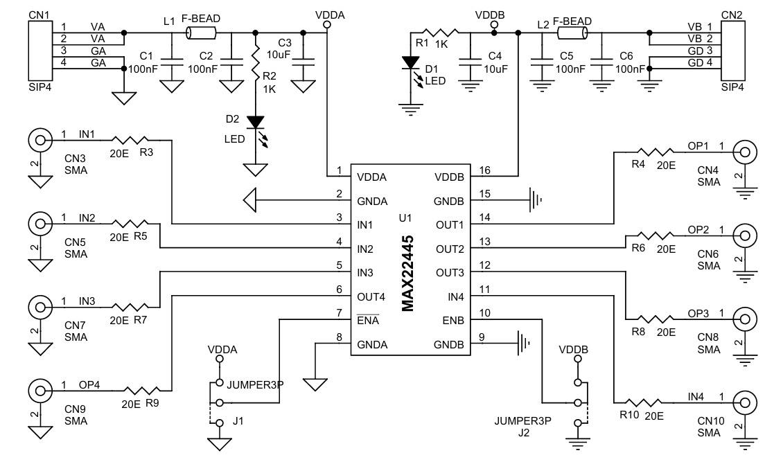
Schematic
Parts List
| NO | QNTY | REF. | DESC. | MANUFACTURER | SUPPLIER | SUPPLIER PART NO |
|---|---|---|---|---|---|---|
| 1 | 2 | CN1,CN2 | 4 PIN MALE HEADER PITCH 2.54MM | WURTH | DIGIKEY | 732-5317-ND |
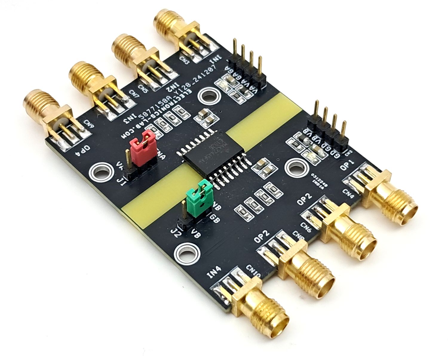
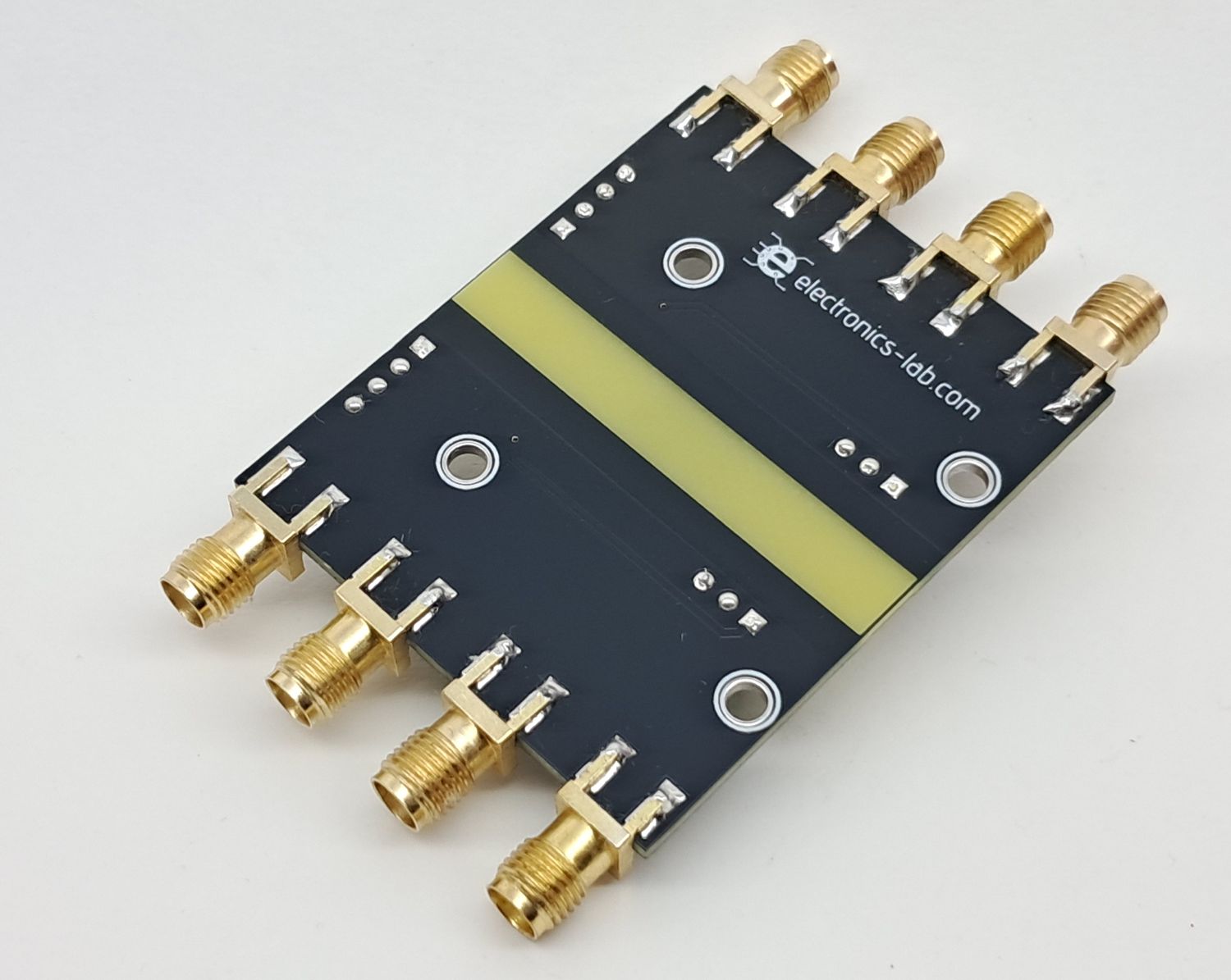
| 2 | 8 | CN3,CN4,CN5,CN6,CN7,CN8,CN9,CN10 | SMA CONNECTORS | RF SOLUTIONS | DIGIKEY | CON-SMA-EDGE-S-ND |
| 3 | 4 | C1,C2,C5,C6 | 100nF/25V CERAMIC SMD SIZE 0805 | YAGEO/MURATA | DIGIKEY | |
| 4 | 2 | C3,C4 | 10uF/25V CERAMIC SMD SIZE 0805 | YAGEO/MURATA | DIGIKEY | |
| 5 | 2 | D1,D2 | LED RED SMD SIZE 0805 | OSRAM | DIGIKEY | 475-1278-1-ND |
| 6 | 2 | J1,J2 | 3 PIN MALE HEADER PITCH 2.54MM | WURTH | DIGIKEY | 732-5316-ND |
| 7 | 2 | L1,L2 | FERRITE BEAD 600OHM SMD SIZE 0805 | LAIRD | DIGIKEY | 240-2390-1-ND |
| 8 | 2 | R1,R2 | 1K 5% SMD SIZE 0805 | YAGEO/MURATA | DIGIKEY | |
| 9 | 8 | R3,R4,R5,R6,R7,R8,R9,R10 | 20E 5% SMD SIZED 0805 | YAGEO/MURATA | DIGIKEY | |
| 10 | 1 | U1 | MAX22445 | ANALOG DEVICE | DIGIKEY | MAX22445FAWE+-ND |
| 11 | 2 | J1,J2 SHUNT | SHUNT FOR JUMPER J1,J2 | SULLINS CONNEC | DIGIKEY | S9001-ND |
Connections
Block Diagram
Example Circuit
Isolated SPI Example Circuit
Output Table
Gerber View
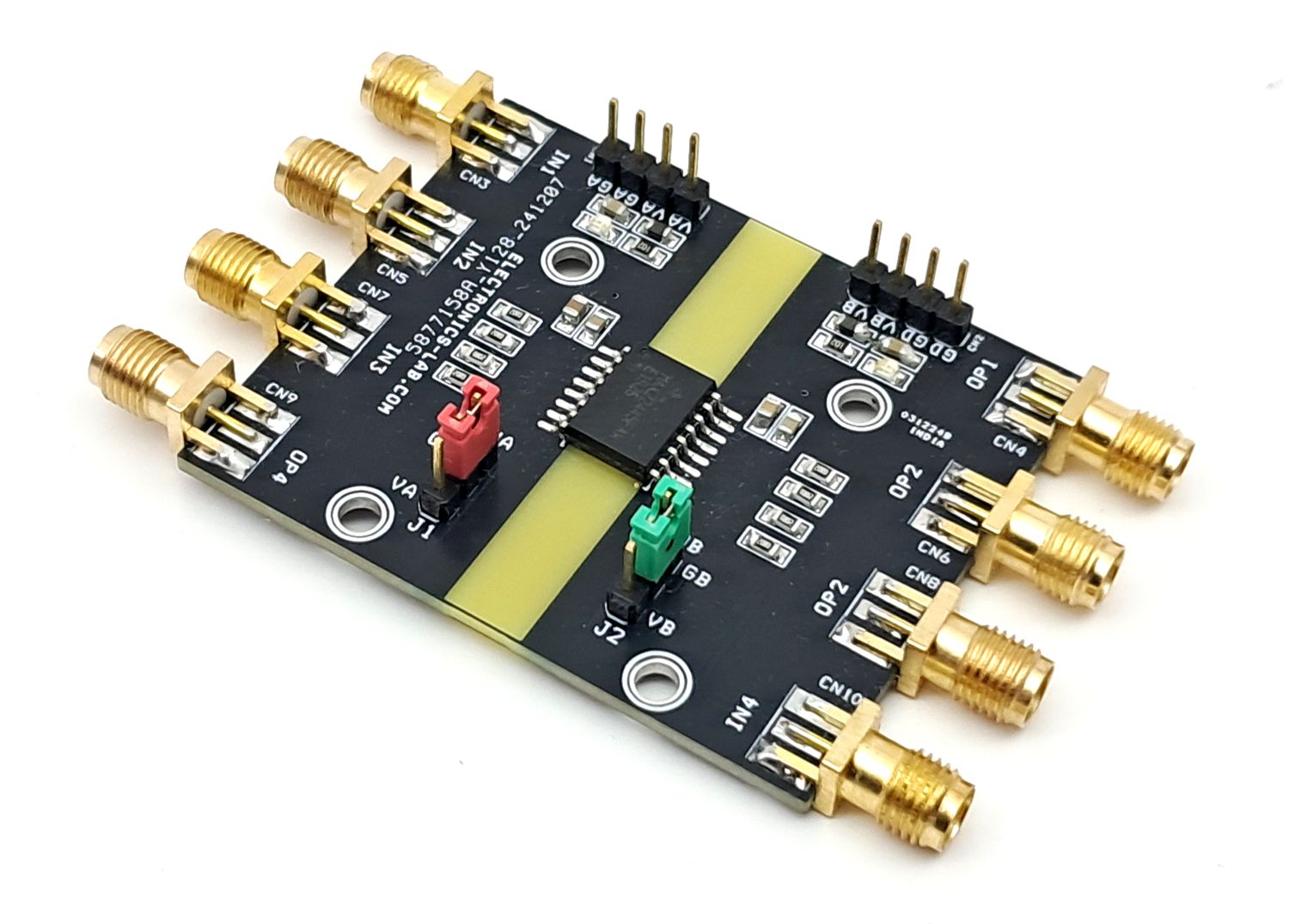
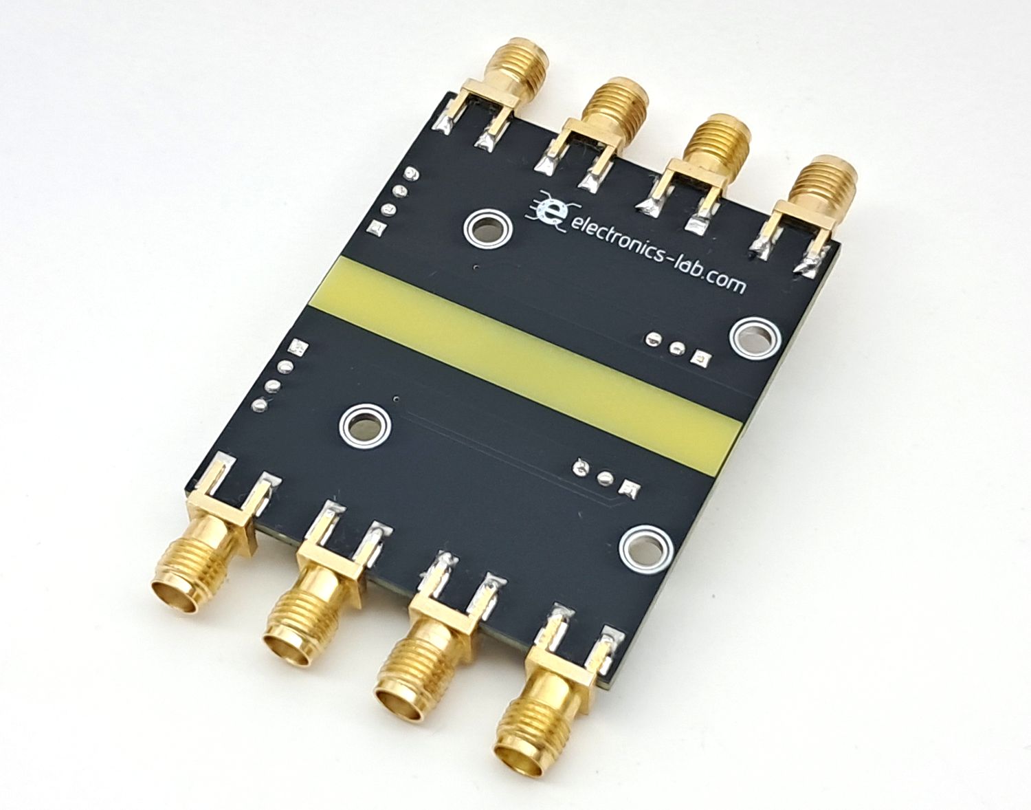
Photos
Impressive specs! The MAX22445’s reinforced isolation and low power use make it perfect for compact, high-reliability mixed-signal or industrial applications.