How To Program ATtiny13/ATtiny13a using Arduino IDE
Introduction Despite ATtiny series is considered extremely cheap and useful, still there is a lack of projects and tutorials about it. In this tutorial, you will learn how to start building applications using ATtiny13 microcontroller programmed using Arduino IDE.
Introduction
Despite ATtiny series is considered extremely cheap and useful, still there is a lack of projects and tutorials about it. In this tutorial, you will learn how to start building applications using ATtiny13 microcontroller programmed using Arduino IDE.
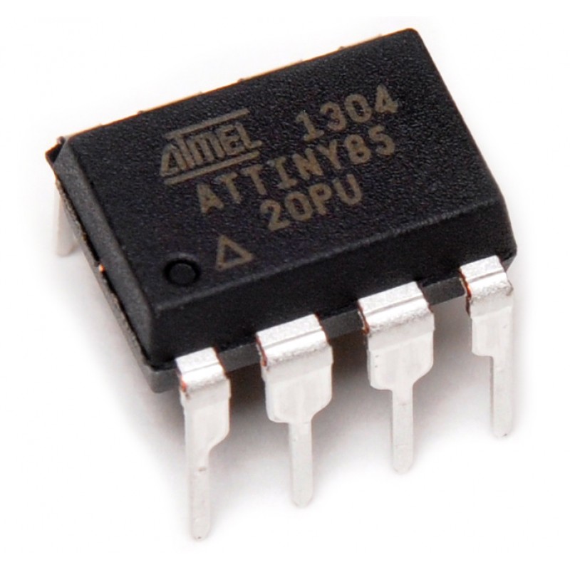
First of all, ATtiny13 is a low-power CMOS 8-bit microcontroller based on the AVR enhanced RISC architecture. By executing powerful instructions in a single clock cycle, the ATtiny13 achieves throughput approaching 1 MIPS per MHz allowing the system designer to optimize power consumption versus processing speed. After the acquisition of Atmel by Microchip, the new ATtiny13 is still in production.
Parts you will need
- Arduino (Uno or any other Arduino)
- ATtiny13 or 13a
- Breadboard
- Jumper Wires
The Circuit
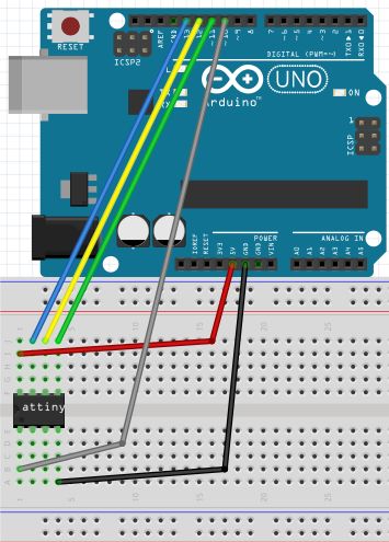
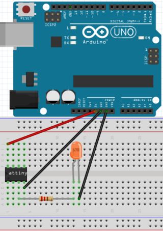
In order to connect the hardware you should first orient the ATtiny as shown in the image.
First, connect Arduino 5V to ATtiny Pin 8. Respectively, connect GND to Pin 4, Pin 13 to Pin 7, Pin 12 to Pin 6, Pin 11 to Pin 5, and finally Pin 10 to Pin 1.
Programming the ATtiny13
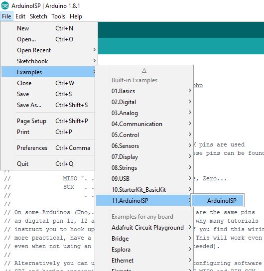
To program ATtiny13 we should set our Arduino as a programmer. This could happen by uploading ArduinoISP sketch to Arduino following this path (Files -> Examples -> ArduinoISP) in the IDE.
Now our Arduino is ready to program ATtiny 13, but still we have to set up the ATtiny by installing its core files. In this tutorial, files by sleepmanj are preferred.
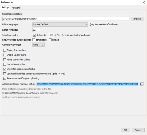
To install these files, open your Arduino IDE and navigate to the files drop-down menu, then select preferences. Paste this URL “https://raw.githubusercontent.com/sleemanj/optiboot/master/dists/package_gogo_diy_attiny_index.json” where it says “Additional Boards Manager URLs:”. If you already have a URL here and want to add more, separate the URLs with a comma and a space.
Now, navigate to tools-board and click on Boards Manager…. Now scroll down until you see DIY ATtiny and click the install button.
Burning the Bootloader to the Attiny
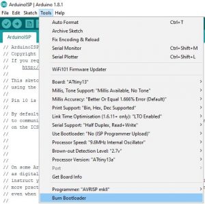
In fact, the bootloader is a piece of firmware in your microcontroller that allows installing new firmware via serial communication. In order to start programming ATtiny 13, we must burn Bootloader to it. There are two steps to achieve this: first, go to Tools-Board and select ATtiny13, and second, click the Burn Bootloader button at the bottom of the tools drop-down menu.
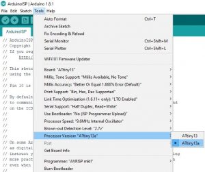
You should pay attention to your ATtiny version, navigate to Tools-Processor Version and select either ATtiny13 or ATtiny13a depending on your chip.
After burning the Bootloader, our ATtiny is now ready to be programmed. You can try now Arduino IDE examples like the Blink sketch.
To make sure that Blink will work correctly, you should first check the diagram below.
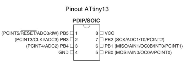
Right here, Pin 3 is defined in hardware as PB4, now let’s take a look at the edited code:
//We will replace "LED_BUILTIN" with "4" since ATtiny does not have a built-in led!
void setup() {
  // initialize digital Pin 3 of ATtiny 13(defined in hardware as 4) as an output.
  pinMode(4, OUTPUT);
}

// the loop function runs over and over again forever
void loop() {
  digitalWrite(4, HIGH);   // turn the LED on (HIGH is the voltage level)
  delay(1000);                       // wait for a second
  digitalWrite(4, LOW);    // turn the LED off by making the voltage LOW
  delay(1000);                       // wait for a second
}
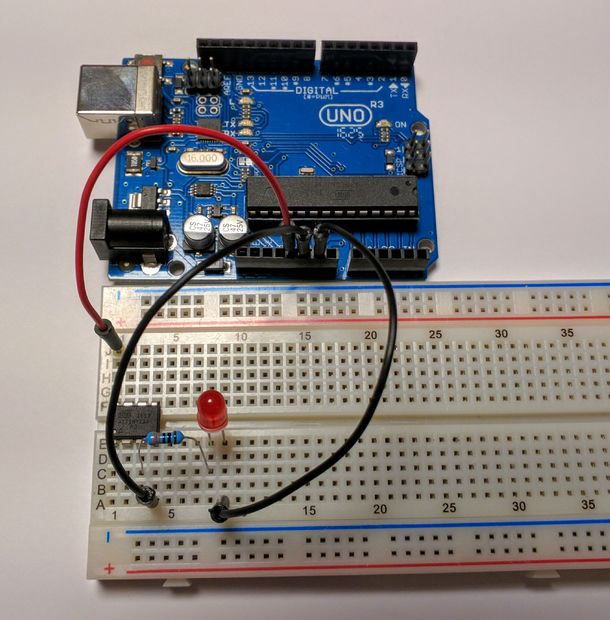
Next, modify your circuit by adding an LED between Pin 3 and GND with a suitable resistor as shown in the picture.
Troubleshooting
If you faced any issues while building this project, you can check this list to troubleshoot your project:
• Double check all of your connections and your orientation of the ATtiny and LED.
• Re-upload the ArduinoISP sketch to your Arduino.
• Connect a 10uf electrolytic capacitor between ground and reset on your Arduino. Make sure to plug in the capacitor in the correct orientation, negative goes to ground.
• Connect any large capacitor between the 5v and ground on the breadboard, this will help smooth out any voltage spikes.
• Make sure enough power is getting to the Arduino that is programming the ATtiny, a 9 volt battery might not work.
• Switch out your Arduino with a different Arduino
• Make sure you’re using an up to date IDE and up to date core files
• Click on tools and make sure the drop down menu looks the same as the menu shown in the Burn the Bootloader” step. If something is different, change it and re-burn the bootloader.
You also may need these components while trying to figure out what’s wrong: 10uf electrolytic capacitor a large electrolytic capacitor (>100uF)
You are now all set, it is time to test new ideas and applications with ATtiny programmed using Arduino IDE!
References
- This tutorial is inspired by NotoriousRapper2Chainz on Instructables, you can see more details on the original article by checking this link.
Two remarks:
1. You don’t actually burn a bootloader to ATtiny (no space for it), you’re just setting “fuse bits” (frequency, brown out protect etc.). Thus if you don’t need to change factory default settings, no need to “burn fuses”.
2. If you just need ATtiny13 support, I recommend small and efficient MicroCore https://github.com/MCUdude/MicroCore
I stand corrected, the DIY AVR core mentioned in the article seems to be the better option. It also supports using millis and ISR(WDT_vect) at the same time (which MicroCore doesn’t).
Thanks for your comment and positive input.
It also takes up much more flash space. Not that good for a t13
Thanks for your comment and positive input. how to get it
Thank you so much for your support
Hi!
You wrote, the boot loader allows installing new firmware via serial communication. How do you mean it? Because after I have uploaded the boot loader I cannot upload any Arduino sketch file via e.g. a USB-serial converter, that I can do in case of ATMEGA 328P. Did I misunderstood something?
Thanks in advance!
Thanks for your guide, I have a problem…
After set Arduino like a programmer, after load the bootloader… when I try to load the scketc, thae Arduino ide give me an error ” to load is needed a programmer”….
I’ve tried a lot of setting ,but the problem seems to be that the IDE don’t see the Arduino like a programmer, it can due to by the name ” DIY ATtiny: Arduino as ISP” when normally it is wrote ” Arduino as ISP”?
I solved: to program the attiny should send the sketch by programmer. Sketch-send by programmer and it is done! Hope this it will be useful to someone.
Can you be more specific, or upload a screen if possible ?
Still there )). The statements about bootloader here are confusing (if to be polite), especially for those whom this article appeals to. It would be fine if the author takes into consideration that has been commented here by brunoguy, learns the subject first, and makes edits to the article, mainly positive, but misleading in this point.