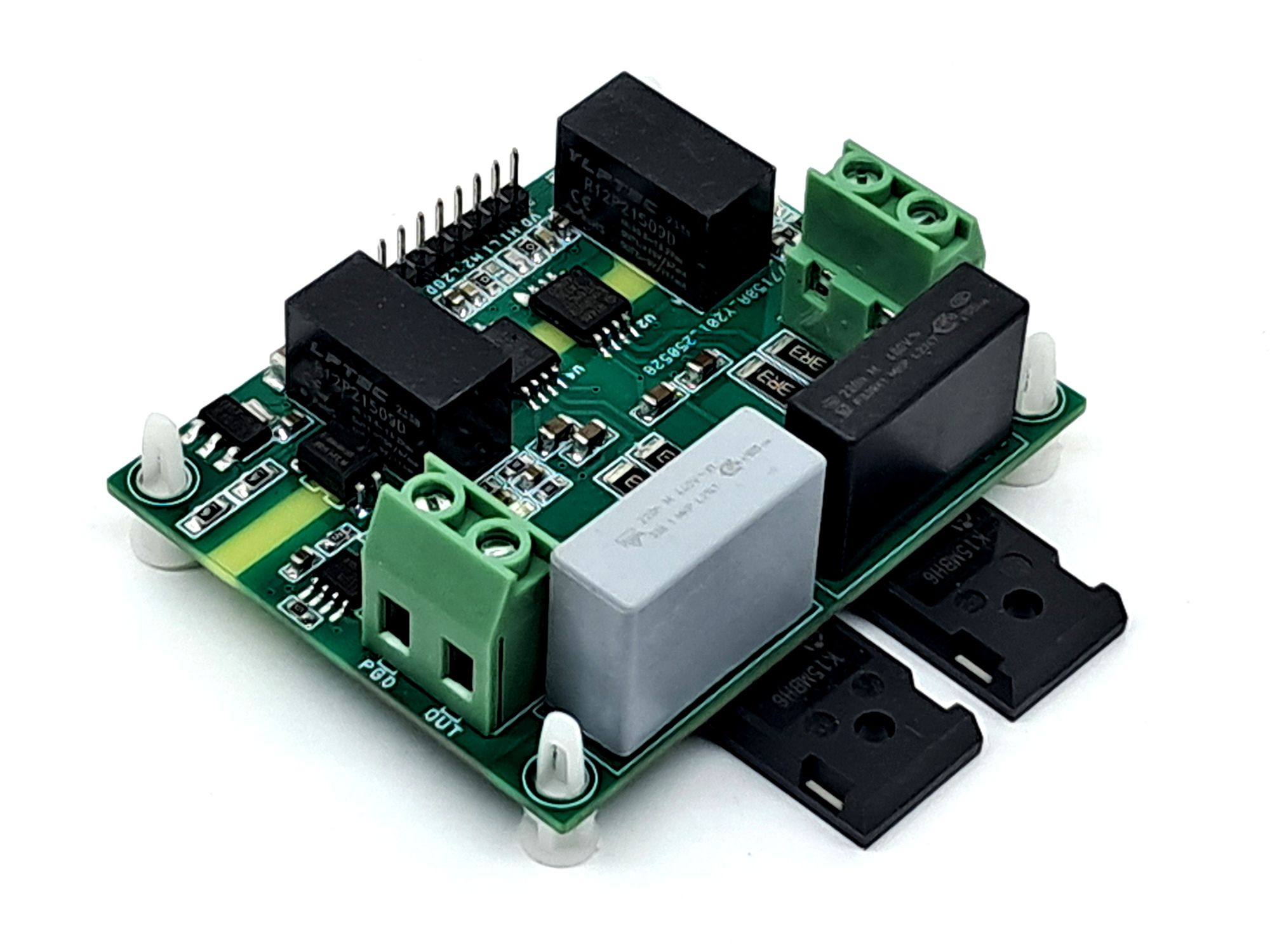
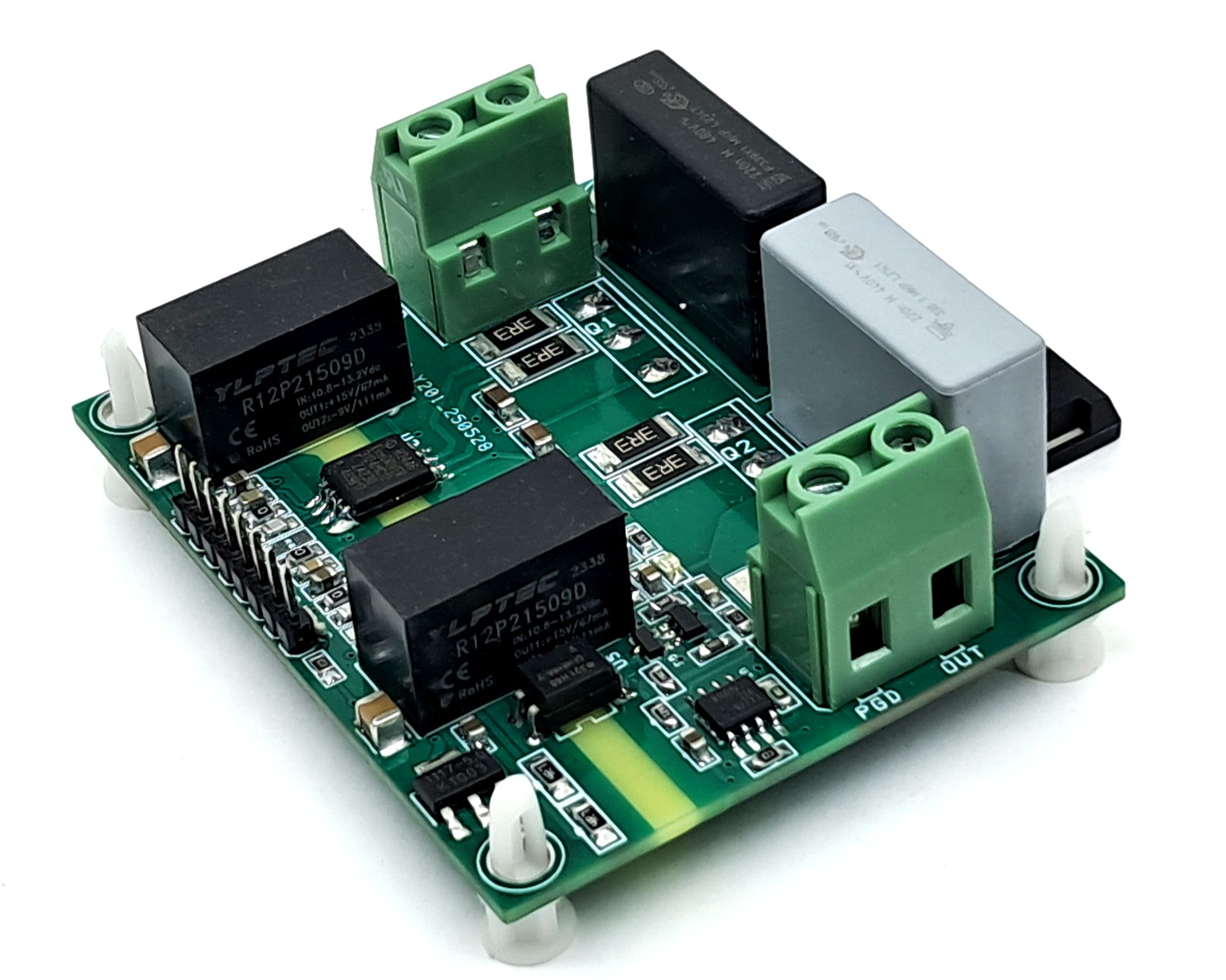
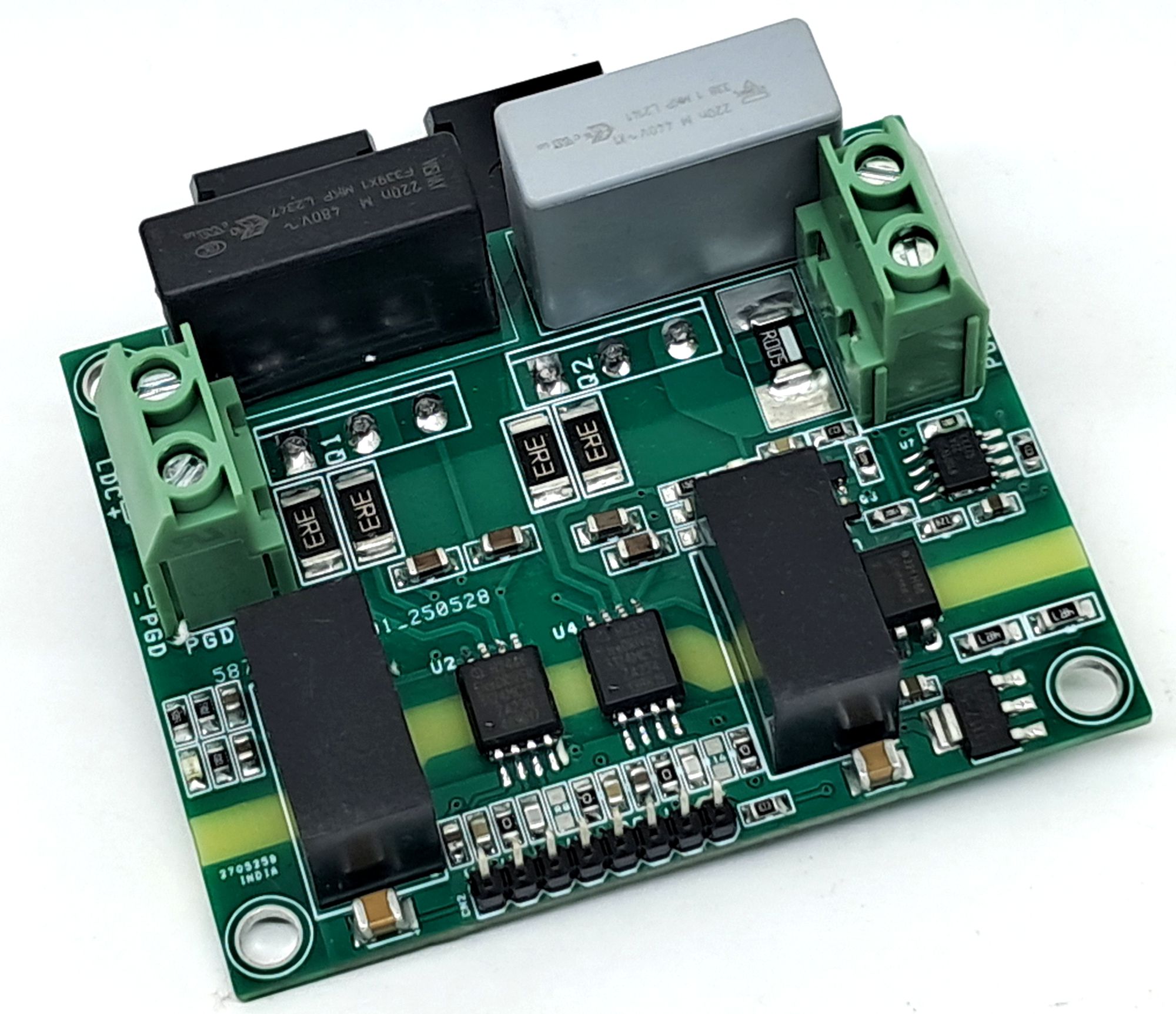
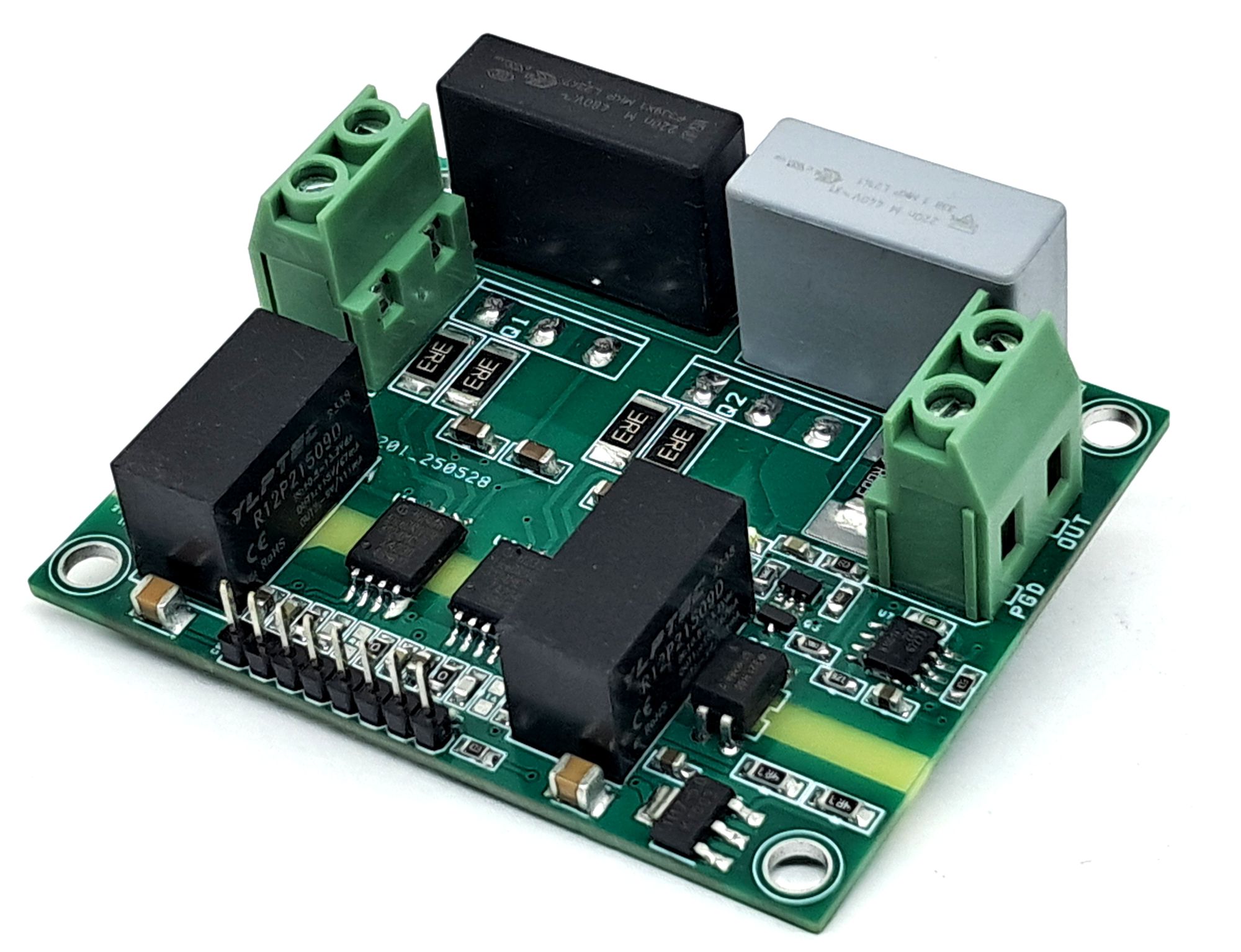
Isolated IGBT Half-Bridge Gate Driver Module
Isolated Half-Bridge: 1ED3124MC12H ICs, +15V/-9V supply, IGBTs, and shunt-based over-current detection.
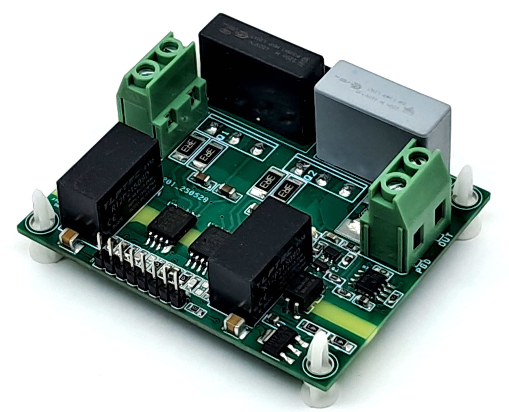
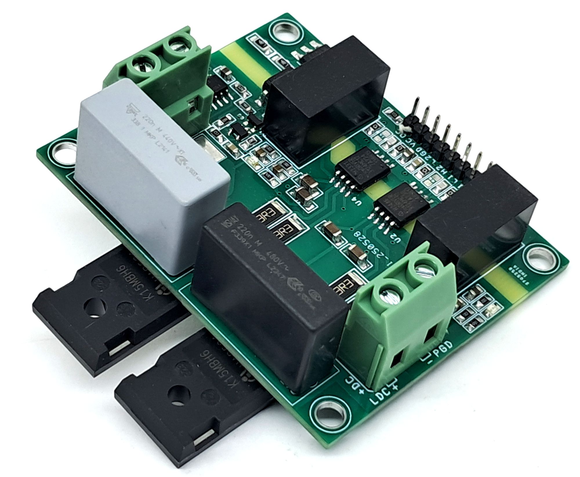
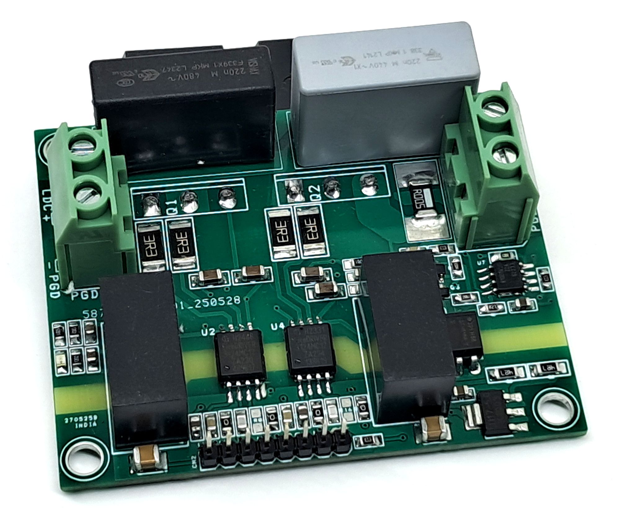
This is a fully isolated half-bridge gate driver module that can be configured according to the user’s voltage and current requirements. The design consists of two galvanically isolated single-channel gate driver 1ED3124MC12H ICs and a dedicated 2X isolated DC-DC power supply that provides a bipolar output of +15 V / –9 V, 2X IKW15N120BH6 IGBT, and LMV331 comparator and shunt resistor for over current detection.
The board is configured by default for IGBT applications; however, it can also be configured to drive MOSFETs and SiC MOSFETs. Users can select the appropriate power device (IGBT, MOSFET, or SiC MOSFET) based on the required voltage level, power rating, and switching frequency. Suitable Pin to pin compatible RECOM DC-DC converter for MOSFETS, SiC MOSFET.
The gate driver IC can also be chosen according to the gate charge and capacitance of the selected device to ensure optimal switching performance. A list of compatible driver ICs and power device part numbers is provided below for reference.
Compatible Gate Driver IC Options
The board can also accommodate lower-current compatible devices:
- 1ED3120MC12H – 5.5 A source/sink, 8.0 V UVLO
- 1ED3121MC12H – 5.5 A source/sink, 10.5 V UVLO
- 1ED3123MC12H – 14 A source/sink, 8.0 V UVLO
- 1ED3124MC12H – 14 A source/sink, 10.5 V UVLO
- 1ED3131MC12H – 5.5 A source/sink, 180 ns minimum input pulse suppression
Features
- Load Supply Up to 900V DC
- Gate Driver Power 12V DC
- On Board 5V Regulator to drive Gate Driver Input Side Circuitry
- D1 and D2 Power LED DC-DC Output
- Over Current Detection/Alarm Circuit (Isolated Output)
- Screw Terminals for Load and Load Power
- CMOS-compatible input thresholds (3 V to 15 V)
- Compatible with 3.3 V microcontrollers
- Header Connector for Input Signal, Logic Power and Fault Output
- 4 x 4 mm PCB Mounting Holes
- PCB Dimensions 71.12 x 57.15 mm
Core Components
The module is based on:
- 2× 1ED3124MC12H isolated gate driver ICs
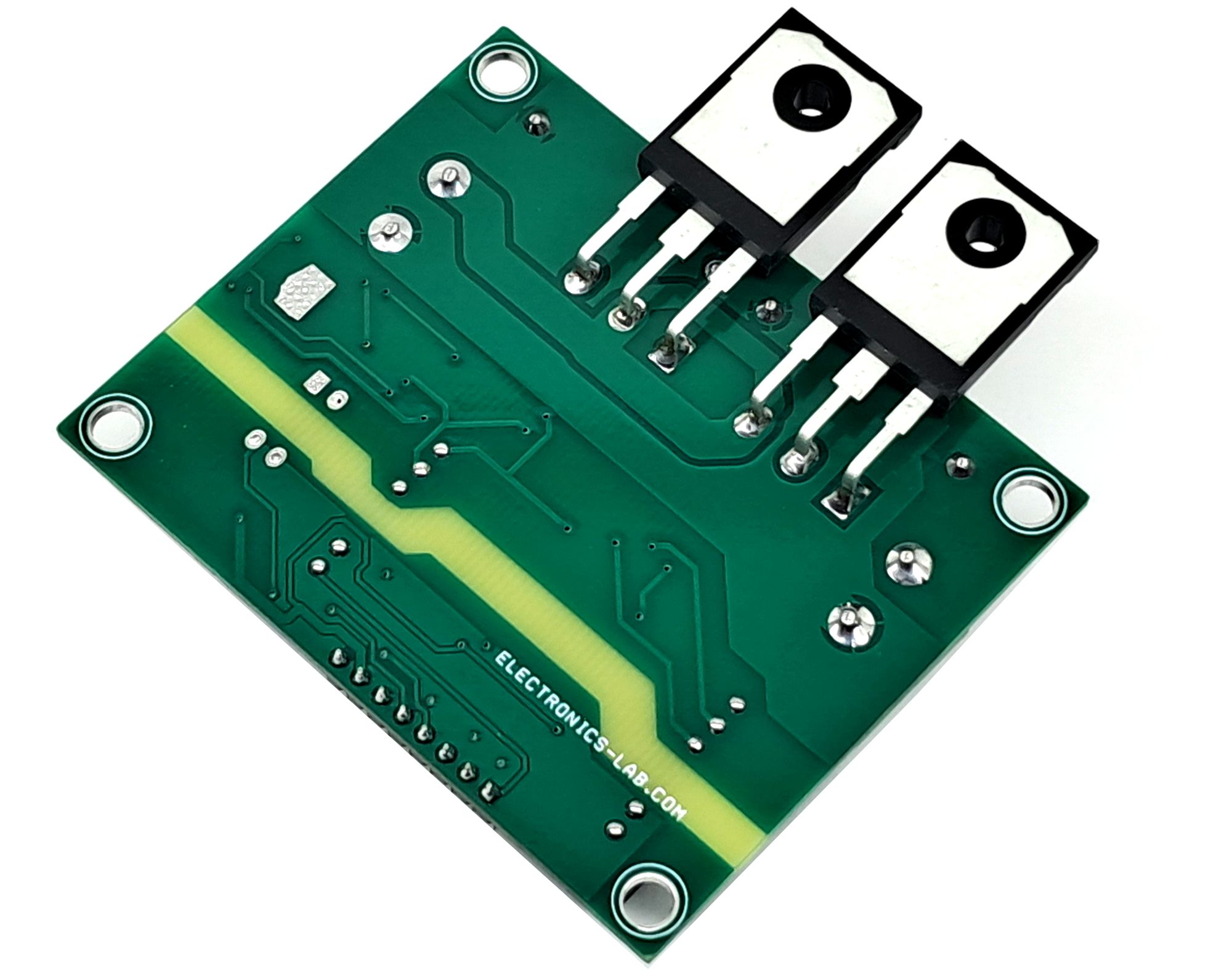
- 2X IKW15N120BH6 – 1200 V, 15 A high-speed IGBT with anti-parallel diode (TO-247)
- R12P21509D 2W isolated DC-DC converter
Logic Input Modes
The driver supports two selectable input modes:
- Non-Inverting Mode
- IN+ controls the driver output
- IN– is tied to LOW
- Inverting Mode
- IN– controls the driver output
- IN+ is tied to HIGH
A minimum input pulse width is implemented internally to suppress unwanted glitches and noise pulses.
The compact module is designed to control half-bridge IGBTs, delivering a high peak gate drive current of up to 14 A. It supports both non-inverting and inverting input configurations, with a defined minimum input pulse width to suppress noise and glitches.
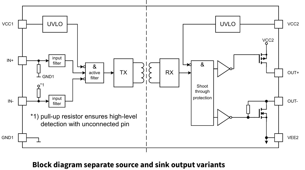
The output stage of gate driver chip utilizes MOSFETs to provide true rail-to-rail drive capability, ensuring tight control of the gate voltage during normal operation and short-circuit events. This design supports a wide range of IGBT voltage classes and is optimized for high-frequency switching applications.
The module has been tested with a 1200 V, 15 A dual IGBT configuration (2× IGBTs) and is suitable for DC bus voltages up to 900 V DC.
High-power screw terminals are provided for both the DC supply and load connections. These terminals are designed to safely handle high voltage and high current, ensuring reliable operation in demanding power applications.
Gate Driver Output Stage
- The output section uses MOSFETs to provide rail-to-rail drive capability. This ensures:
- Tight gate voltage control during turn-on and short-circuit events
- Stable operation as long as the driver supply voltage remains within limits
- Low internal voltage drops, allowing IGBT switching characteristics to be primarily defined by the external gate resistor
- Reduced power dissipation within the driver IC
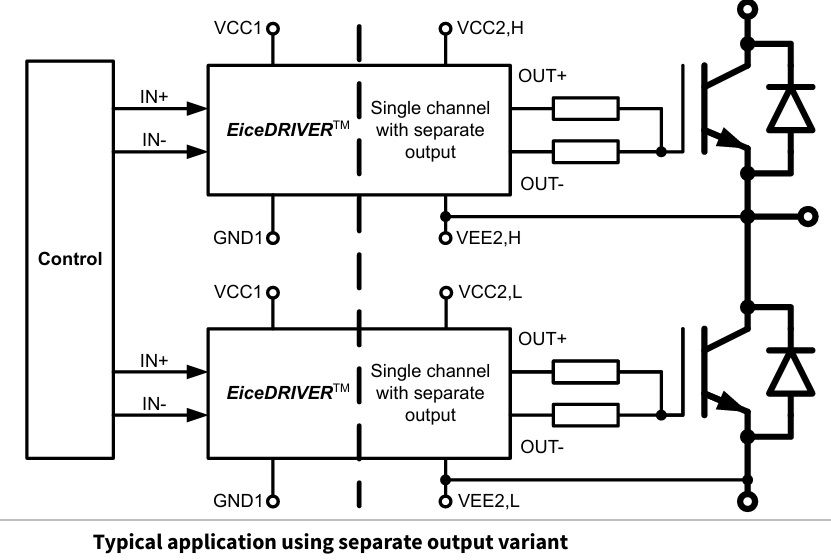
- The driver provides separate source and sinks outputs for precise gate control.
- Isolation and Electrical Characteristics
- The gate driver IC features:
- 7 kV (RMS) isolation rating
- Galvanically isolated coreless transformer technology
- Separate source and sink outputs
- Driver-side and logic-side undervoltage lockout (UVLO)
- Active shutdown function
- CMOS-compatible input thresholds (3 V to 15 V)
- Compatible with 3.3 V microcontrollers
The IC is suitable for driving:
- 600 V IGBTs
- 650 V IGBTs
- 1200 V IGBTs
- 1700 V IGBTs
- 2300 V IGBTs
- MOSFETs and SiC MOSFETs
Compatible TRENCHSTOP™ IGBTs
- The module is compatible with various discrete IGBTs, including:
- IKQ75N120CS6 – 1200 V, 75 A high-speed IGBT with anti-parallel diode (TO-247-3)
- IKW15N120BH6 – 1200 V, 15 A high-speed IGBT with anti-parallel diode (TO-247)
- IHW40N120R5 – 1200 V, 40 A reverse-conducting IGBT with integrated diode (TO-247)
Applications
This isolated half-bridge driver module is suitable for:
- AC motor drives
- Brushless DC (BLDC) motor drives
- High-voltage DC-DC converters
- DC-AC inverters
- Induction heating resonant applications
- UPS systems
- Commercial air-conditioning (CAC) systems
- Server and telecom switched-mode power supplies (SMPS)
- Solar inverters (including 1500 V DC systems)
The 1ED3124MC12H-based isolated half-bridge module provides a compact, high-current, and high-isolation solution for demanding power electronics applications. With its bipolar isolated supply, rail-to-rail MOSFET output stage, configurable input logic, and strong noise immunity, it offers a reliable and efficient solution for high-frequency IGBT-based systems.
Overcurrent Detection Circuit
- The overcurrent detection circuit is built around the LMV331 comparator.
- R17 functions as the current sense (shunt) resistor. The voltage developed across this resistor is proportional to the load current.
- R21 and R22 form a resistor divider that sets the reference voltage (trip threshold) for overcurrent detection. (254mV)
- The TLS810D1 voltage regulator provides a stable 5 V supply to the comparator.
- Q3 (BJT) drives the optocoupler when an overcurrent condition is detected.
- R18 acts as a pull-up resistor for the comparator output.
- 5Miliohm Shunt Resistor provides 250mV When short circuit current is 50Amps.
Operation
- Under normal operating conditions, the overcurrent output remains HIGH.
- When the load current exceeds the preset threshold, the voltage across the shunt resistor rises above the reference voltage. The comparator then switches its output LOW, indicating an overload condition and activating the optocoupler.
Adjustment
- The overcurrent limit can be modified by changing the value of the shunt resistor (R17) according to the required current rating.
- The trip threshold can also be adjusted by recalculating and modifying the resistor divider values (R21 and R22).
- This design provides a simple and reliable method for overload detection with galvanic isolation through the optocoupler.
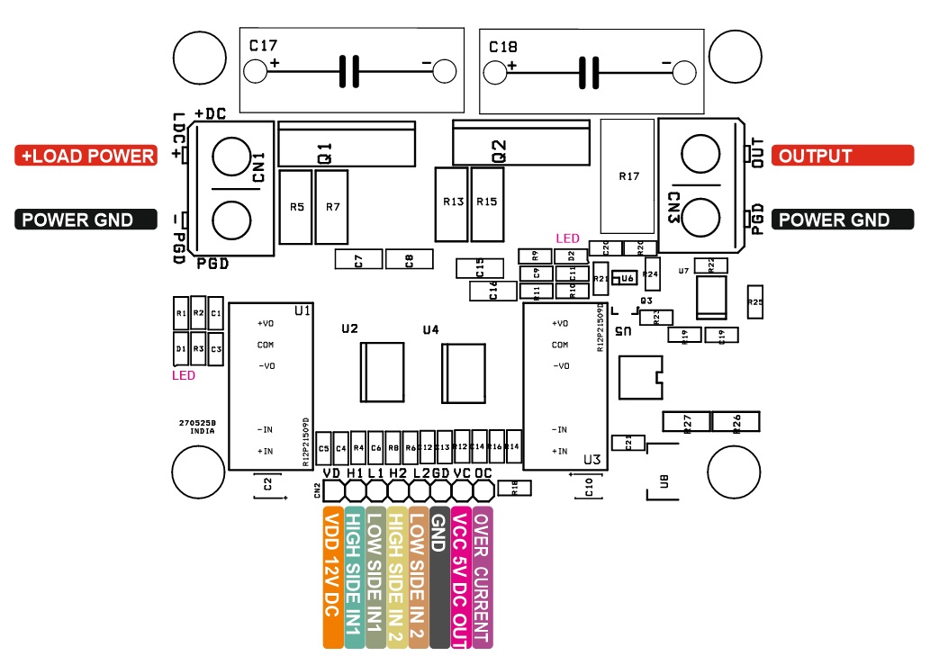
Connections
- CN1: Pin 1 = + Load Power, Pin 2 = -Load Power GND
- CN2: Pin 1 = VDD/12V DC, Pin 2 = High 1, Pin 3 = Low 1, Pin 4 = High 2, Pin 5 = Low 2, Pin 6 = GND Input Side, Pin 7 = VCC 5V Output, Pin 8 = Current Output
- CN3: Pin 1 = +Load, Pin 2 = Power GND
- D1: Upper Side IGBT Power LED
- D2: Lower Side IGBT Power LED
Schematic
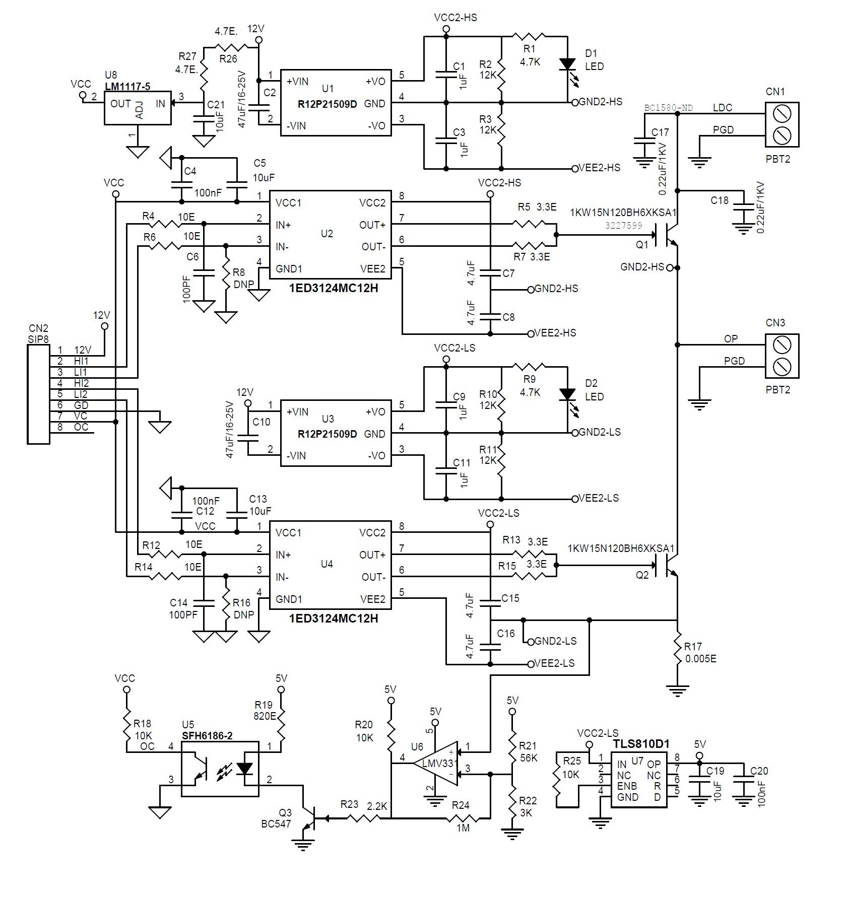
Parts List
| NO. | QNTY. | REF. | DESC. | MANUFACTURER | SUPPLIER | SUPPLIER PART NO |
|---|---|---|---|---|---|---|
| 1 | 2 | CN1,CN3 | 2 PIN SCREW TERMINAL PITCH 7.62MM | WURTH | DIGIKEY | 732-691254410002-ND |
| 2 | 1 | CN2 | 8 PIN MALE HEADER PITCH 2.54MM | WURTH | DIGIKEY | 732-5321-ND |
| 3 | 4 | C1,C3,C9,C11 | 1uF/35V CERAMIC SMD SIZE 0805 | YAGEO/MURATA | DIGIKEY | |
| 4 | 2 | C2,C10 | 47uF/16-25V CERAMIC SMD SIZE 1210 | YAGEO/MURATA | DIGIKEY | |
| 5 | 3 | C4,C12,C20 | 100nF/50V CERAMIC SMD SIZE 0805 | YAGEO/MURATA | DIGIKEY | |
| 6 | 4 | C5,C13,C19,C21 | 10uF/25V CERAMIC SMD SIZE 0805 | YAGEO/MURATA | DIGIKEY | |
| 7 | 2 | C6,C14 | 100PF/50V CERAMIC SMD SIZE 0805 | YAGEO/MURATA | DIGIKEY | |
| 8 | 4 | C7,C8,C15,C16 | 4.7uF/35V CERAMIC SMD SIZE 1206 | YAGEO/MURATA | DIGIKEY | |
| 9 | 2 | C17,C18 | 0.22uF/1KV | VISHAY | DIGIKEY | BC1580-ND |
| 10 | 2 | D1,D2 | LED RED SMD SIZE 0805 | OSRAM | DIGIKEY | 475-1278-1-ND |
| 11 | 2 | Q1,Q2 | IKW15N120BH6XKSA1 | INFINEON | DIGIKEY | 448-IKW15N120BH6XKSA1-ND |
| 12 | 1 | Q3 | BC547 SOT23-3 | NEXPERIA | DIGIKEY | 1727-2924-2-ND |
| 13 | 2 | R1,R9 | 4.7K 5% SMD SIZE 0805 | YAGEO/MURATA | DIGIKEY | |
| 14 | 4 | R2,R3,R10,R11 | 12K 5% SMD SIZE 0805 | YAGEO/MURATA | DIGIKEY | |
| 15 | 4 | R4,R6,R12,R14 | 10E 5% SMD SIZE 0805 | YAGEO/MURATA | DIGIKEY | |
| 16 | 4 | R5,R7,R13,R15 | 3.3E 5% SMD SIZE 2512 | YAGEO/MURATA | DIGIKEY | |
| 17 | 2 | R8,R16 | DNP | |||
| 18 | 1 | R17 | 0.005E/3W 1% SMD SIZE 2512 OR 4725 | VISHAY | DIGIKEY | WSRB-.005CT-ND |
| 19 | 3 | R18,R20,R25 | 10K 5% SMD SIZE 0805 | YAGEO/MURATA | DIGIKEY | |
| 20 | 1 | R19 | 820E 5% SMD SIZE 0805 | YAGEO/MURATA | DIGIKEY | |
| 21 | 1 | R21 | 56K 1% SMD SIZE 0805 | YAGEO/MURATA | DIGIKEY | |
| 22 | 1 | R22 | 3K 1% SMD SIZE 0805 | YAGEO/MURATA | DIGIKEY | |
| 23 | 1 | R23 | 2.2K 5% SMD SIZE 0805 | YAGEO/MURATA | DIGIKEY | |
| 24 | 1 | R24 | 1M 5% SMD SIZE 0805 | YAGEO/MURATA | DIGIKEY | |
| 25 | 2 | R26,R27 | 4.7E 5% SMD SIZE 1206 | YAGEO/MURATA | DIGIKEY | |
| 26 | 2 | U1,U3 | R12P21509D | RECOM POWER | DIGIKEY | 945-2800-ND |
| 27 | 2 | U2,U4 | 1ED3124MC12H | INFINEON | DIGIKEY | 448-1ED3124MC12HXUMA1CT-ND |
| 28 | 1 | U5 | SFH6186-2 | INFINEON | DIGIKEY | SFH6186-2-ND |
| 29 | 1 | U6 | LMV331 | ON SEMI | DIGIKEY | LMV331SQ3T2GOSCT-ND |
| 30 | 1 | U7 | TLS810D1 | INFINEON | DIGIKEY | TLS810D1EJV50XUMA1CT-ND |
| 31 | 1 | U8 | LM1117-5 | TI | DIGIKEY | LM1117MPX-5.0/NOPBCT-ND |
Connections
Application Diagram
Chip Block Diagram
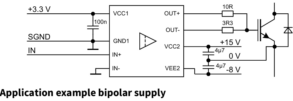
Bipolar Power Supply Example
Gerber View
Photos