LED VU Meter with LM3916
This project is a LED VU meter based on LM3916. Description LM3916 is a dedicated IC for VU LED meter.
This project is a LED VU meter based on LM3916.
Description
LM3916 is a dedicated IC for VU LED meter. Unlike LM3915 which have 3dB step between voltage levels, the LM3916 have nonlinear steps: -20, -10, -7, -5, -3, -1, 0, +1, +2, +3db, just like old school analog VU meters. I saw in YouTube an interesting commercial LED VU meter, which imitates the needle movement in analog VU meters and I thought I can make a similar one. All I needed I found in the datasheet of LM3916.
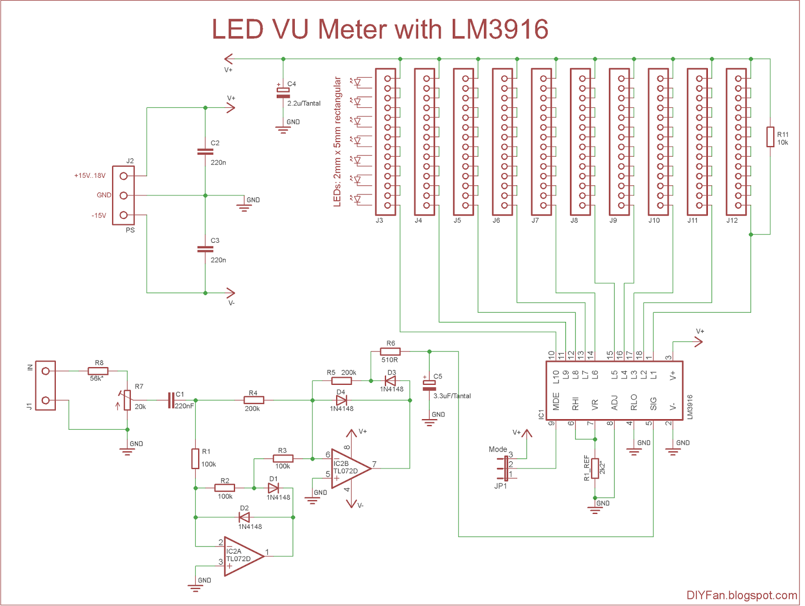
The LM3916 can be feed with AC signal without any rectification, but I wanted to implement a precision full wave rectification. I chose the schematic on page 13, fig.21 of the datasheet: “Precision Full-Wave Peak Detector”.
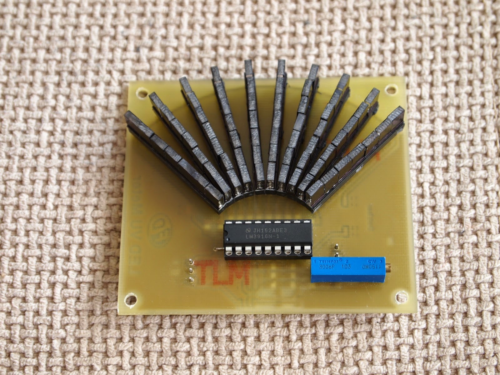
The LEDs are connected via sockets J3 to J12 (only one row LEDs is shown on the schematic) and I found that it’s cheaper to use a 28 pin IC sockets cut in half than regular 40 pin sockets. Of course LEDs can be soldered directly on the PCB.
The schematic needs bipolar power supply to work correctly, but the negative rail can be as low as -5V or even -3.3V. The positive rail must be bellow +25V and combined voltage of negative and positive rails must not exceed 36V. The minimum positive rail voltage depends on the voltage of the LEDs. For example if the LED have 1.9V forward voltage and we have 7 LEDs on one pin, then the minimum positive voltage will be 7*1.9V + 1.5V (drop voltage at LM3916) = 14.8V. The green LEDs usually have little higher forward voltage – 2.2V – 2.4V, so +18V will be sufficient in most cases.
The LEDs current is determined by R1_REF, and with 2.2k resistance it will be 5 – 6 mA.
The formula is Iled = 10 * (1.2V / R1_REF).
IC2 is connected as precision full wave rectifier and can be any general purpose dual opamp – TL072, TL082, LF353.
The output mode can be set with 3-pin jumper JP1. Shorting pins 1-2 will set the bar mode and shorting pins 2-3 will set the dot mode.
The max input voltage of the LM3916 is set to 1.2V, and with R8-R7 we can adjust the input level.
The color of the LEDs is your choice. I used green LEDs for negative levels, yellow for 0dB and red for positive levels. For this project I bought transparent rectangular LEDs, but they have two drawbacks. First – when one column lights up the adjacent columns also significantly lights up. My solution was to paint the sides of the LEDs with black marker. There also can be used a black tape around the entire collumn.
Second drawback is that because of the transparency, the LEDs emit light from one point, which is not very pleasant. The solution here was to rasp the top side of the LEDs with rough file, so the light to diffuse more even.
Schematic
even if that ic was “adressing” the leds correctly, how is this even supposed to work with all leds connected in serial
you dont even give a reference for the rectangular led arrays
Like moving needle, you dimmed.