Motorized Slide Potentiometer Driver
This motorized slide potentiometer is used in lighting and Audio/Video equipment or other similar application. It is a simple solution to control a motorized slide potentiometer using two tactile switches or a microcontroller interface.
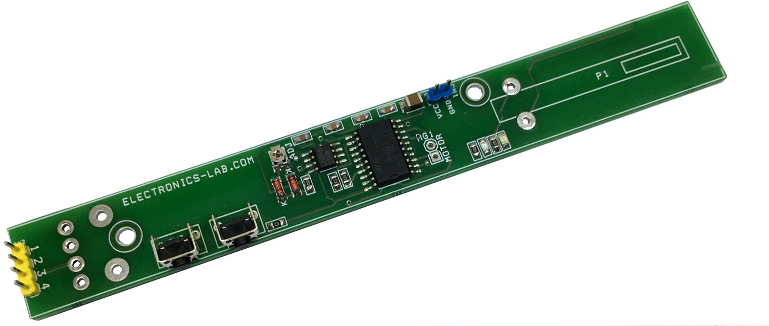
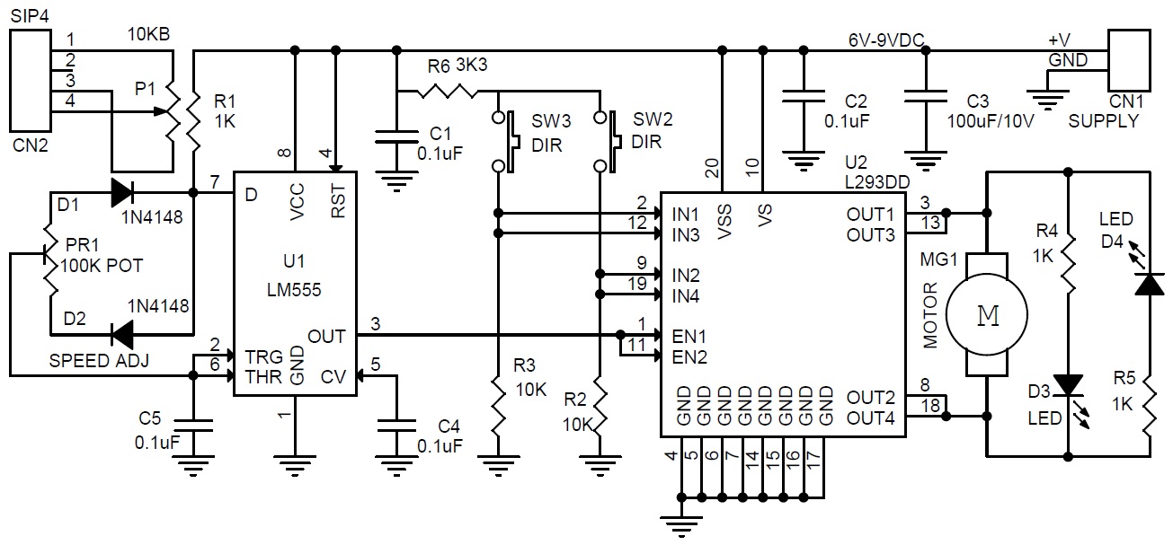
This motorized slide potentiometer is used in lighting and Audio/Video equipment or other similar application. It is a simple solution to control a motorized slide potentiometer using two tactile switches or a microcontroller interface. The project includes bidirectional motor driver L293DD H-Bridge chip, LM555 timer IC to generate the PWM pulse for speed control and two tactile switches to control the direction of the motor. Instead of two tactile switches, these pins can be interfaced with Arduino or microcontroller. SW2 and SW3 are used for CCW/CW motor control. PR1 trimmer potentiometer is provided to set the motor speed. Operating power supply of the project 6V to 9V DC. LED D3 and D4 Motor direction indicator. We have used a 10KB taper resistance potentiometer with a 100mm travel distance.
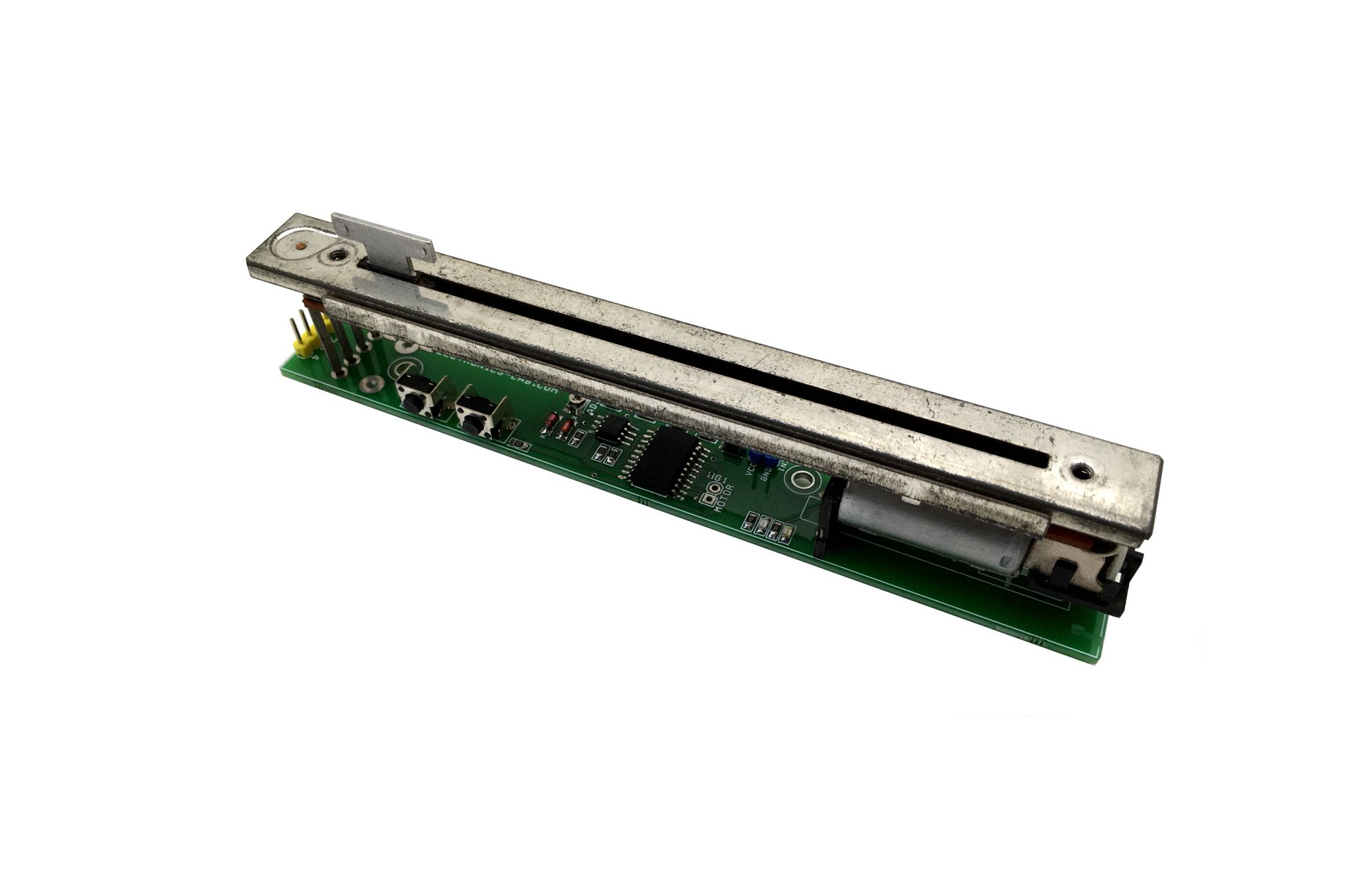
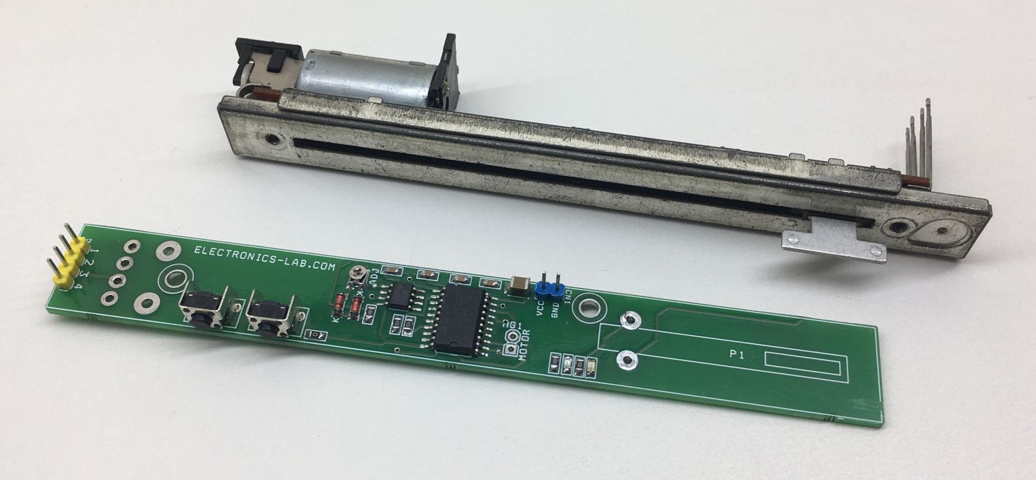
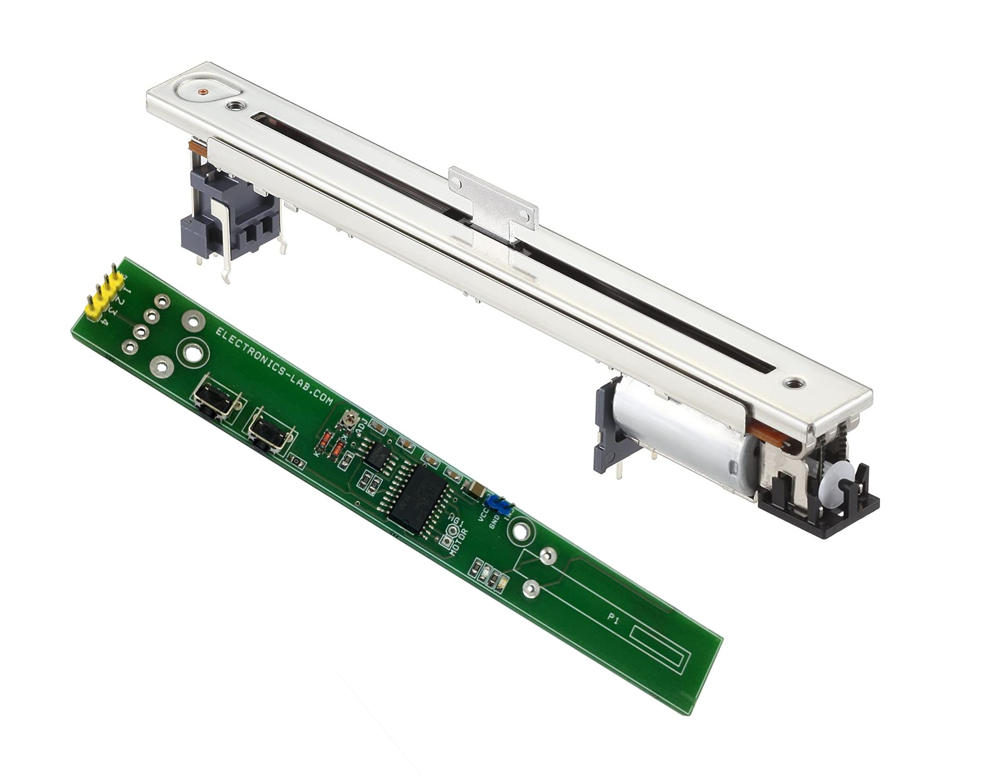
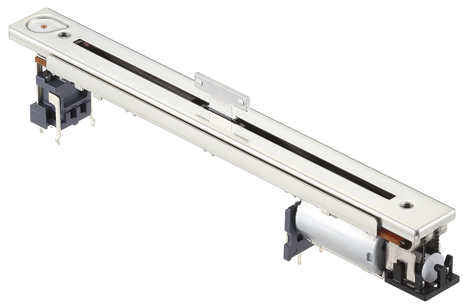
A motorized potentiometer is a slide pot which is has a timing belt driven by a small DC brushed motor and two-timing pulley. It is a single channel 10K Ohms B type resistance taper Pot.
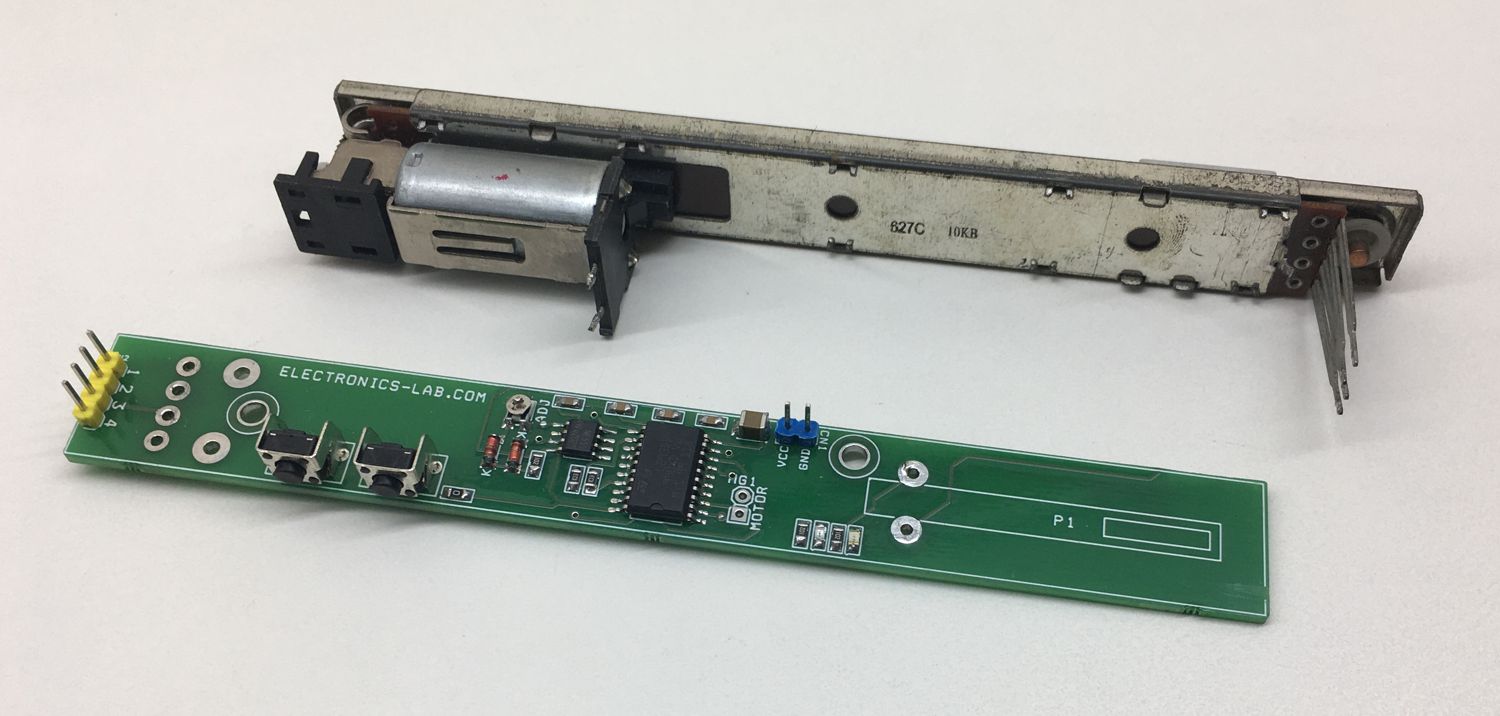
Motor Slide Potentiometer (ALPS ALPLINE) – Part number: RSA0N11M9A0J
Features
- Operating Supply 9V DC (6V to 9V)
- Current consumption 400mA Peak
- PWM Frequency Approx. 5Khz
- Duty Cycle 10 to 90%
- Motor Potentiometer Travel 100MM
- Potentiometer 10K Resistance B Type Taper (RSA0N11M9A0J)
- 2 X Motor Direction LED
- Trimmer Potentiometer for Motor speed adjust
- 2 X Tactile Switches Motor CW/CCW Direction Control
- PCB Dimensions 147.32 x 18.89 mm
Schematic
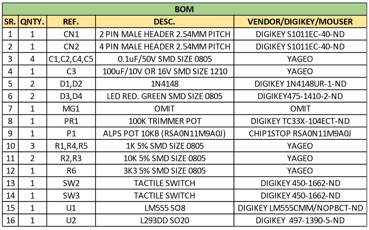
Parts List
Connections

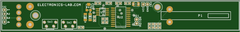
Gerber Views

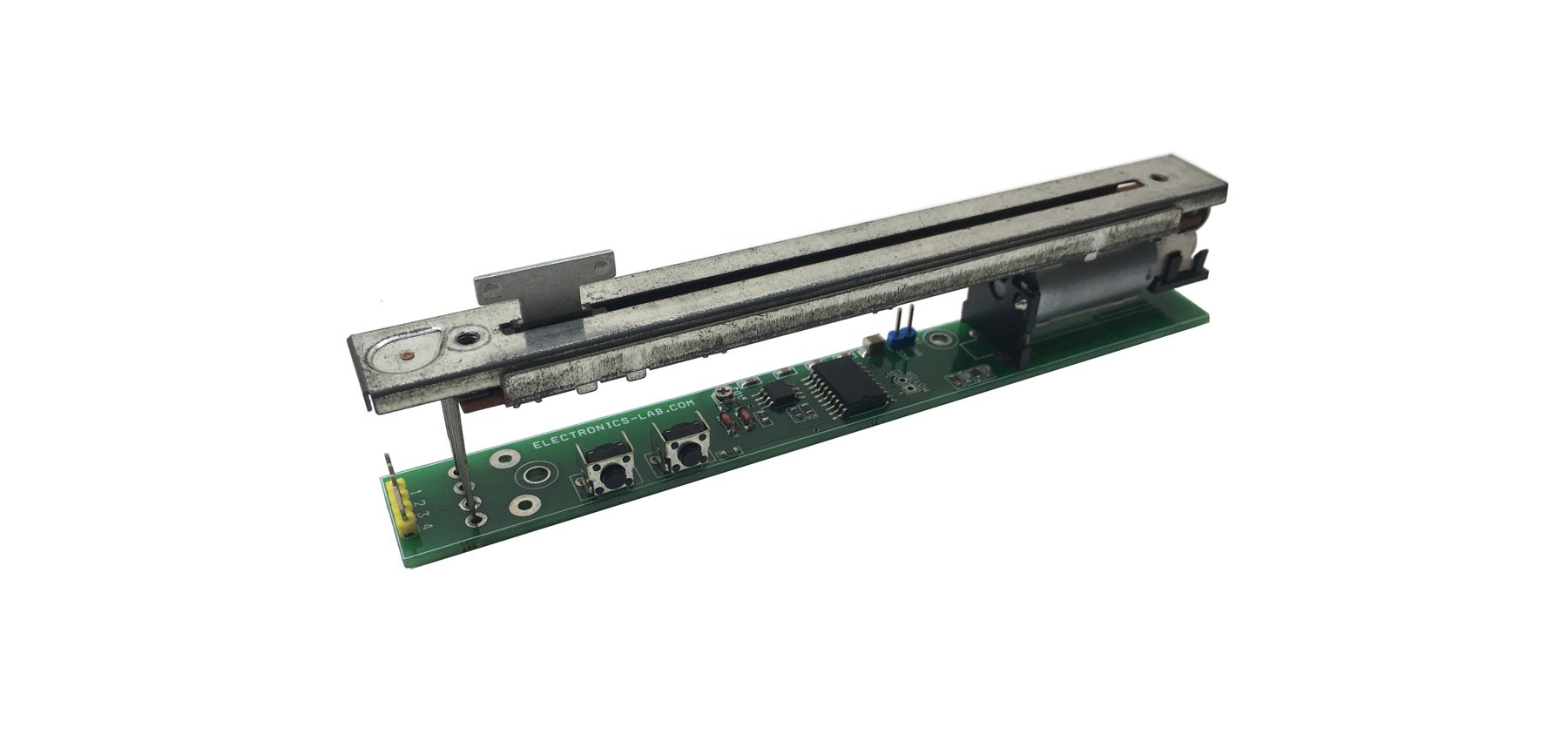
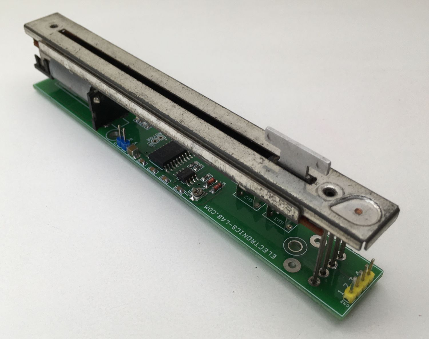
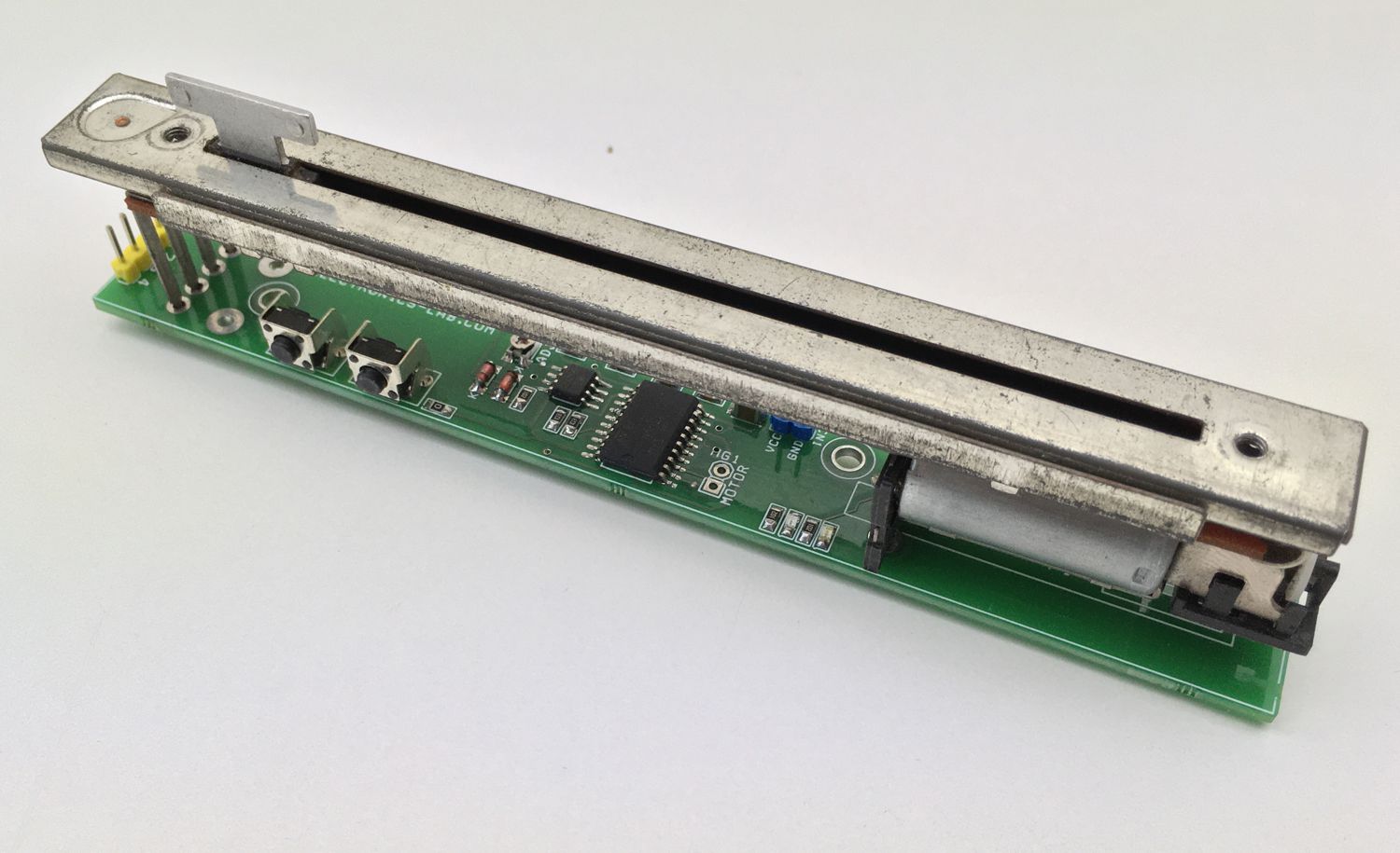
Photos