RS485 Light Sensor Interface Board
This ATmega328-based, Arduino-compatible board integrates an OPT101 light sensor and an SN65HVD485E transceiver to provide a complete, ready-to-use platform for developing RS485 network sensors with optional OLED display support.
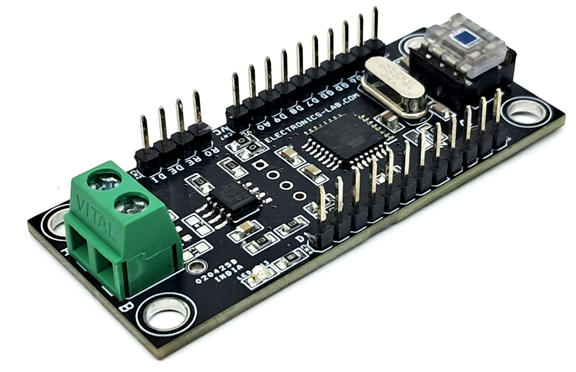
This Arduino-compatible hardware is primarily designed for RS485-based applications. It features an ATmega328 microcontroller, RS485 SN65HVD485E Half-Duplex RS-485 Transceiver chip, OPT101 light sensor, multiple I/O lines, and a provision for mounting a 0.96-inch OLED display.
A simple and practical example application is a light sensor system communicating over RS485. Screw terminals are provided for easy connection of the RS485 A and B twisted pair cables, while all other I/O lines are accessible through header connectors.
This board is ideal for developing light-sensing and other sensor-based RS485 communication projects.
SN65HVD485E Half-Duplex RS-485 Transceiver vs Arduino Pins
- RO= Arduino D10
- RE = Arduino D2
- DE = Arduino D3
- DI = Arduino D11
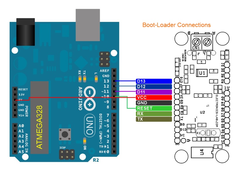
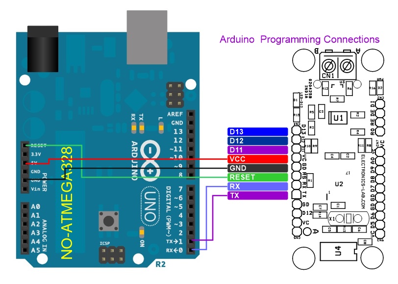
Arduino Programming
Features
- Supply 5V DC
- OPT101 Light Sensor on Board
- RS485 Communication (Half-Duplex)
- Screw Terminal for RS485 Connection
- RS485 Bus-pin ESD protection up to 15 kV
- RS485 Bus-open-failsafe receiver
- Glitch-free power-up and power-down bus inputs and outputs
- Multiple I/O Lines Available for Interface
- On Board Power LED
- On Borad Function LED Connected to D13
- On Board Optional 0.96 OLED Display
- On Board Optional RF433 MHz RF Module
- 4 x 4 mm Mounting Holes
- PCB Dimensions 62.55 x 26.51 mm
SN65HVD485E Half-Duplex RS-485 Transceiver
The SN65HVD485E device is a half-duplex transceiver designed for RS-485 data bus networks. Powered by a 5-V supply, it is fully compliant with the TIA/EIA-485A standard. This device is suitable for data transmission up to 10 Mbps over long twisted pair cables and is designed to operate with very low supply current, typically less than 2 mA, exclusive of the load. When the device is in the inactive shutdown mode, the supply current drops below 1 mA. The wide common-mode range and high ESD protection levels of this device make it suitable for demanding applications such as: electrical inverters, status/command signals across telecom racks, cabled chassis interconnects, and industrial automation networks where noise tolerance is essential. The SN65HVD485E device matches the industry-standard footprint of the SN75176 device. Power-on reset circuits keep the outputs in a high-impedance state until the supply voltage has stabilized. A thermal shutdown function protects the device from damage due to system-fault conditions.
Device Functional Modes (RS485)
When the driver enable pin (DE) is logic high, the differential outputs A and B follow the logic states at data input D. A logic high at D causes A to turn high and B to turn low. In this case, the differential output voltage defined as VOD = VA – VB is positive. When D is low, the output states reverse, B turns high, A is low, and VOD is negative. When DE is low, both outputs turn high impedance. In this condition, the logic state at D is irrelevant. The DE pin has an internal pulldown resistor to ground; thus, when left open, the driver is disabled (high impedance) by default. The D pin has an internal pullup resistor to VCC; thus, when left open while the driver is enabled, output A turns high and B turns low.
When the receiver enable pin (RE) is logic low, the receiver is enabled. When the differential input voltage defined as VID = VA – VB is positive and higher than the positive input threshold (VIT+) the receiver output (R) turns high. When VID is negative and lower than the negative input threshold (VIT–), the receiver output (R) turns low. If VID is between VIT+ and VIT–, the output is indeterminate. When V RE is logic high or left open, the receiver output is high impedance and the magnitude and polarity of VID are irrelevant. Internal biasing of the receiver inputs causes the output to go failsafe high when the transceiver is disconnected from the bus (open-circuit), the bus lines are shorted (short-circuit), or the bus is not actively driven (idle bus)
The OPT101 is a monolithic photodiode with on-chip transimpedance amplifier. The integrated combination of photodiode and transimpedance amplifier on a single chip eliminates the problems commonly encountered in discrete designs, such as leakage current errors, noise pick-up, and gain peaking as a result of stray capacitance. Output voltage increases linearly with light intensity. The amplifier is designed for single or dual power-supply operation. The 0.09 inch × 0.09-inch (2.29 mm × 2.29 mm) photodiode operates in the photoconductive mode for excellent linearity and low dark current.
The OPT101 voltage output is the product of the photodiode current times the feedback resistor, (IDRF), plus a pedestal voltage, VB, of approximately 7.5 mV introduced for single-supply operation. Output is 7.5 mV dc with no light, and increases with increasing illumination. Photodiode current, ID, is proportional to the radiant power, or flux, (in watts) falling on the photodiode. At a wavelength of 650 nm (visible red) the photodiode responsivity, RI, is approximately 0.45 A/W.
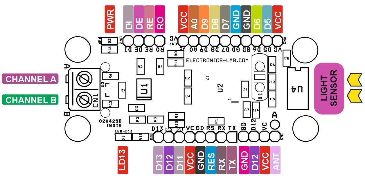
Connections
- CN1: Pin 1 = RS485 Channel B, Pin 2 = RS485 Channel A
- CN2 RS485 Chips I/O: Pin 1 = RO, Pin 2 = RE, Pin 3 = DE, Pin 4 = DI
- CN3: OLED Display Optional
- CN4 Programming Connector: Pin 1 = TX, Pin 2 = RX, Pin 3 = Reset, Pin 4 = GND, Pin 5 = VCC, Pin 6 = D11, Pin 7 = D12, Pin 8 = D13
- CN5: Optional RF 433 MHz RF Module
- CN6: Pin 1 = VCC, Pin 2 = D5, Pin 3 = D6, Pin 4 = GND
- CN7: Pin 1 = VCC, Pin 2 = A0, Pin 3 = D9, Pin 4 = D8, Pin 5 = D7, Pin 6 = GND
- CN8: Pin 1 = VCC, Pin 2 = D4, Pin 3 = A3, Pin 4 = A2, Pin 5 = NC, Pin 6 = GND
- D1: LED Connected to D13
- D2: Power LED
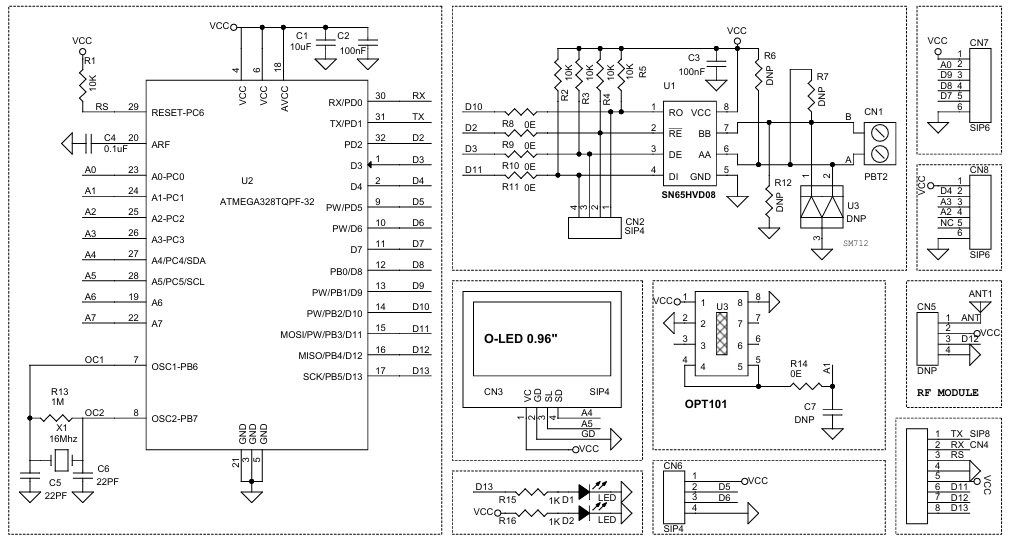
Schematic
Parts List
| NO. | QNTY. | REF. | DESC. | MANUFACTURER | SUPPLIER | SUPPLIER PART NO |
|---|---|---|---|---|---|---|
| 1 | 1 | ANT1 | DNP/OPTIONAL | |||
| 2 | 1 | CN1 | 2 PIN SCREW TERMINAL PITCH 5.08MM | PHOENIX | DIGIKEY | 277-1247-ND |
| 3 | 3 | CN2,CN3,CN6 | 4 PIN MALE HEADER PITCH 2.54MM | WURTH | DIGIKEY | 732-5317-ND |
| 4 | 1 | CN4 | 8 PIN MALE HEADER PITCH 2.54MM | WURTH | DIGIKEY | 732-5321-ND |
| 5 | 6 | U3,CN5,R6,R7,C7,R12 | DNP | |||
| 6 | 2 | CN7 | 6PIN MALE HEADER PITCH 2.54MM | WURTH | DIGIKEY | 732-5319-ND |
| 7 | 1 | C1 | 10uF/10V CERAMIC SMD SIZE 0805 | YAGEO/MURATA | DIGIKEY | |
| 8 | 3 | C2,C3,C4 | 100nF/50V CERAMIC SMD SIZE 0805 | YAGEO/MURATA | DIGIKEY | |
| 9 | 2 | C5,C6 | 22PF/50V CERAMIC SMD SIZE 0805 | YAGEO/MURATA | DIGIKEY | |
| 10 | 2 | D1,D2 | LED RED SMD SIZE 0805 | OSRAM | DIGIKEY | 475-1278-1-ND |
| 11 | 5 | R1,R2,R3,R4,R5 | 10K 5% SMD SIZE 0805 | YAGEO/MURATA | DIGIKEY | |
| 12 | 5 | R8,R9,R10,R11,R14 | 0E 5% SMD SIZE 0805 | YAGEO/MURATA | DIGIKEY | |
| 13 | 1 | R13 | 1M 5% SMD SIZE 0805 | YAGEO/MURATA | DIGIKEY | |
| 14 | 2 | R15,R16 | 1K 5% SMD SIZE 0805 | YAGEO/MURATA | DIGIKEY | |
| 15 | 1 | U1 | SN65HVD08 SOIC | TI | DIGIKEY | 296-39173-1-ND |
| 16 | 1 | U2 | ATMEGA328TQPF-32 | MICROCHIP | DIGIKEY | ATMEGA328PB-AURCT-ND |
| 17 | 1 | U3 | OPT101 DIP8 | TI | DIGIKEY | OPT101P-J-ND |
| 18 | 1 | X1 | 16Mhz | ECS INC | DIGIKEY | X1103-ND |
Connections
Gerber View
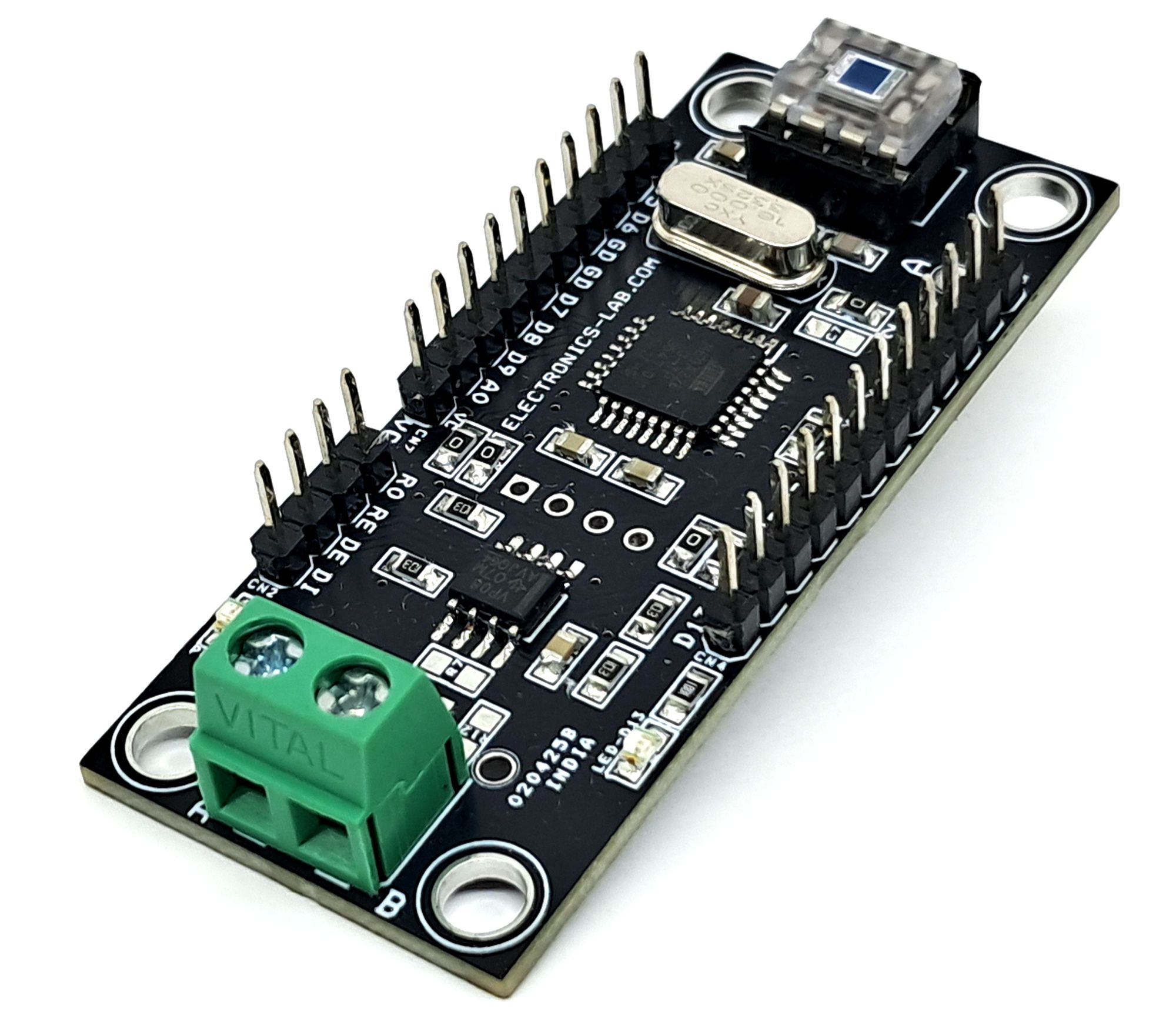
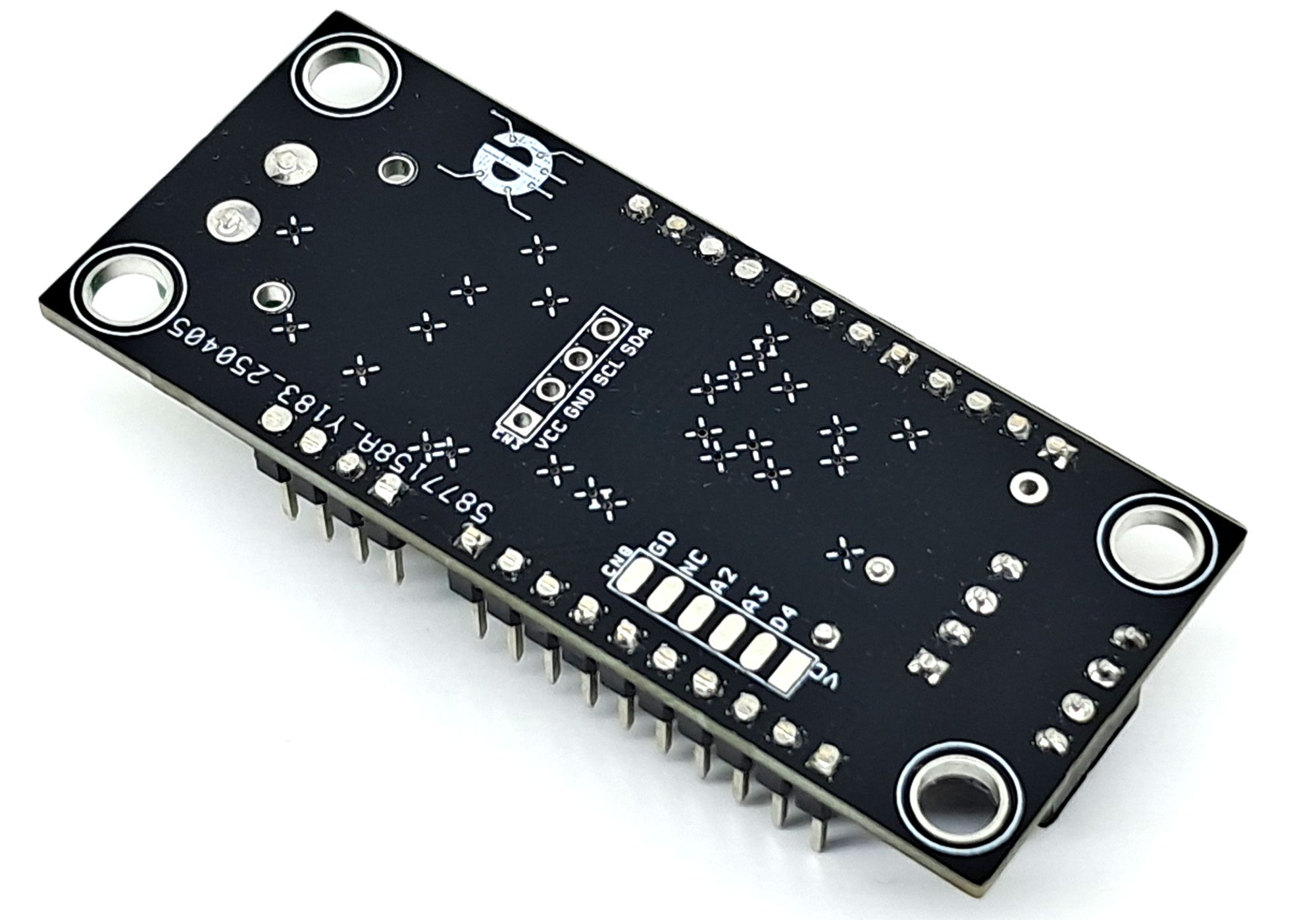
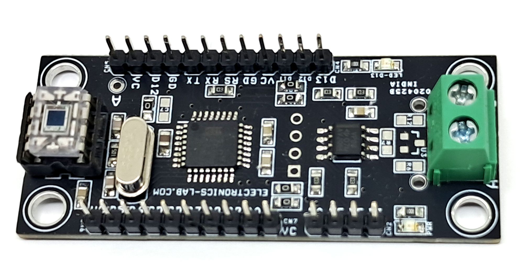
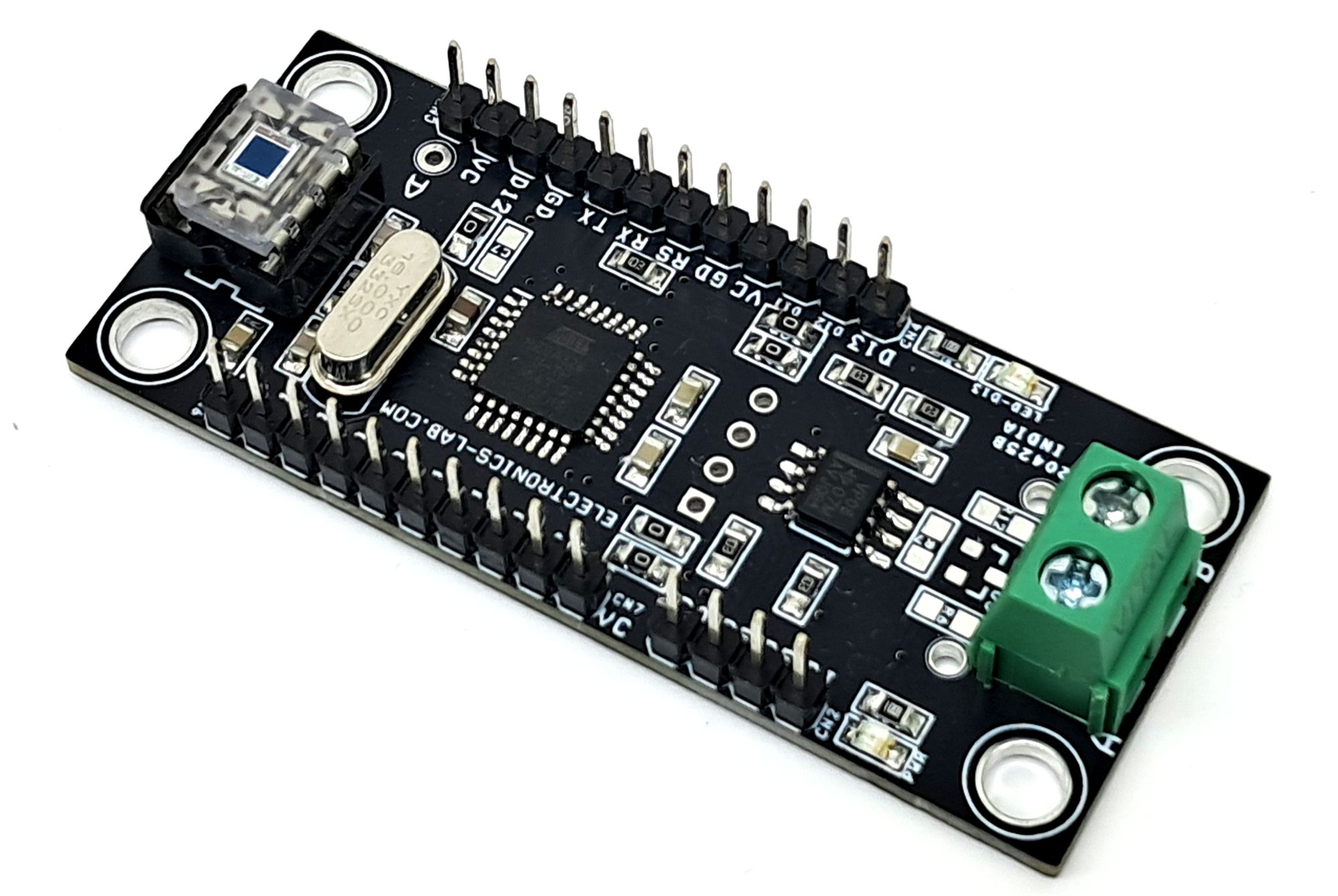
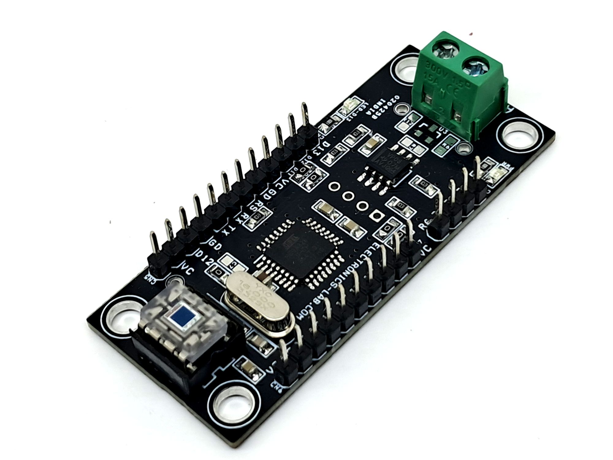
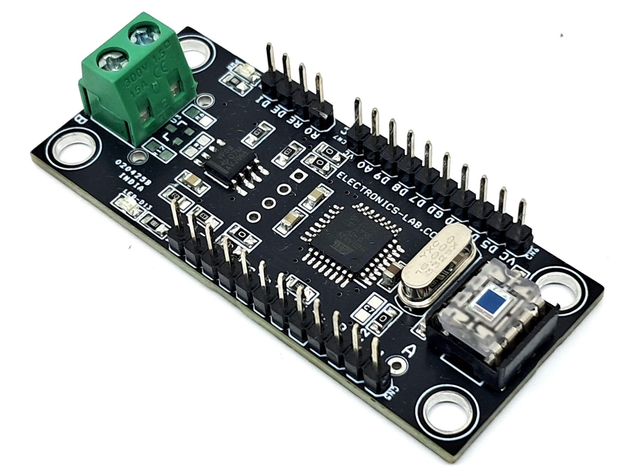
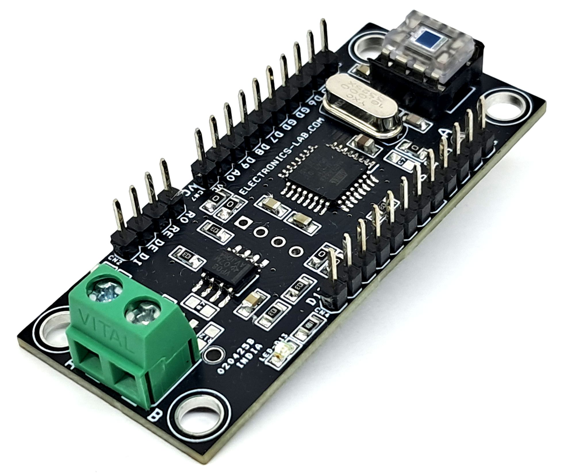
Photos
Thank you