Using a 20×4 I2C Character LCD display with Arduino Uno
On previous tutorials on our website, we have covered the use of several displays, LCDs, and TFTs, with diverse Arduino boards. From Nokia 5110 LCD display to different types of OLEDs, the reason for the tutorials has been to ensure that, as a reader, you know how to use many of the most popular displays so this help you make the best choice when trying to select the perfect display for your project.
On previous tutorials on our website, we have covered the use of several displays, LCDs, and TFTs, with diverse Arduino boards. From Nokia 5110 LCD display to different types of OLEDs, the reason for the tutorials has been to ensure that, as a reader, you know how to use many of the most popular displays so this help you make the best choice when trying to select the perfect display for your project. For today’s tutorial, we will continue in that line and examine how to use the 20×4 I2C Character LCD Display with Arduino.
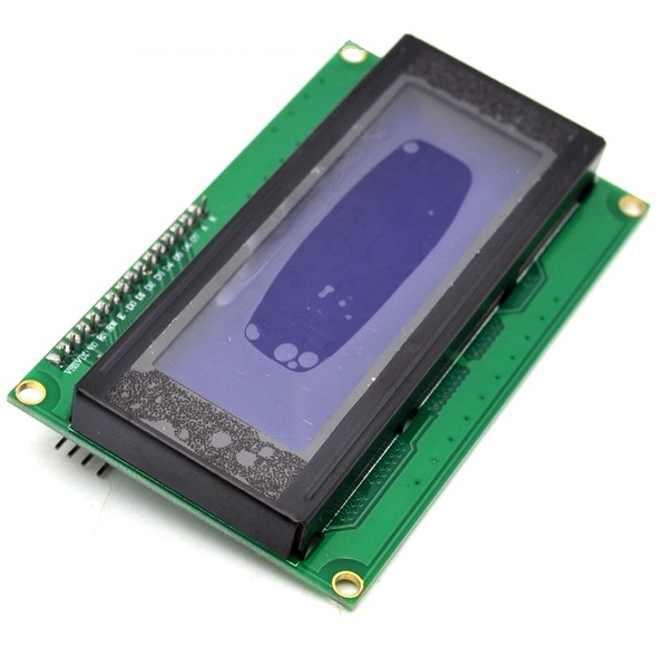
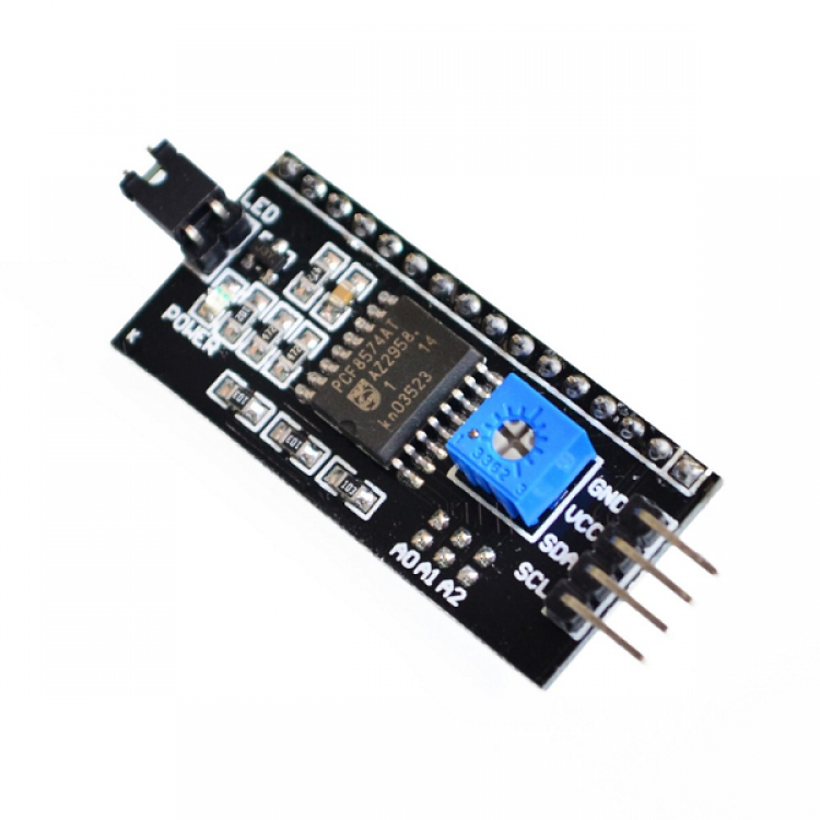
The 20×4 LCD display is essentially a bigger (increased number of rows and columns) version of the 16×2 LCD display with which we have built several projects. The display has room to display 20 columns of characters on 4 rows which makes it perfect for displaying a large amount of text without scrolling. Each of the columns has a resolution of 5×8 pixels which ensures its visibility from a substantial distance. Asides its size, the interesting thing about this version of the display being used for today’s tutorial is the fact that it communicates via I2C, which means we will only require 2 wires asides GND and VCC to connect the display to the Arduino. This is possible via the Parallel to I2C module coupled to the display as shown in picture below. The I2C module can also be bought individually, and coupled to the 16 pins version of the display.
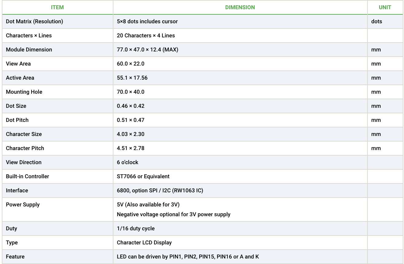
A summary of some of the features of the LCD display is provided in the table below.
To demonstrate how to use this display, we will build a real-time clock which will display date and time on the LCD. To generate and keep track of date and time, we will use the DS3231 Real time clock. We covered the use of the DS3231 RTC module in the tutorial on DS3231 based Real-time Clock, you can check it out to learn more about its use with the Arduino.
Required Components
The following components are required for this project.
The exact component used for this tutorial can be bought via the links attached and the power bank is only required to run the Arduino when not connected to the computer. You can replace this with a 9V battery and a center-positive power jack.
Schematics
Since the display and the real-time clock are both I2C devices, they will be connected to the same pins on the Arduino. For the Arduino Uno, the I2C pins are located on Pin A5 (SCL) and A4 (SDA). This may differ on any of the other Arduino boards. Connect the components as shown in the schematics below;
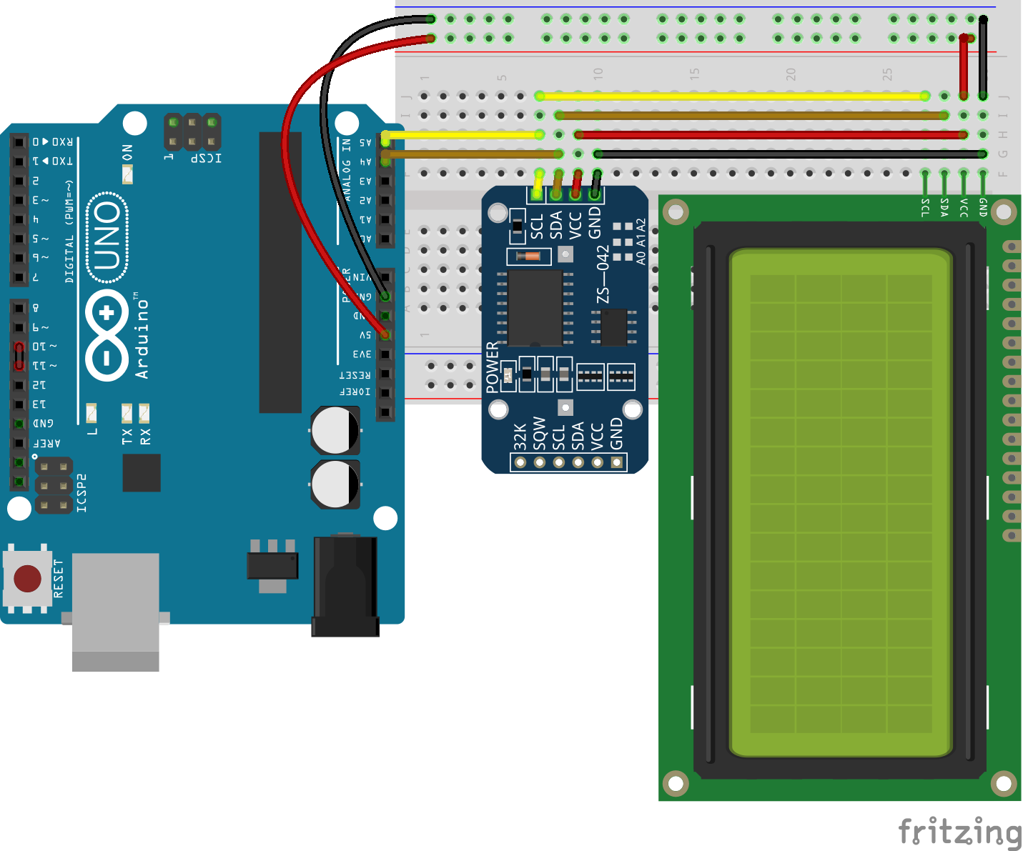
To make the connections, even more easier to follow, the pin connections of the components is described below.
Arduino – LCD
GND - GND
5v - VCC
A4 - SDA
A5 - SCL
The DS3231 is connected in the same way;
Arduino – DS3231
GND - GND
5v - VCC
A4 - SDA
A5 - SCL
With the connections all done, we can now proceed to write the code for the project.
Code
To write the code for this project, we will use three main libraries; the DS1307 Library to easily interface with the DS3231 module, the liquid crystal I2C library to easily interface with the LCD display, and the Wire library for I2C communication. While the Wire library comes built into the Arduino IDE, the other two libraries can be downloaded and installed via the links attached to them.
As mentioned during the introduction, our task for today is to obtain time and date information from the RTC module and display on the LCD. As usual, I will do a breakdown of the code and try to explain some of the concepts within it that may be difficult to understand.
We start the code by including the libraries that will be used. After which we create an object of the Liquid crystal library, with the I2C address of the LCD as an argument. The I2C address can be obtained from the seller or as described in our tutorial on using the 16×2 LCD display to ESP32.
#include <Wire.h>
#include <LiquidCrystal_I2C.h>
#include <DS1307RTC.h>

LiquidCrystal_I2C lcd(0x27, 2, 1, 0, 4, 5, 6, 7, 3, POSITIVE);  // Set the LCD I2C address
Next, we create a set of variables which comprises of byte arrays that represent custom characters to be created and displayed. The custom characters are usually 5pixels in width and 8 pixels in height, representing each box in the rows or columns of the LCD. The byte array represents which pixels of the box to be turned on or off.
byte verticalLine[8] = {
  B00100,
  B00100,
  B00100,
  B00100,
  B00100,
  B00100,
  B00100,
  B00100
};

byte char2[8] = {
  B00000,
  B00000,
  B00000,
  B11100,
  B00100,
  B00100,
  B00100,
  B00100
};

byte char1[8] = {
  0b00000,
  0b00000,
  0b00000,
  0b00111,
  0b00100,
  0b00100,
  0b00100,
  0b00100
};

byte char3[8] = {
  0b00100,
  0b00100,
  0b00100,
  0b00111,
  0b00000,
  0b00000,
  0b00000,
  0b00000
};

byte char4[8] = {
  0b00100,
  0b00100,
  0b00100,
  0b11100,
  0b00000,
  0b00000,
  0b00000,
  0b00000
};
Next, we write the void setup function and start by initializing the library using the lcd.begin() function, with the first argument representing the number of columns, and the second argument representing the number of rows. After this, the CreateCustomCharacters() function is called to convert the char variables created above into characters that can be displayed on the LCD. One of the characters created is then used to create a UI/frame which is displayed using the printFrame() function.
void setup()
{
  lcd.begin(20,4);

  createCustomCharacters();

  printFrame();
}
With that done, we proceed to the voidloop() function.
The idea behind the voidloop function is simple. We create a variable “tm” to hold time elements and then call the RTC.read() function such that its response is stored in tm. This is all done within an if statement which prints the time and date value stored in tm, if a response is received from the rtc. If a response is not received, the else statement is executed.
void loop()
{
   tmElements_t tm;

  if (RTC.read(tm)) {
    printDate(5,1,tm);
    printTime(6,2,tm);

  } else {
    if (RTC.chipPresent()) {

    } else {

    }
    delay(9000);
  }
To make the code easy to read and portable, this was all done with functions.
The first function is the printTime() which breaks down the time data stored in the “tm” variable to extract seconds, minutes and hour values. These values are then displayed on the LCD using the lcd.print() function.
void printTime(int character,int line, tmElements_t tm)
{
  String seconds,minutes;
  lcd.setCursor(character,line);
  lcd.print(tm.Hour);
  lcd.print(":");
  if(tm.Minute<10)
  {
    minutes = "0"+String(tm.Minute);
    lcd.print(minutes);
  }else
  {
    lcd.print(tm.Minute);
  }
  lcd.print(":");
  if(tm.Second<10)
  {
    seconds = "0"+String(tm.Second);
    lcd.print(seconds);
  }else
  {
    lcd.print(tm.Second);
  }
}
The printDate function is similar to the printTime function. It extracts date information from the variable tm and uses the lcd.print() function to display it.
void printDate(int character,int line, tmElements_t tm)
{
  lcd.setCursor(character,line);
  lcd.print(tm.Month);
  lcd.print("/");
  lcd.print(tm.Day);
  lcd.print("/");
  lcd.print(tmYearToCalendar(tm.Year));
}
Other functions include the createCustomCharacters() and the printFrame() functions. The createCustomCharacters() function, as the name implies, is used to create custom characters using byte arrays. The function takes two arguments; the character number, and the variable to in which the byte array for that character is stored. Only 7 characters can be created at once as such the character number is usually between 1 and 7.
void createCustomCharacters()
{
  lcd.createChar(0, verticalLine);
  lcd.createChar(1, char1);
  lcd.createChar(2, char2);
  lcd.createChar(3, char3);
  lcd.createChar(4, char4);
}
The printFrame() function, on the other hand, was used to create a sort of user interface for the project. it makes use of the characters created above. Each of the custom characters created is displayed using the lcd.write(byte(x)) function with x being the character number of the character to be displayed. The characters are positioned on the LCD using the lcd.setCursor() function which takes numbers representing the column and row on which the character is to be displayed, as arguments.
void printFrame()
{
  lcd.setCursor(1,0);
  lcd.print("------------------");
  lcd.setCursor(1,3);
  lcd.print("------------------");
  lcd.setCursor(0,1);
  lcd.write(byte(0));
  lcd.setCursor(0,2);
  lcd.write(byte(0));
  lcd.setCursor(19,1);
  lcd.write(byte(0));
  lcd.setCursor(19,2);
  lcd.write(byte(0));
  lcd.setCursor(0,0);
  lcd.write(byte(1));
  lcd.setCursor(19,0);
  lcd.write(byte(2));
  lcd.setCursor(0,3);
  lcd.write(byte(3));
  lcd.setCursor(19,3);
  lcd.write(byte(4));
}
The complete code for the project is available below and also attached under the download section
#include <Wire.h>
#include <LiquidCrystal_I2C.h>
#include <DS1307RTC.h>

LiquidCrystal_I2C lcd(0x27, 2, 1, 0, 4, 5, 6, 7, 3, POSITIVE);  // Set the LCD I2C address

byte verticalLine[8] = {
  B00100,
  B00100,
  B00100,
  B00100,
  B00100,
  B00100,
  B00100,
  B00100
};

byte char2[8] = {
  B00000,
  B00000,
  B00000,
  B11100,
  B00100,
  B00100,
  B00100,
  B00100
};

byte char1[8] = {
  0b00000,
  0b00000,
  0b00000,
  0b00111,
  0b00100,
  0b00100,
  0b00100,
  0b00100
};

byte char3[8] = {
  0b00100,
  0b00100,
  0b00100,
  0b00111,
  0b00000,
  0b00000,
  0b00000,
  0b00000
};

byte char4[8] = {
  0b00100,
  0b00100,
  0b00100,
  0b11100,
  0b00000,
  0b00000,
  0b00000,
  0b00000
};

void setup()
{
  lcd.begin(20,4);

  createCustomCharacters();

  printFrame();
}

void loop()
{
   tmElements_t tm;

  if (RTC.read(tm)) {
    printDate(5,1,tm);
    printTime(6,2,tm);

  } else {
    if (RTC.chipPresent()) {

    } else {

    }
    delay(9000);
  }
  delay(1000);
}

void printTime(int character,int line, tmElements_t tm)
{
  String seconds,minutes;
  lcd.setCursor(character,line);
  lcd.print(tm.Hour);
  lcd.print(":");
  if(tm.Minute<10)
  {
    minutes = "0"+String(tm.Minute);
    lcd.print(minutes);
  }else
  {
    lcd.print(tm.Minute);
  }
  lcd.print(":");
  if(tm.Second<10)
  {
    seconds = "0"+String(tm.Second);
    lcd.print(seconds);
  }else
  {
    lcd.print(tm.Second);
  }
}

void printDate(int character,int line, tmElements_t tm)
{
  lcd.setCursor(character,line);
  lcd.print(tm.Month);
  lcd.print("/");
  lcd.print(tm.Day);
  lcd.print("/");
  lcd.print(tmYearToCalendar(tm.Year));
}

void printFrame()
{
  lcd.setCursor(1,0);
  lcd.print("------------------");
  lcd.setCursor(1,3);
  lcd.print("------------------");
  lcd.setCursor(0,1);
  lcd.write(byte(0));
  lcd.setCursor(0,2);
  lcd.write(byte(0));
  lcd.setCursor(19,1);
  lcd.write(byte(0));
  lcd.setCursor(19,2);
  lcd.write(byte(0));
  lcd.setCursor(0,0);
  lcd.write(byte(1));
  lcd.setCursor(19,0);
  lcd.write(byte(2));
  lcd.setCursor(0,3);
  lcd.write(byte(3));
  lcd.setCursor(19,3);
  lcd.write(byte(4));
}

void createCustomCharacters()
{
  lcd.createChar(0, verticalLine);
  lcd.createChar(1, char1);
  lcd.createChar(2, char2);
  lcd.createChar(3, char3);
  lcd.createChar(4, char4);
}
Demo
As usual, go over the schematics to be sure everything is connected as it should be, then connect the Arduino board to your PC and upload the code to it. Ensure all the libraries have been installed to avoid errors.
With the upload done, you should see the time and date is displayed on the LCD as shown in the image below.
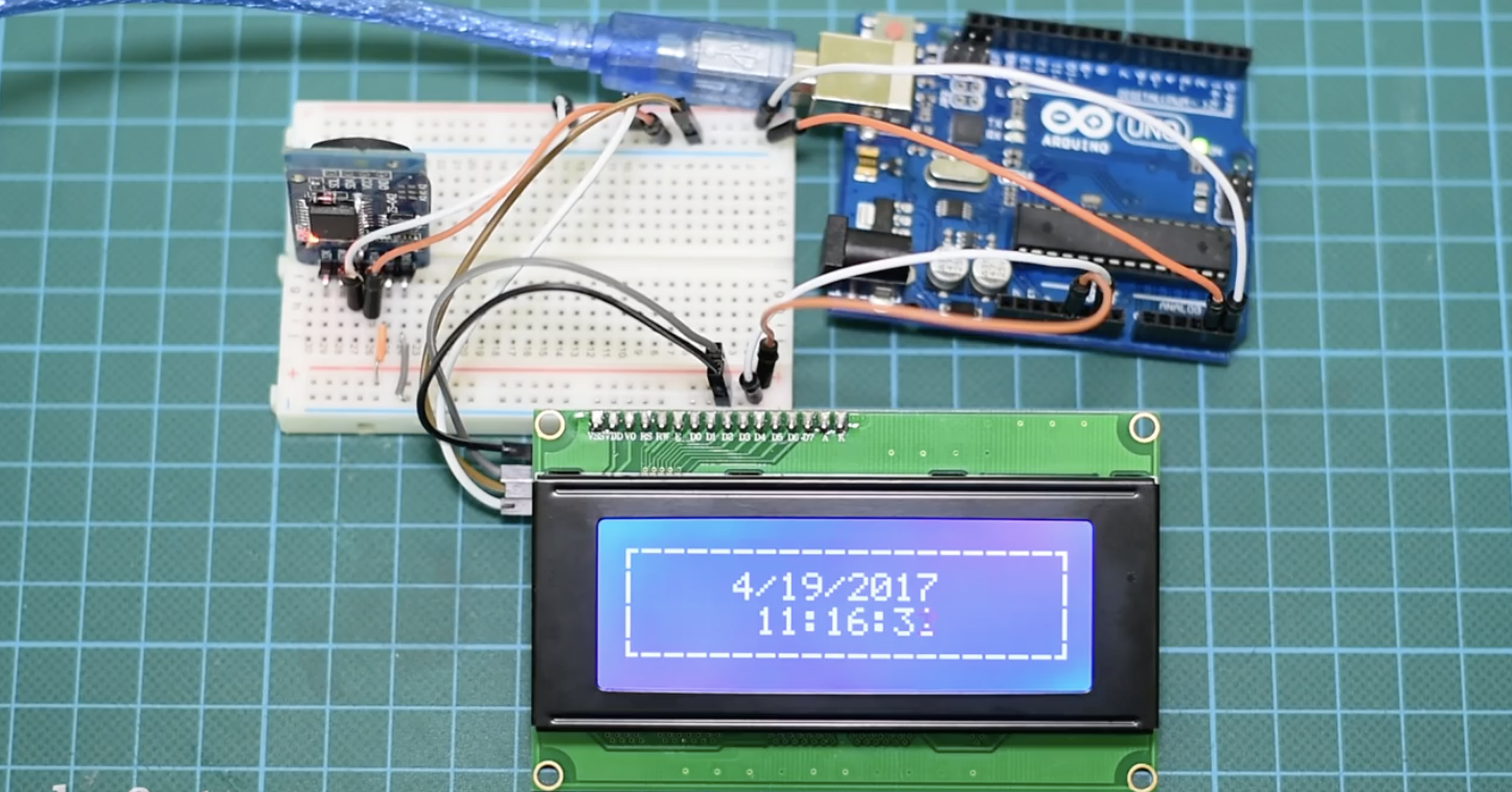
Different projects, come with different screen requirements. If you need to display a large amount of information and the size is not a constraint, the 20×4 I2C display is definitely one of the options you should consider.
That’s it for today’s project guys, thanks for reading along. Feel free to reach me via the comment section with any question about the project.
The video version of this tutorial is available on youtube.
getting the POSITIVE variable not defined
Arduino: 1.8.12 (Windows 10), Board: “Arduino Uno”
l_cd_20x4:4:53: error: ‘POSITIVE’ was not declared in this scope
LiquidCrystal_I2C lcd(0x27, 2, 1, 0, 4, 5, 6, 7, 3, POSITIVE); // Set the LCD I2C address
^~~~~~~~
C:\Users\mgjim\OneDrive\Desktop\l_cd_20x4\l_cd_20x4.ino: In function ‘void setup()’:
l_cd_20x4:60:17: error: no matching function for call to ‘LiquidCrystal_I2C::begin(int, int)’
lcd.begin(20,4);
^
In file included from C:\Users\mgjim\OneDrive\Desktop\l_cd_20x4\l_cd_20x4.ino:2:0:
C:\Users\mgjim\OneDrive\Documents\Arduino\libraries\LiquidCrystal_I2C/LiquidCrystal_I2C.h:76:7: note: candidate: void LiquidCrystal_I2C::begin()
void begin();
^~~~~
C:\Users\mgjim\OneDrive\Documents\Arduino\libraries\LiquidCrystal_I2C/LiquidCrystal_I2C.h:76:7: note: candidate expects 0 arguments, 2 provided
l_cd_20x4:62:3: error: ‘createCustomCharacters’ was not declared in this scope
createCustomCharacters();
^~~~~~~~~~~~~~~~~~~~~~
l_cd_20x4:64:3: error: ‘printFrame’ was not declared in this scope
printFrame();
^~~~~~~~~~
C:\Users\mgjim\OneDrive\Desktop\l_cd_20x4\l_cd_20x4.ino:64:3: note: suggested alternative: ‘Printable’
printFrame();
^~~~~~~~~~
Printable
C:\Users\mgjim\OneDrive\Desktop\l_cd_20x4\l_cd_20x4.ino: In function ‘void loop()’:
l_cd_20x4:72:5: error: ‘printDate’ was not declared in this scope
printDate(5,1,tm);
^~~~~~~~~
C:\Users\mgjim\OneDrive\Desktop\l_cd_20x4\l_cd_20x4.ino:72:5: note: suggested alternative: ‘Printable’
printDate(5,1,tm);
^~~~~~~~~
Printable
l_cd_20x4:73:5: error: ‘printTime’ was not declared in this scope
printTime(6,2,tm);
^~~~~~~~~
C:\Users\mgjim\OneDrive\Desktop\l_cd_20x4\l_cd_20x4.ino:73:5: note: suggested alternative: ‘breakTime’
printTime(6,2,tm);
^~~~~~~~~
breakTime
l_cd_20x4:85:1: error: a function-definition is not allowed here before ‘{‘ token
{
^
l_cd_20x4:111:1: error: a function-definition is not allowed here before ‘{‘ token
{
^
l_cd_20x4:122:1: error: a function-definition is not allowed here before ‘{‘ token
{
^
l_cd_20x4:132:1: error: a function-definition is not allowed here before ‘{‘ token
{
^
l_cd_20x4:153:1: error: expected ‘}’ at end of input
}
^
exit status 1
‘POSITIVE’ was not declared in this scope
This report would have more information with
“Show verbose output during compilation”
option enabled in File -> Preferences.
and here is my code
#include <Wire.h>
#include <LiquidCrystal_I2C.h>
#include <DS1307RTC.h>
LiquidCrystal_I2C lcd(0x27, 2, 1, 0, 4, 5, 6, 7, 3, POSITIVE); // Set the LCD I2C address
byte verticalLine[8] = {
B00100,
B00100,
B00100,
B00100,
B00100,
B00100,
B00100,
B00100
};
byte char2[8] = {
B00000,
B00000,
B00000,
B11100,
B00100,
B00100,
B00100,
B00100
};
byte char1[8] = {
0b00000,
0b00000,
0b00000,
0b00111,
0b00100,
0b00100,
0b00100,
0b00100
};
byte char3[8] = {
0b00100,
0b00100,
0b00100,
0b00111,
0b00000,
0b00000,
0b00000,
0b00000
};
byte char4[8] = {
0b00100,
0b00100,
0b00100,
0b11100,
0b00000,
0b00000,
0b00000,
0b00000
};
void setup()
{
lcd.begin(20,4);
createCustomCharacters();
printFrame();
}
void loop()
{
tmElements_t tm;
if (RTC.read(tm)) {
printDate(5,1,tm);
printTime(6,2,tm);
} else {
if (RTC.chipPresent()) {
} else {
}
delay(9000);
}
void printTime(int character,int line, tmElements_t tm)
{
String seconds,minutes;
lcd.setCursor(character,line);
lcd.print(tm.Hour);
lcd.print(“:”);
if(tm.Minute<10)
{
minutes = “0”+String(tm.Minute);
lcd.print(minutes);
}else
{
lcd.print(tm.Minute);
}
lcd.print(“:”);
if(tm.Second<10)
{
seconds = “0”+String(tm.Second);
lcd.print(seconds);
}else
{
lcd.print(tm.Second);
}
}
void printDate(int character,int line, tmElements_t tm)
{
lcd.setCursor(character,line);
lcd.print(tm.Month);
lcd.print(“/”);
lcd.print(tm.Day);
lcd.print(“/”);
lcd.print(tmYearToCalendar(tm.Year));
}
void createCustomCharacters()
{
lcd.createChar(0, verticalLine);
lcd.createChar(1, char1);
lcd.createChar(2, char2);
lcd.createChar(3, char3);
lcd.createChar(4, char4);
}
void printFrame()
{
lcd.setCursor(1,0);
lcd.print(“——————“);
lcd.setCursor(1,3);
lcd.print(“——————“);
lcd.setCursor(0,1);
lcd.write(byte(0));
lcd.setCursor(0,2);
lcd.write(byte(0));
lcd.setCursor(19,1);
lcd.write(byte(0));
lcd.setCursor(19,2);
lcd.write(byte(0));
lcd.setCursor(0,0);
lcd.write(byte(1));
lcd.setCursor(19,0);
lcd.write(byte(2));
lcd.setCursor(0,3);
lcd.write(byte(3));
lcd.setCursor(19,3);
lcd.write(byte(4));
}