Communication Between Two Arduinos Using NRF24L01
While building Arduino or any other microcontroller platform project over time the need will arise to establish communication between two of the Arduino boards or microcontrollers for data exchange and/or control. This communication could be achieved using either wired or wireless process.
While building Arduino or any other microcontroller platform project over time the need will arise to establish communication between two of the Arduino boards or microcontrollers for data exchange and/or control. This communication could be achieved using either wired or wireless process. For wireless communication between devices, quite a number of options exist including WiFi, GSM/GPRS, Bluetooth, RF and more recent technologies like LoRaWAN among others. All of these communication protocols have their pros and cons and the situation is in which they are the best fit. For mid-range communication between two microcontrollers, for example, one of the most suitable communication protocol is RF (radio frequency) as it has a good cost to performance ratio and a very good communication range can be attained using certain modules.
Today, we will look at the radio frequency based communication between microcontrollers using one of the most popular RF communication modules; the NRF24L01 communication module.
The NRF24L01 module is a low-cost (less than$3) ultra-low power, bi-directional transceiver module. It is designed to operate within the 2.4GHz ISM band which means it can be used for projects with industrial, scientific and medical applications. The module can achieve data rates as high as 2Mbits! and uses a high-speed SPI interface in order to communicate with the Arduino and other kind of microcontroller and development boards.
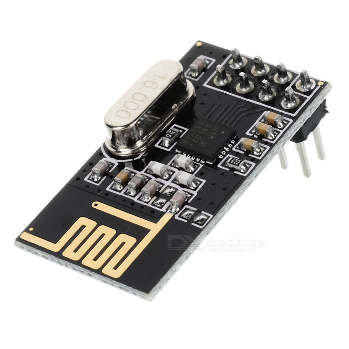
One of the best features of this module, aside from the ease with which it can be used with Arduino and other microcontrollers, is its low power consumption. This module consumes, less than 14mA in full communication mode and consumes only a few microamps in power down mode. This makes it ideal for projects with long battery life specifications.
To demonstrate the use of this module with Arduino, we will build a simple transmitter and receiver project. The transmitter sends data at a regular interval to the receiver which displays the received data on the serial monitor. This dummy data being transferred could be data from sensors in a real life application or signals to get the receiver to perform certain actions.
Required Components
The following components are required to build this project;
The exact components used for this tutorial, as usual, can be bought via the links attached to them.
Schematics
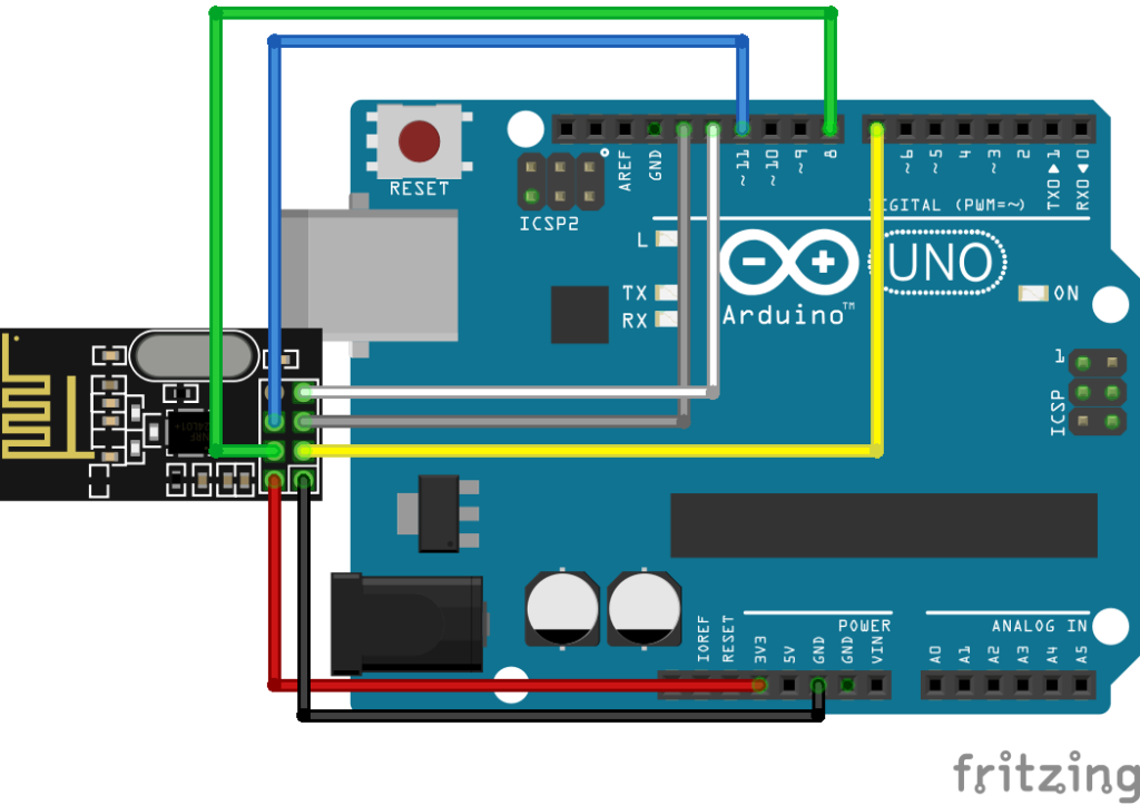
The schematics for this project is quite simple, all we need to do is to connect the NRF24L01 to the Arduino. The NRF24l01’s design is not breadboard friendly, so we will have to connect it to the Arduino with jumper wires.
Connect the components as shown in the schematics below.
Don’t forget that the same component will be used to build both the transmitter and receiver so we only need to replicate this for the receiver too.
To make the connection easier to follow and implement, a pin map showing which pins of the Arduino to which the RF module is connected, is shown below.
NRF24L01 – Arduino
GND - GND
VCC - 3.3v
CE - D7
CS - D8
SCK - D13
MOSI - D11
MISO - D12
It’s important that the NRF24L01 module’s VCC pin is not connected to the Arduino 5v pin as this will damage the NRF24L01 module. It is a 3.3V device.
Code
We will write two different Arduino sketches for this project. One of the sketches will be for the transmitter and the other one, for the receiver. The transmitter sketch basically performs the task of sending data at time intervals to the receiver which after receiving the message, prints it on the serial monitor. Both the transmitter and the receiver code are heavily reliant on the RF24 library which can be downloaded from here.
To do a brief explanation of the code starting with the Transmitter, the first thing we do, as usual, is to include the libraries that we will be using for the sketch which in this case is the SPI library which comes with the Arduino IDE and the RF24 library mentioned above.
#include <SPI.h>
#include "RF24.h"
Next, we create an instance of the RF24 library with the pins of the Arduino to which the CE and the CS pins of the NF24Lo1 are connected as arguments.
RF24 myRadio (7, 8);
Next, we create the struct package which is basically a function to package the data to be sent after which we move to the void setup function.
struct package
{
  int id=1;
  float temperature = 18.3;
  char  text[100] = "Text to be transmitted";
};


typedef struct package Package;
Package data;
Under the void setup function, we initialize the NRF24L01 module setting communication parameters like power level, channel, and data rate. It is important to pay attention to the channel used on the transmitter as the same channel needs to be used on the receiver.
void setup()
{
  Serial.begin(115200);
  delay(1000);
  myRadio.begin();
  myRadio.setChannel(115);
  myRadio.setPALevel(RF24_PA_MAX);
  myRadio.setDataRate( RF24_250KBPS ) ;
  myRadio.openWritingPipe( addresses[0]);
  delay(1000);
}
With the above done, we then write the void loop function.
The void loop function generates the dummy data to be sent to the receiver by increasing the value assigned to the dummy variable temperature in the struct package by 1 every time the loop runs. After generating the data, it is sent to the receiver using the myradio.write() function which is located at the beginning of the loop.
void loop()
{
  myRadio.write(&data, sizeof(data));

  Serial.print("\nPackage:");
  Serial.print(data.id);
  Serial.print("\n");
  Serial.println(data.temperature);
  Serial.println(data.text);
  data.id = data.id + 1;
  data.temperature = data.temperature+0.1;
  delay(1000);

}
The second sketch for the receiver is similar to the first, this sketch receives data from the transmitter and displays it on the serial monitor. We start this sketch also by including the libraries that are needed for it.
#include <SPI.h>
#include "RF24.h"
Next, we create an instance of the RF24 library also with the pins of the Arduino to which the CE and CS pins of the NRF24L01 is connected after which we create the struct package to which the temperature data is received.
RF24 myRadio (7, 8)
struct package
{
  int id=0;
  float temperature = 0.0;
  char  text[100] ="empty";
};

byte addresses[][6] = {"0"};
Next, is the void setup function. Just as we did for the transmitter’s sketch, we will initialize the RF module setting the communication parameters to match the parameters in the transmitter sketch.
void setup()
{
  Serial.begin(115200);
  delay(1000);

  myRadio.begin();
  myRadio.setChannel(115);
  myRadio.setPALevel(RF24_PA_MAX);
  myRadio.setDataRate( RF24_250KBPS ) ;
  myRadio.openReadingPipe(1, addresses[0]);
  myRadio.startListening();
}
With the above done, we write the void loop function. The void loop function for the receiver is fairly simple when data is available, we read the data using the myRadio.read function and display it on the serial monitor.
void loop()
{

  if ( myRadio.available())
  {
    while (myRadio.available())
    {
      myRadio.read( &data, sizeof(data) );
    }
    Serial.print("\nPackage:");
    Serial.print(data.id);
    Serial.print("\n");
    Serial.println(data.temperature);
    Serial.println(data.text);
  }

}
The complete sketch for both the transmitter and receiver is attached to the zip file under the download section
Demo
Upload the corresponding sketch to each board and keep the board on which the receiver code is running connected to the computer so you can view the data being displayed over the serial monitor. After a while, you should see the data from the transmitter being displayed on the serial monitor as shown in the Image below.
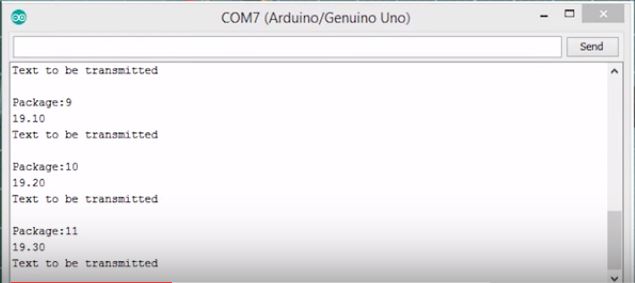
All though we used dummy data for this tutorial, this could have been a real-life data being sent from one Arduino to the other providing a solution to a real-life problem. That’s it for this tutorial guys, let me know via the comment section if you build any cool stuff based on this tutorial.
The video version of this tutorial can be watched on youtube here.
Till next time, cheers!
its Not Working at all. I am Using NRF24l01+ and it showing nothing and receiving nothing.
In the arduino platform they mentioned as uno cannot work as slave.please help me to solve my problem sir.
thanks in advance.
You should check if the problem is the adapter, some NRF24L0 need this.
It is not working with receiving module. I tried Uno and Nano, both of them failed. No idea why which put me in situation i can not use these modules for any aproject at all.
this Problem
test:25:28: error: ‘addresses’ was not declared in this scope
myRadio.openWritingPipe( addresses[0]);
I’m not sure if this is going to help, but this code looks incomplete.
copy and paste the following for the beginning of the code, continue the rest.
this will result in no errors so you can at least proceed.
#include
#include “RF24.h”
#include
#include
#include // include libraries
/* create instance of RF24 lib with the pins of the arduino
* CE and CS pins are connected as arguments */
RF24 myRadio (7,8);
byte addresses[][6] = {“0”}; // creates array of 6 bytes
// create struct package function to package data to be sent
// data will be sent in the void setup function from this
struct package {
int id=1;
float temperature = 18.3;
char text [100] = “This text is transmitted”;
};
typedef struct package Package;
Package data;
void setup()
{
Serial.begin(115200);
delay(1000);
myRadio.begin();
myRadio.setChannel(115);
myRadio.setPALevel(RF24_PA_MAX);
myRadio.setDataRate( RF24_250KBPS ) ;
myRadio.openWritingPipe( addresses[0]);
delay(1000);
}
void loop() {
myRadio.write(&data, sizeof(data));
Serial.print(“\nPackage:”);
Serial.print(data.id);
Serial.print(“\n”);
Serial.println(data.temperature);
Serial.println(data.text);
data.id = data.id + 1;
data.temperature = data.temperature+0.1;
delay(1000);
}