

Real Time Clock On 20×4 I2C LCD Display with Arduino
- Nick Koumaris
- http://educ8s.tv
- info@educ8s.tv
- 80.877 Views
- moderate
- Tested
- 0 Likes

Introduction
Sometimes it may be necessary to use a display while making a hardware project, but the size and the type of the display may vary according to the application. In a previous project, we used a 0.96″ I2C OLED display, and in this project we will have an I2C 20×4 character display.
Project Parts
This tutorial will describe how to use 20 x 4 LCD display with Arduino to print a real-time clock and date.

This liquid crystal display has 4 lines, 20 character in each line and cannot be used to display graphics. The main feature of this display that it uses I2C interface, which means that you will need only two wires to connect with Arduino. At the back side of the screen there is a small PCB soldered in the display, this circuit is a serial LCD 20 x 4 module and it also has a small trimpot to adjust the contrast of the LCD.
Display’s backlight is blue and the text is white. It is fully compatible with Arduino and has 5V input voltage. Its I2C address could be 0x27 or 0x3F. You can get it for about $7 from Bangood store.
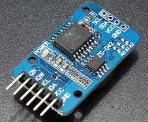
DS3231 is a low-cost, accurate I2C real-time clock (RTC), with an integrated temperature-compensated crystal oscillator (TCXO) and crystal. The device incorporates a battery input, so that if power is disconnected it maintains accurate time.
RTC maintains seconds, minutes, hours, day, date, month, and year information. Less than 31 days of the month, the end date will be automatically adjusted, including corrections for leap year. The clock operates in either the 24 hours or band / AM / PM indication of the 12-hour format. Provides two configurable alarm clock and a calendar can be set to a square wave output. Address and data are transferred serially through an I2C bidirectional bus.
This RTC module operates at input voltage range between 3.3V and 5.5V, so it can be connected with 3.3V or 5V pins. It is available on Banggood store for about $2.
Connecting the LCD with Arduino UNO
At first we will connect the LCD with Arduino to display some text and to learn how it works.
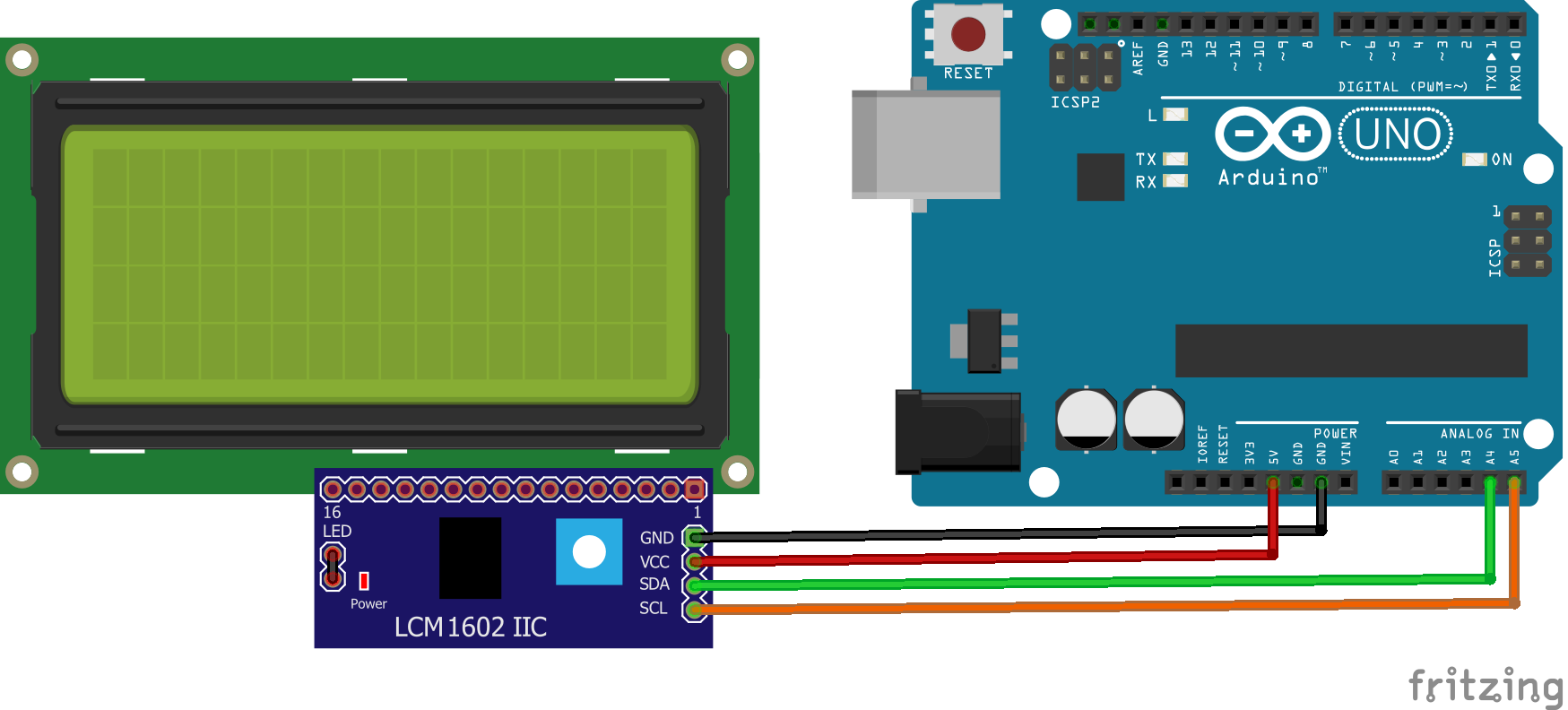
The Circuit
Connect the GND with Arduino GND, VCC with 5V pin on Arduino, SDA with A4 pin, and finally SCL with A5 pin.
The Code
First we need to download the library of the display, which includes all required functions to configure and write on the display. You can find it here.
Unzip the library and add it to the Arduino libraries folder, then run Arduino IDE and copy the following code. The first two lines are to include both of I2C and LCD libraries.
lcd.setCursor(3,0) will set the cursor of the LCD in the specified location, the first argument for the column and the second for the row starting form 0.
lcd.print(” “) will print the given text at the current cursor position, be careful that the overflowed characters will be discarded.
//Written by Nick Koumaris
//info@educ8s.tv
//educ8s.tv
#include <Wire.h>
#include <LiquidCrystal_I2C.h>
LiquidCrystal_I2C lcd(0x27, 2, 1, 0, 4, 5, 6, 7, 3, POSITIVE); // Set the LCD I2C address
void setup()
{
lcd.begin(20,4); // Initialize LCD
lcd.setCursor(3,0); // Set the cursor at the 4th column and 1st row
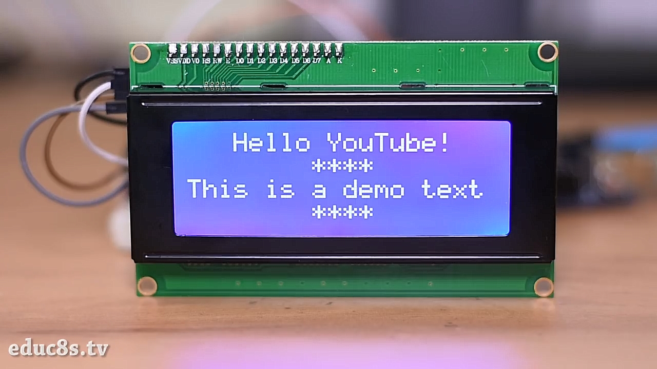
lcd.print("Hello YouTube!");
lcd.setCursor(8,1); // Set the cursor at the 9th column and 2nd row
lcd.print("****");
lcd.setCursor(0,2); // Set the cursor at the 1st column and 3rd row
lcd.print("This is a demo text");
lcd.setCursor(8,3); // Set the cursor at the 9th column and 4th row
lcd.print("****");
}
void loop()
{
}
Printing Date & Time on The LCD
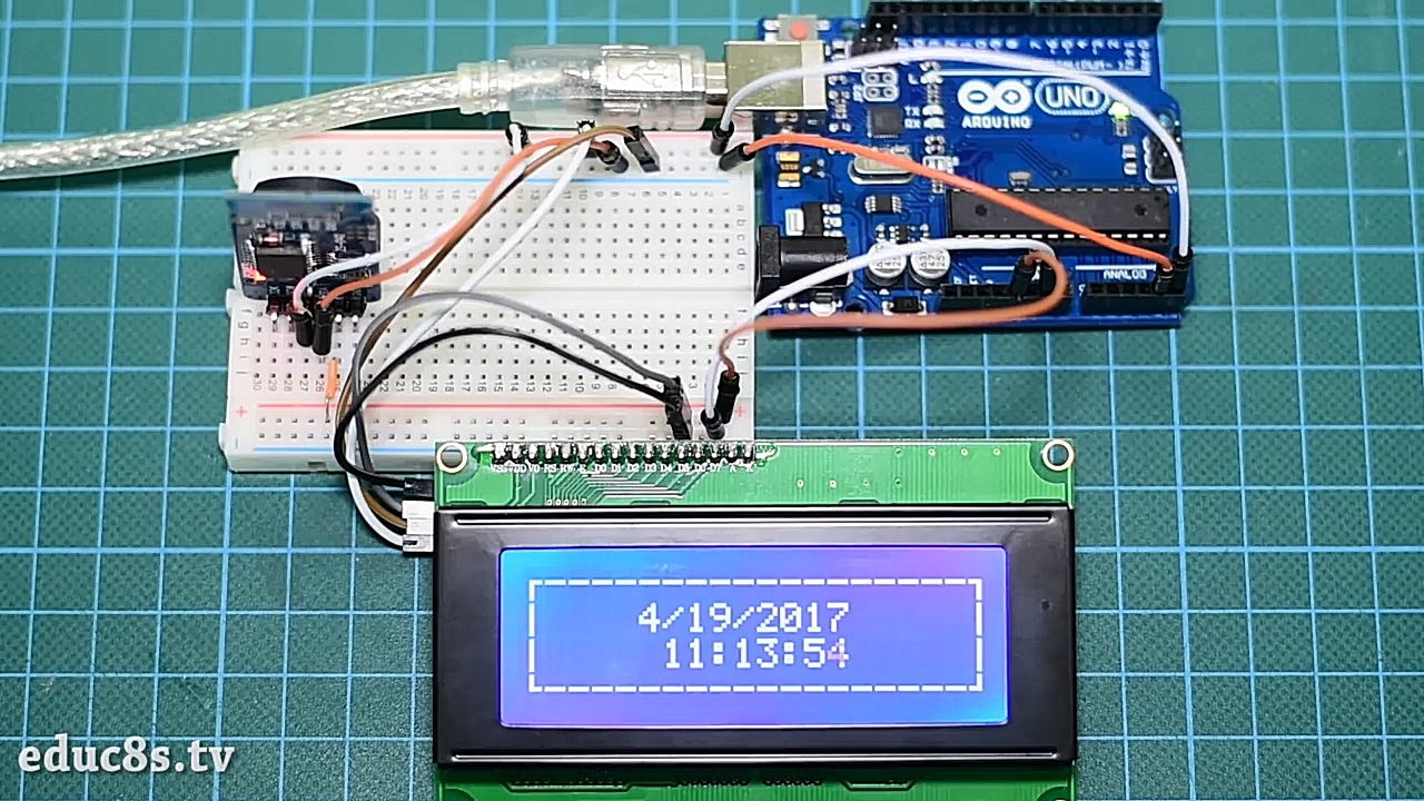
Now we will use the RTC module with the LCD to print current date and time, each of them in a line with a dashed border around them.
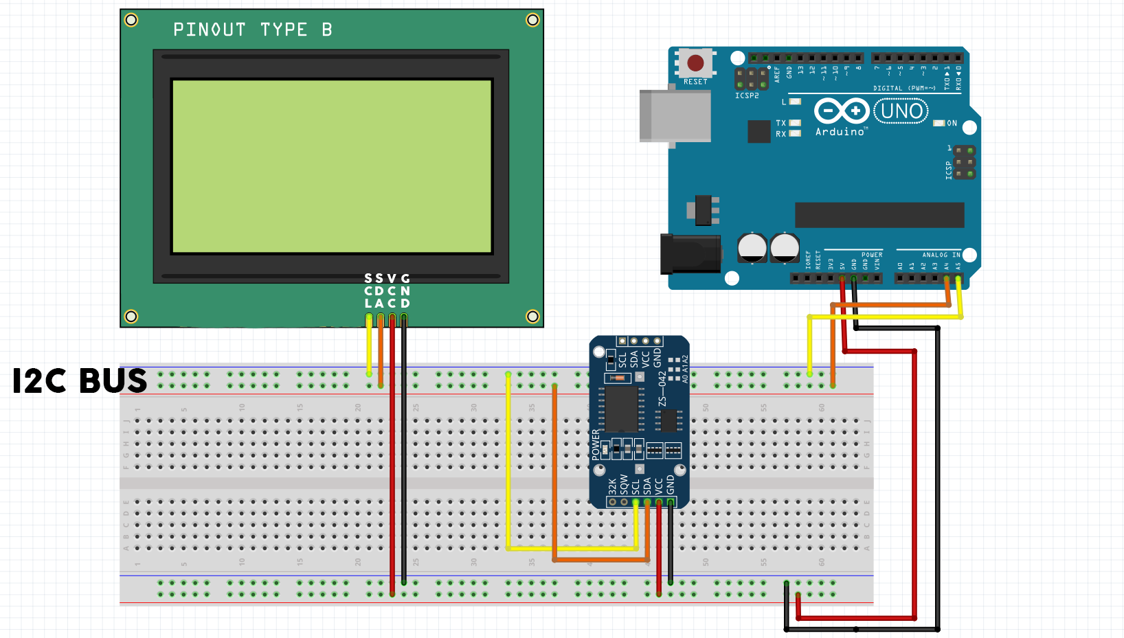
The Circuit
Here we will use a small breadboard to connect the RTC module and display with the Arduino’s I2C pins (A4 and A5). The SCL pins are connected with analog 5 pin and the SDA pins with analog 6 pin. The top rail of the breadboard used as I2C bus and the bottom one is power bus.
Connect both the display and the RTC module to 5 V and GND pins, and now the circuit is ready.
The Code
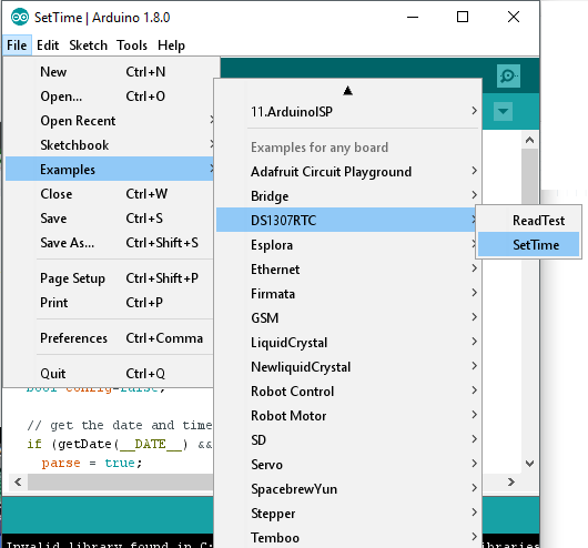 Before we start we have to download RTC library and set its time. The required library is available at github. Download it and extract it into Arduino libraries folder, then open Arduino IDE and from examples choose ‘setTime’ from DS1307 library. Finally upload it while the RTC module is connected with Arduino, and it will set its time as the computer time.
In addition to setup and loop function, we will create four other functions to organize the code. As the corners and vertical lines of the frame are special characters, we have to create them manually. So we will use a function to create them and another one to print them on the LCD.
Inside the loop function the time will be read from the real time clock module and the printed to the LCD using a custom function for each of time and date.
Now, let’s describe each part of code:
At first, we have to include the three libraries, I2C, LCD, and RTC and set the LCD address. Inside the setup function the display is initialized, then we will call createCustomCharacters() function and print them.
#include <Wire.h>
#include <LiquidCrystal_I2C.h>
#include <DS1307RTC.h>

LiquidCrystal_I2C lcd(0x27, 2, 1, 0, 4, 5, 6, 7, 3, POSITIVE);  // Set the LCD I2C address

void setup()
{
  lcd.begin(20,4);

  createCustomCharacters();

  printFrame();
}
Each character can be 5-pixel long in width and 8-pixel in height. So to create a custom character we need to create a new byte. We need 5 characters, the vertical line and the four corners. The yellow pattern shows you how the character will be displayed on the LCD.
Inside createCustomCharacters() function, we called lcd.createChar(#, byte array) function. The LCD supports up to 8 custom characters numbered from 0 to 7. It will assign the index in the first argument to the character given by the byte array. To print this character we can use lcd.write(byte(#)) function.
byte verticalLine[8] = {
  B00100,
  B00100,
  B00100,
  B00100,
  B00100,
  B00100,
  B00100,
  B00100
};

byte char2[8] = {
  B00000,
  B00000,
  B00000,
  B11100,
  B00100,
  B00100,
  B00100,
  B00100
};

byte char1[8] = {
  B00000,
  B00000,
  B00000,
  B00111,
  B00100,
  B00100,
  B00100,
  B00100
};

byte char3[8] = {
  B00100,
  B00100,
  B00100,
  B00111,
  B00000,
  B00000,
  B00000,
  B00000
};

byte char4[8] = {
  B00100,
  B00100,
  B00100,
  B11100,
  B00000,
  B00000,
  B00000,
  B00000
};

void createCustomCharacters()
{
  lcd.createChar(0, verticalLine);
  lcd.createChar(1, char1);
  lcd.createChar(2, char2);
  lcd.createChar(3, char3);
  lcd.createChar(4, char4);
}
Now after preparing our characters we can now print the frame.
This function is very simple, it uses lcd.setCursor(#,#) to move the cursor and lcd.print(“”) to print the given string. The function will print the top and bottom horizontal lines, then printing other custom characters.
void printFrame()
{
  lcd.setCursor(1,0);
  lcd.print("------------------");
  lcd.setCursor(1,3);
  lcd.print("------------------");
  lcd.setCursor(0,1);
  lcd.write(byte(0));
  lcd.setCursor(0,2);
  lcd.write(byte(0));
  lcd.setCursor(19,1);
  lcd.write(byte(0));
  lcd.setCursor(19,2);
  lcd.write(byte(0));
  lcd.setCursor(0,0);
  lcd.write(byte(1));
  lcd.setCursor(19,0);
  lcd.write(byte(2));
  lcd.setCursor(0,3);
  lcd.write(byte(3));
  lcd.setCursor(19,3);
  lcd.write(byte(4));
}
As we discussed earlier, the loop function will get the current time and date every second and refresh them on the display. First we defined a time element “tm” which has current time data, then if the time is correct and the RTC module working fine the time and date will be printed.
We can add some instructions so, if the DS1307 is stopped or there is a circuit error,we can light a LED to indicate the problem. The loop will wait for 1 second before starting the next iteration.
void loop()
{
   tmElements_t tm;

  if (RTC.read(tm)) {
    printDate(5,1,tm);
    printTime(6,2,tm);

  } else {
    if (RTC.chipPresent()) {
      //The DS1307 is stopped. Please run the SetTime
    } else {
      //DS1307 read error! Please check the circuitry
    }
    delay(9000);
  }
  delay(1000);
}
PrintTime function uses three arguments, the column and line where it will print the time, and the time element. lcd.print(tm.Hour) will print the hour, then if the minutes and seconds are less than 10 we will add 0 to the left. And the same method is used to print the date.
void printTime(int character,int line, tmElements_t tm)
{
  String seconds,minutes;
  lcd.setCursor(character,line);
  lcd.print(tm.Hour);
  lcd.print(":");
  if(tm.Minute<10)
  {
    minutes = "0"+String(tm.Minute);
    lcd.print(minutes);
  }else
  {
    lcd.print(tm.Minute);
  }
  lcd.print(":");
  if(tm.Second<10)
  {
    seconds = "0"+String(tm.Second);
    lcd.print(seconds);
  }else
  {
    lcd.print(tm.Second);
  }
}

void printDate(int character,int line, tmElements_t tm)
{
  lcd.setCursor(character,line);
  lcd.print(tm.Month);
  lcd.print("/");
  lcd.print(tm.Day);
  lcd.print("/");
  lcd.print(tmYearToCalendar(tm.Year));
}
Now everything is ready, upload the code to your Arduino and enjoy watching your new clock. You can find the full Arduino sketches and libraries in the attachment below.
This tutorial is made by educ8s.tv channel, and you can find the tutorial video below:


when i tried to connect RTC and LCD 20X4 through i2c ,am getting rtc values but display is not working on Arduino mega 2560 board…someone can u plz help me to solve the issue…. thanks in advance…
the sketch is given here in parts. You must copy and paste each function to an Arduino and complete one sketch with the parts given here. It works! I don`t know why, if someone is teaching us, the code is not complete in the firs time. This don`t help newbees to learn, as this discourages learners when the sketch don`t work for them. Hoerver, thanks to the author for this piece of treasure!
Hello,
in case anyone has an 16×2 LCD and wants 1s show
Here is the modified code:
#include
#include
#include
#include
LiquidCrystal_I2C lcd(0x27, 2, 1, 0, 4, 5, 6, 7, 3, POSITIVE); // Set the LCD I2C address
void setup()
{
Serial.begin(9600);
lcd.begin(16, 2);
lcd.backlight();
}
void loop()
{
delay(1000);
tmElements_t tm;
if (RTC.read(tm)) {
printDate(0,0,tm);
printTime(0,1,tm);
} else {
if (RTC.chipPresent()) {
//The DS1307 is stopped. Please run the SetTime
} else {
//DS1307 read error! Please check the circuitry
}
delay(9000);
}
}
void printTime(int character,int line, tmElements_t tm)
{
String seconds,minutes;
lcd.setCursor(character,line);
lcd.print(tm.Hour);
lcd.print(“:”);
if(tm.Minute<10)
{
minutes = "0"+String(tm.Minute);
lcd.print(minutes);
}else
{
lcd.print(tm.Minute);
}
lcd.print(":");
if(tm.Second<10)
{
seconds = "0"+String(tm.Second);
lcd.print(seconds);
}else
{
lcd.print(tm.Second);
}
}
void printDate(int character,int line, tmElements_t tm)
{
lcd.setCursor(character,line);
lcd.print(tm.Day);
lcd.print("/");
lcd.print(tm.Month);
lcd.print("/");
lcd.print(tmYearToCalendar(tm.Year));
}