What is a System ?
- Kamran Jalilinia
- kamran.jalilinia@gmail.com
- 15 min
- 236 Views
- 0 Comments
Introduction
The system is a general name that indicates several meanings and concepts. The Merriam-Webster dictionary defines a system as “a regularly interacting or interdependent group of items forming a unified whole”. A physical system is a unit or a combination made up of physical objects as its elements/ components and possibly subsystems, which act together and perform a certain objective; like a computer system or a power distribution system. A subsystem can also be considered a system itself.
A system, like a physical device or circuit, can be represented as a black box that shows how the system produces an output signal in response to an input. A signal is also a description of how one parameter varies with another parameter; For example, voltage changing over time in an electronic circuit. A block diagram of a system is a pictorial representation of the functions performed by each component and the flow of signals. It can be obviously useful to simplify the description of sophisticated systems containing several elements. Figure 1 shows a block diagram of a simple system with input and output ports.

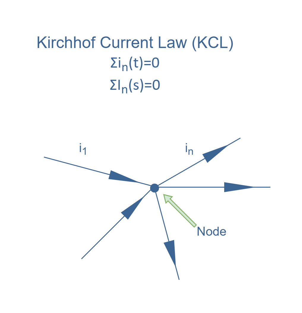
The behavior of systems is often governed by certain physical laws or constraints; for example, Kirchhoff’s laws of voltage and current in electrical systems (KVL & KCL). In terms of system theory, the problem is to find how the system transforms the input signal into the output signal. To design or analyze the performance of a given system, the first step is to establish a mathematical model based on physical laws, usually in the form of a set of (differential) equations. The output results are then extracted from input signal values by solutions of the mathematical model.
In system theory, for a linear, time-invariant (LTI) system, it is appropriate to use the transfer function (also known as system function or network function) of a system as a mathematical model (in the Laplace domain) that relates to the output response to the input variable.
The transfer function of an LTI system is defined as the ratio of the Laplace transform of the output (response function) to the Laplace transform of the input (driving function) under the assumption that all initial conditions are zero. The transfer function is the property of a system itself, independent of the magnitude and nature of the input or driving function. By applying Laplace transform we switch our analysis from a function of time to a function of the variable s (complex frequency):

Therefore, as a more complete representation of a system block diagram, the transfer functions (usually denoted by H(s) or T(s)) of the components are entered in the building blocks (Figure 2). This representation is so powerful because they simplify understanding of systems i.e. the transfer functions reduce the differential equations to simple algebraic equations.

In system theory, some rules are used for naming signals. First, continuous-time signals use parentheses, such as x(t) and y(t), while discrete-time signals use brackets, as in x[n] and y[n]. Second, time-domain signals use lower case letters. Upper case letters are reserved for the frequency or Laplace domain alternatively. Figure 3 shows how we can symbolize a system.

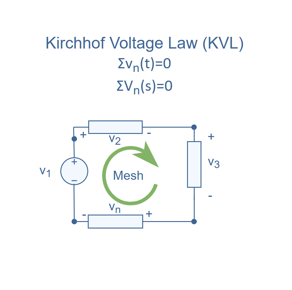
In electric circuit theory, a circuit can be composed of resistors, capacitors, inductors, voltage and/or current sources, etc. The analysis of this system is normally based on the circuit topology i.e. a schematic diagram of the circuit containing the symbols of its elements, their connections, and numerical values relating its terminal voltage and current for each of these circuit elements at every instant of time. when the voltage-current relation for each element is specified, Kirchhoff’s voltage and current laws can be applied possibly together with the physical principles (Figure 4). Then, the mathematical model can be created.
As a simple example for circuit theory analysis, Figure 5 describes a system consisting of an RC circuit using an input voltage source with the instant value of vi(t) and output of measured voltage of vc(t) across the capacitor:

In this electric RC circuit, application of KVL and Ohm’s Law leads to the following differential equation describing the input/output behavior:

Another method, as mentioned above, is to find the equation in the Laplace domain.
we can place the equalities as:
Z1 = R and Z2 = (1/Cs)
Then, we can use the voltage divider concept with the voltage across the capacitor as the output response. The transfer function is then obtained as:

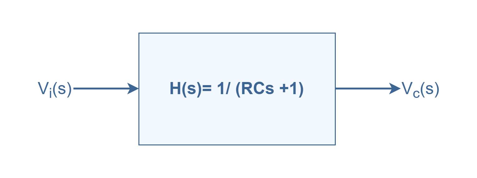
Again, we can characterize the RC circuit as a system with its transfer function and input/ output signals in such a way as shown in Figure 6:
The Feedback system
According to the concept of control theory, systems can generally be considered in two different categories: open-loop and closed-loop.
An ‘open-loop’ is a type of system in which the input is transformed into the output, but there is not any return path from the output port to the input port. It means that the input is independent of the process output. A good example is an electric heater controlled only by a timer, so that heat is applied for a constant period of time, regardless of the temperature of the environment. We can suppose that such a general open-loop system consists of 2 sub-systems that are placed in a cascaded configuration and the flow of procedure is unidirectional, as shown in Figure 7.

In this case, R(s) is the input signal in Laplace (complex frequency) domain and C(s) is the output response of system 1. But, because of cascading, the output of the first block plays the role of the input signal for the second block. Finally, the output signal of the whole system is B(s). So we have such equations:
C(s) = G(s)R(s), and B(s) = H(s)C(s); then we conclude: B(s) = H(s)G(s)R(s).
Therefore, the total transfer function for the above open-loop system is:
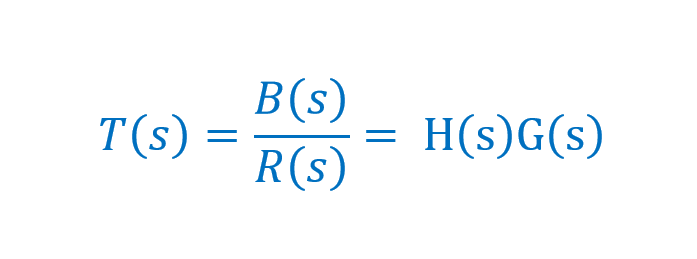
In this configuration, the output B(s) is just a linear response to the input variations of R(s).
Now, if the sub-systems are interconnected in a loop (or return path) from the output of one (system 1) to the input of the other (system 2), it is said to be a ‘closed-loop system’ as indicated by Figure 8. In this configuration, the feedback stage (system 2) receives information from the previous output data. In this mechanism a portion of the output is ‘fed back’ to the summing point in the input stage, where it is compared with input R(s) as the reference.
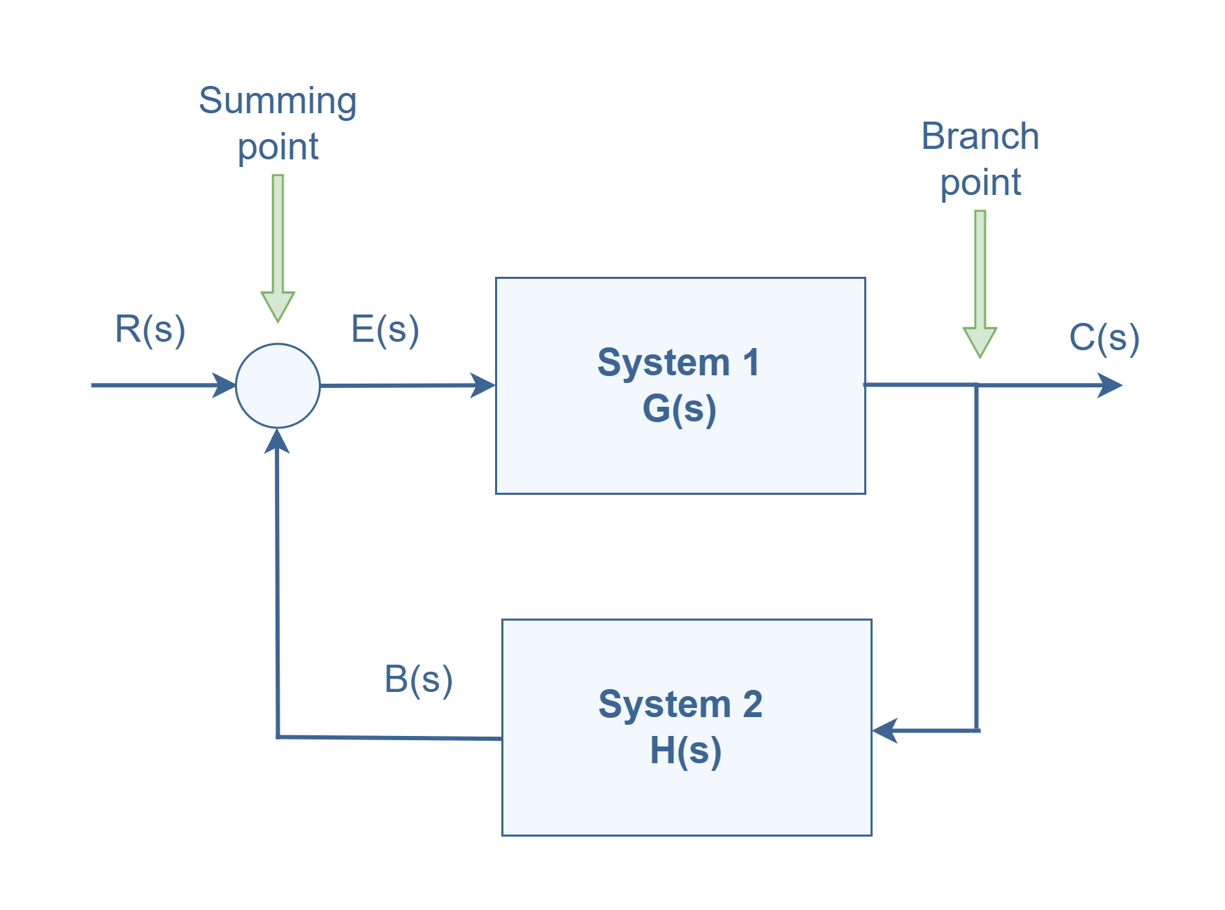
Any linear control system may be represented by a block diagram consisting of blocks, summing points, and branch points. The output of the system 1 block, C(s) in this case, is obtained by multiplying the transfer function G(s) by the input to the block, E(s) i.e. C(s) = G(s)E(s). This conversion is accomplished by the feedback element whose transfer function is H(s), as shown in Figure 8. In this arrangement, the feedback signal that is fed back to the summing point for comparison with the input is: B(s) = H(s)C(s). Therefore, by this establishment of a return path, the total output may be made a function of both the input and the previous outputs of the system.
In a closed-loop control system the difference between the input signal and the feedback signal (which may be the output signal itself or a function of the output signal), is called the error signal; which is denoted by E(s) in Figure 8. This signal is fed to the input for making a correction value accordingly in order to reduce the system error and bring the output of the system to the desired value. The ‘system’ can be almost anything; for example, an amplifier circuit.
In practice, the terms feedback control and closed-loop control are used interchangeably. The feedback concept is the method if appropriately applied, tends to make systems self-regulating. When the output is added to the input, the method is called positive feedback. Similarly, when the output is subtracted from the input, it is called negative feedback.
Naturally, in most practical systems there might be some imperfect internal calibrations that cause errors in performance. Moreover, in most systems, there are possibly external disturbances which are signals that tend to harmfully affect the values of the output. Additionally, the consequence of such negative effects may cause the output result to be different from what is already desired. The open-loop control configuration has the advantage of reducing in the complexity of the system design, but its main disadvantage is that it cannot correct any errors happening because of variations and disturbances.
On the other hand, an advantage of the closed-loop control system is the fact that the use of (negative) feedback makes the system response relatively insensitive to external disturbances and internal variations in system parameters i.e. preserving system stability. It is thus possible to use relatively inaccurate and low-cost components to obtain the accurate control of a given procedure, whereas doing so is impossible in the open-loop case.
Positive Feedback
The positive feedback adds the reference input, R(s), and feedback output. Figure 9 shows the block diagram of the positive feedback control system.
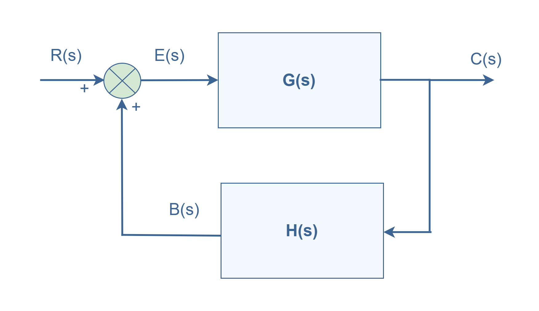
Because E(s) = R(s) + B(s), we can find the overall transfer function of the system:

Negative Feedback
Negative feedback reduces the error between the reference input, R(s), and system output by subtracting these signals. Figure 10 shows the block diagram of the negative feedback control system.
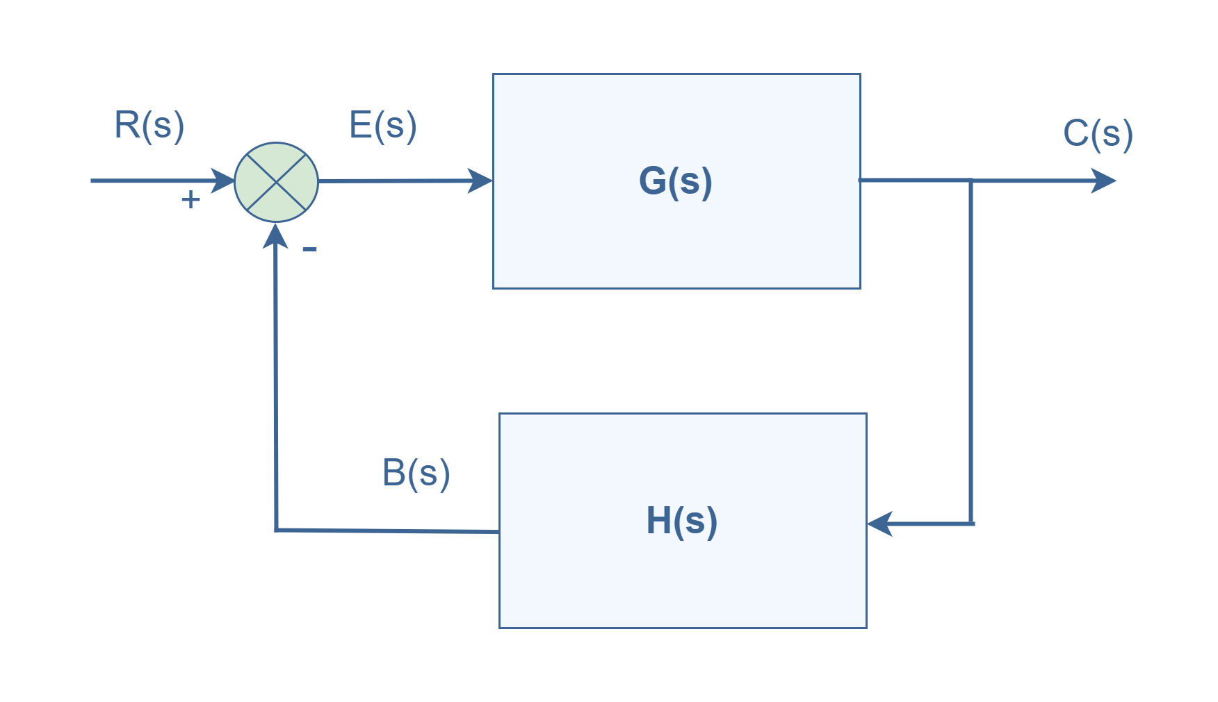
Because E(s) = R(s) – B(s), we can find the overall transfer function of the system by this error signal:

Conclusion
After reviewing the basic principles of the feedback concept, we can summarize the following points.
- Open-loop systems are normally less applicable because they do not have low-cost reliable methods to control their performance.
- Closed-loop systems are widely used because of their advantages. While between the two types of feedback systems, the positive feedback method is rarely used. By considering its transfer function in Equation 5, we can find out that the denominator of [1-G(s)H(s)] is a critical term. If the product of G(s)H(s) approaches to one, the T(s) value will be raised high up to a dangerous result and the system will become unstable; like the problem of oscillation and runaway conditions.
- From Equation 6, it is clear that the overall gain of the negative feedback system is the ratio of G(s) and (G(s)H(s)). So, the overall gain might be decreased depending on the value of [G(s)/ (1+ G(s)H(s))] rather than single forward gain G(s) and this is a disadvantage.
- If the value of G(s)H(s) is chosen enough greater rather than 1, thus: [1+ G(s)H(s)] ≈ G(s)H(s), and then T(s) ≈ 1/ H(s). It means the overall transfer function of the system will be independent of forwarding gain G(s) and the performance of such systems just depend on the feedback loop gain H(s). By using stable components in this part, it is possible to make a stable performance for all the systems; as a great advantage.
- In general, G(s) and H(s) are functions of frequency. So, the overall gain of the feedback system can be changed in different ranges of frequency.
- Based on design features of negative feedback, Noise and Distortion can be eliminated in the system because of the nature of its transfer function.
More tutorials in Systems
- The Fourier Analysis –The Fast Fourier Transform (FFT) Method
- The Fourier Analysis – Discrete Fourier Transform (DFT)
- Analog To Digital Conversion – Performance Criteria
- Analog To Digital Conversion – Practical Considerations
- Analog To Digital Conversion – Decoding Signals
- Analog To Digital Conversion – Binary Encoding
- Analog To Digital Conversion – Sampling and Quantization
- The Fourier Analysis – Fourier Transform
- The Fourier Analysis – Fourier Series Method
- Introduction to Signals and Systems Analysis


