FT93xRTC External Power Switch Circuit
This application note describes implementing a simple circuit for the FT930/FT931RTC external power supply switch. The Texas Instruments SN74AUC2G53 Single-Pole Double-Throw (SPDT) analog switch is used to select the power supplied by the 1.5V battery or by the 1.2V internal LDO.
This application note describes implementing a simple circuit for the FT930/FT931RTC external power supply switch. The Texas Instruments SN74AUC2G53 Single-Pole Double-Throw (SPDT) analog switch is used to select the power supplied by the 1.5V battery or by the 1.2V internal LDO. You can find other interesting Electronic circuits in this Circuits library
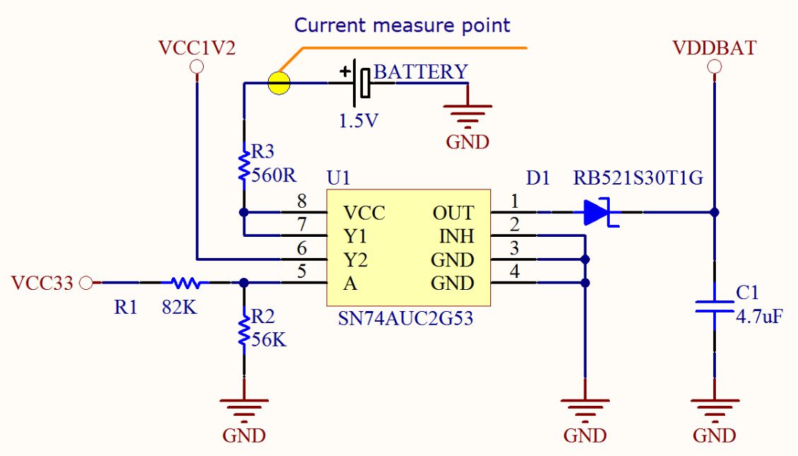
This circuit has two power source inputs (VCC1V2 and 1.5V Battery) and one output (VDDBAT). VCC33is used as a control signal via the resistor divider circuit R1 and R2.VCC1V2 is the internal regulator out put of the FT930/FT931;it connects to VCC33 internally.U1is a Texas Instruments SN74AUC2G53 Single-PoleDouble-Throw (SPDT) analog switch. It can operate from 0.8V to 2.7V with low power consumption. It can still operate if the battery voltage drops to 0.9V.
FT93xRTC External Power Switch Circuit – [PDF]


