Arduino Real Time Clock with DS1302 and Nokia 5110 LCD Display
Introduction Hi guys, in one of our previous tutorials, we made a real time clock, using the DS3231 RTC Module and the 1602 LCD display module. For this tutorial, we will be building something similar using the DS1302 RTC module and the Nokia 5110 display module.
Introduction
Hi guys, in one of our previous tutorials, we made a real time clock, using the DS3231 RTC Module and the 1602 LCD display module. For this tutorial, we will be building something similar using the DS1302 RTC module and the Nokia 5110 display module. Unlike the 1602 LCD module which was used in the previous tutorial, the Nokia 5110 LCD module has the ability to display customized graphics which will help us display our data with better UX.
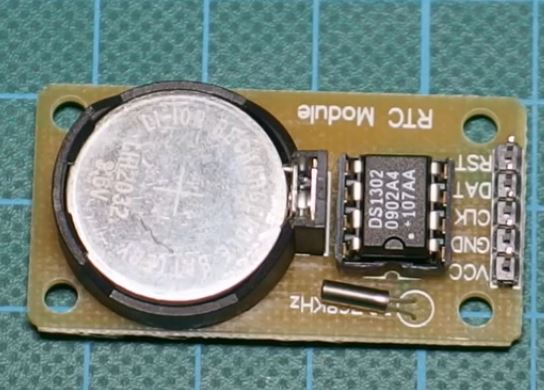
At the core of this project is the DS1302 RTC module which is a trickle-charge timekeeping chip which contains a real-time clock/calendar and 31 bytes of static RAM. The real-time clock/calendar provides seconds, minutes, hours, day, date, month, and year information to the micro controller or processor to which its connected via a simple serial interface. The end of the month date is automatically adjusted for months with fewer than 31 days, including corrections for leap year. The device could be set to operate in either the 24-hour or 12-hour format with an AM/PM indicator.
Interfacing the DS1302 with a micro controller like the arduino is simplified by using synchronous serial communication. Only three wires are required to communicate with the clock/RAM: reset, data line, and CLK (serial clock). Data can be transferred to and from the clock/RAM 1 byte at a time or in a burst of up to 31 bytes. The DS1302 is designed to operate on very low power and retain data and clock information on less than 1µW.
The module is a successor to the DS1202 RTC module and asides the basic timekeeping functions of the DS1202, the DS1302 has the additional features of dual power pins for primary and backup power supplies, programmable trickle charger for VCC1. This capability makes it ideal for a long term real time clock project.
Required Components
The following components will be needed to build this project;
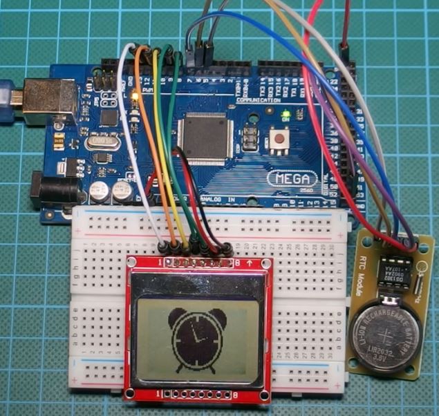
Schematics
Connect all components as shown in the fritzing schematics below.
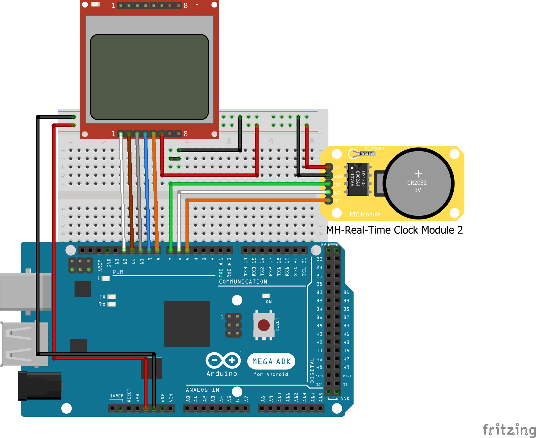
The DS1302 module has a 3-wire communication interface with which it interacts with the microcontroller. A breakdown of its connection to the Arduino is given below, to make the schematics clearer.
DS1302 - Arduino
VCC - 5v
GND - GND
Clk - D7
DAT - D6
RST - D5
A detailed tutorial has been made before on how to use the nokia 5110 LCD module with the arduino and can be found here. It will help you better understand how the nokia 5110 connection with the arduino works. For this project however, the pin connection of the Nokia 5110 LCD to the Arduino (as shown in the schematics) is given below;
LCD - ARDUINO
Pin 1(RST) – D12

Pin 2(CE) – D11

Pin 3(DC) – D10

Pin 4(DIN) – D9

Pin 5(CLK) – D8

Pin 6(VCC) - VCC

Pin 7(LIGHT) - GND

Pin 8(GND) - GND
All done?, lets write the code.
Code
To make writing the code easy for us, the first thing we need to do is to download the msparks ds1302 library from github. After downloading the library, extract it and paste into your arduino libraries folder after which we can launch our arduino IDE to start writing the code.
P.S: for those who have not been following the series of tutorials, its important to note that, to use the Nokia 5110 LCD with the Arduino easily, we need to download the Nokia 5110 LCD library that was made by rinky-dink electronics. The library does most of the heavy lifting and makes it easy for us to write codes to control the LCD. Click here to visit the download page and then download the LCD5110_graph zip file. You can check out this tutorial to know more about using the Nokia 5110 LCD display.
The zip file attached at the bottom of the page contains two files; the code file and the graphics file, which is an hex file for a clock icon. For this project, we will be displaying a clock icon on the LCD asides from the data from the RTC, just to give things a better look. Detailed explanation on how to display your own custom graphics on the Nokia 5110 LCD display was done during on of our previous tutorial here.
As usual, we will do a break down of the code explaining each part, so you can better understand the process.
The first thing we need to do like with every other code, is include all the libraries we will be using.
//Written by Nick Koumaris
// info@educ8s.tv
//educ8s.tv
#include <LCD5110_Graph.h>
#include <stdio.h>
#include <DS1302.h>
Next, we declare the pins to which our LCD is connected and declare the font size along with other parameters for the LCD.
LCD5110 lcd(8,9,10,12,11);
extern unsigned char BigNumbers[];
extern unsigned char SmallFont[];
extern uint8_t clock[];
Next, we create a namespace for the RTC. we first declare the pins on the Arduino to which the RTC is connected, and then proceed to create a ds1302 object with the clock, data and reset pin as inputs. Next was setting the cases that returned a particular kind of day.
namespace {

const int kCePin   = 5;  //RST
const int kIoPin   = 6;  //DAT
const int kSclkPin = 7;  //CLK

// Create a DS1302 object.
DS1302 rtc(kCePin, kIoPin, kSclkPin);

String dayAsString(const Time::Day day) {
  switch (day) {
    case Time::kSunday: return "Sunday";
    case Time::kMonday: return "Monday";
    case Time::kTuesday: return "Tuesday";
    case Time::kWednesday: return "Wednesday";
    case Time::kThursday: return "Thursday";
    case Time::kFriday: return "Friday";
    case Time::kSaturday: return "Saturday";
  }
  return "(unknown day)";
}
}
With this done, we then proceed to the setup function. The first thing we do is set the time on our RTC. this command needs to only run once in the lifetime of our project. we will never need to set the time again even when the device goes off for a while because the DS1302 has a battery back up with which it can run for years without losing track of time/date. after the first run, the line of code is commented out and the code uploaded to the microcontroller again.
void setup() {

 setTime();
After setting the time, we then initialize the LCD and clear the screen to get it ready to display new data.
lcd.InitLCD();
 lcd.clrScr();
Next, we display the clock icon, which can be imported into your code by clicking on sketch on the IDE and selecting add file. Navigate to where the file is and add to your code. After drawing the Icon and issueing the update command to the LCD to display it, we then insert a delay of some seconds to give the icon enough to time to show on the screen.
lcd.drawBitmap(0, 0, clock, 84, 48);
lcd.update();
delay(3000);
with the setup all done. we are ready to move to the loop function.
The loop function contains just two lines of code as emphasis was on making the code as modular as possible. the first line of code is the printtime() function which handles printing the current date and time on the LCD. the second is a delay function which ensure the data being displayed stays on the screen long enough to be seen.
void loop() {

 printTime();
 delay(1000);
}
Next we move to the printtime() function which actually handles the display of time from the rtc on the LCD. the first line gets the time and calendar information from the rtc and stores in the variable “t” which is of type “time”. After this is done, we then declare the names of the variables that will hold both time and calendar information, from month to date.
void printTime() {

  Time t = rtc.time();

  const String day = dayAsString(t.day);
  String month;
  String date;
  String hour;
  String minutes;

  month = String(t.mon);
  date = String(t.date);
  hour = String(t.hr);
  minutes = String(t.min);

 String fullDate = day+" "+month+"/"+date;
Next, the screen is cleared, font selected and the time and date are displayed.
lcd.clrScr();
  lcd.setFont(SmallFont);
  lcd.print(fullDate,0,0);

  lcd.setFont(BigNumbers);

  if(t.hr<10)
  {
    hour = "0"+hour;
    lcd.print(hour,7,18);
  }else
  {
        lcd.print(hour,7,18);
  }
  lcd.print(".",35,18);
  if(t.min<10)
  {
    minutes = "0"+minutes;
    lcd.print(minutes,47,18);
  }else
  {
      lcd.print(minutes,47,18);
  }
  lcd.update();
}
The last function (Void Settime()) is for setting the time as the ds1302 module does not come with the clock, correct.
To set the time, the first thing we need to do is turn off write protection for the ds1302 rtc module, so we can address it’s registers. Next, we start the operation of the rtc using the rtc.halt(false) command. With this done the device is ready to receive data, so we input the current time and date with kthursday if its a Thursday or kmonday, if it’s a Monday.
void setTime()
{
  rtc.writeProtect(false);
  rtc.halt(false);
  Time t(2015, 2, 26, 13, 35, 50, Time::kThursday); //Change this line to set time  ex 2015 26/2 9:09:50
  rtc.time(t);
}
Go over the code and be sure everything is at it should be, then upload to your Arduino board.
The Full code for the project is available below and attached in the zip file at the end of this post along with the hex file for the clock Icon.
//Written by Nick Koumaris
// info@educ8s.tv
//educ8s.tv
#include <LCD5110_Graph.h>
#include <stdio.h>
#include <DS1302.h>

LCD5110 lcd(8,9,10,12,11);
extern unsigned char BigNumbers[];
extern unsigned char SmallFont[];
extern uint8_t clock[];

namespace {

const int kCePin   = 5;  //RST
const int kIoPin   = 6;  //DAT
const int kSclkPin = 7;  //CLK

// Create a DS1302 object.
DS1302 rtc(kCePin, kIoPin, kSclkPin);

String dayAsString(const Time::Day day) {
  switch (day) {
    case Time::kSunday: return "Sunday";
    case Time::kMonday: return "Monday";
    case Time::kTuesday: return "Tuesday";
    case Time::kWednesday: return "Wednesday";
    case Time::kThursday: return "Thursday";
    case Time::kFriday: return "Friday";
    case Time::kSaturday: return "Saturday";
  }
  return "(unknown day)";
}
}

void setup() {

 setTime();
 lcd.InitLCD();
 lcd.clrScr();
 lcd.drawBitmap(0, 0, clock, 84, 48);
 lcd.update();
 delay(3000);
}

void loop() {

 printTime();
 delay(1000);
}

void printTime() {

  Time t = rtc.time();

  const String day = dayAsString(t.day);
  String month;
  String date;
  String hour;
  String minutes;

  month = String(t.mon);
  date = String(t.date);
  hour = String(t.hr);
  minutes = String(t.min);

 String fullDate = day+" "+month+"/"+date;

  lcd.clrScr();
  lcd.setFont(SmallFont);
  lcd.print(fullDate,0,0);

  lcd.setFont(BigNumbers);

  if(t.hr<10)
  {
    hour = "0"+hour;
    lcd.print(hour,7,18);
  }else
  {
        lcd.print(hour,7,18);
  }
  lcd.print(".",35,18);
  if(t.min<10)
  {
    minutes = "0"+minutes;
    lcd.print(minutes,47,18);
  }else
  {
      lcd.print(minutes,47,18);
  }
  lcd.update();
}

void setTime()
{
  rtc.writeProtect(false);
  rtc.halt(false);
  Time t(2015, 2, 26, 13, 35, 50, Time::kThursday); //Change this line to set time  ex 2015 26/2 9:09:50
  rtc.time(t);
}
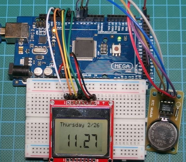
Demo
Copy the code, paste in the Arduino IDE, and upload to your arduino board, you should get an output like the image below on your screen. Don’t forget to include the icon file in the Arduino sketch folder.
That’s it for this tutorial guys. As usual, let me know if you have any questions via the comments section.
The youtube video of this tutorial is available here.
hello.. its time to say bye bye to the arduino programming.. tough for beginners.. download flowcode, a powerfull graphical software which makes easy to program any component with arduino.
Grayelectronics.tech
download here fully patched version free