Build your own 0-24V/3A Lab Power Supply with current limit
I have always believed that one of the best things about being a maker, is the ability to build your own tools, and we have covered the development of several tools like this in the past. For today's tutorial, we will add another tool to the list, as I will be sharing a guide on how you can build a robust, fully-functional, Lab Bench Power Supply.
I have always believed that one of the best things about being a maker, is the ability to build your own tools, and we have covered the development of several tools like this in the past. For today’s tutorial, we will add another tool to the list, as I will be sharing a guide on how you can build a robust, fully-functional, Lab Bench Power Supply.
As with most tools, there are several DIY guides on the internet, but for today’s tutorial, I will be share how to build the “Super Lab Power Supply” built by “Danielrp“. Just like his LiPo battery tester which we covered a while back, the Super Lab Power supply comes in a beautiful enclosure that takes into account the importance of functionality without compromising aesthetics.
Highlight features of the superb lab power supply include:
- Nominal Voltage: 24V.
- Nominal Current: 3A.
- Output Voltage Ripple: 0.01% (According to the specs of the power supply circuit kit).
- Voltage measurement resolution: 10mV.
- Current measurement resolution: 1mA.
- CV and CC modes.
- Over-current protection.
- Overvoltage protection.
The SuperLab Power Supply is based on the super cheap VkMaker adjustable DC regulated power supply DIY module being sold on eBay. The power supply, which comes as a kit with THT type components and a PCB (so its easy to solder), takes in 24V AC supply at its input and gives between 0-30V at its output depending on user input via an onboard potentiometer. The module is able to supply up to 3A current and is equipped with safety features that help prevent overload and shorts.
While the module had all that is needed to regulate and vary the voltage/current, it lacks feedback features that could make it more useful. For example, unless you connect a voltmeter/ammeter to the output terminals, there is no feedback to know what effects turning the potentiometer has on the output. To provide this desired feedback and other features in a digital and neat way, Daniel developed a metering circuit based on an Arduino Uno. The metering circuit, which is designed as an Arduino Shield, sits in-between the output of the VKmaker PSU and the load, measuring the voltage and current at the output of the Vkmaker PSU and displaying it in an innovative way on a 20×4 LCD.
Asides monitoring the voltage and current, the metering circuit also includes pushbuttons that are used to turn the device “ON” or “OFF”, along with a few additional potentiometers which can be used in setting the point at which the device initiates overvoltage and overcurrent protection among others. All of these features helps ensure you can safely power devices for tests in the lab without worrying about possible damage to the circuit due to overvoltage or overcurrent.
The guide will be in a step by step manner and at the end of it, you should be able to build your own Lab Power Supply, potentially with upgrades.
Required Components
The following components are required to build this project;
- Arduino Uno
- 4×20 I2C LCD Display “2004”
- VK Maker Power Supply Kit
- Push Buttons (2)
- Pushbutton switch, main switch
- multiturn, linear, 10K potentiometers (2)
- 270º, 10k linear potentiometers (2)
- Potentiometer knobs
- Transformer 115/20 – 5A or 220/20 (depending on AC Supply ratings in your country)
- Black, red and green binding posts
- IEC Panel Male Plug with fuse holder
- IEC power cord
- Heatsink
- insulator sheet
- Aluminum enclosure
- Tall adhesive NYLON spacers
- Terminal lug
- Dry transfer letters
- 3/16″ Faston
- Assorted screws/nuts
- Metering Circuit/Shield
So the list does not become too long and messy, the BOM containing the components used for the metering shield is attached under the download section. It contains reference information needed to search for the components, most of which are available on Digikey.
With all the components in place, we can now proceed to put them together to build the project.
Assembling the power supply Kit
The assembly process for the power supply kit is fairly straight forward. The components in the kit are through-hole type, so all you will need to do is find where each component is meant to be on the board, place it, and solder it. Before soldering, it is important to ensure the orientation of the component is correct, especially for components like diodes and ICs, as placing them wrongly could damage the component itself or the whole board. To make the component placing easy, a table showing the labels on the PCB and the value of the component to be placed is provided below.
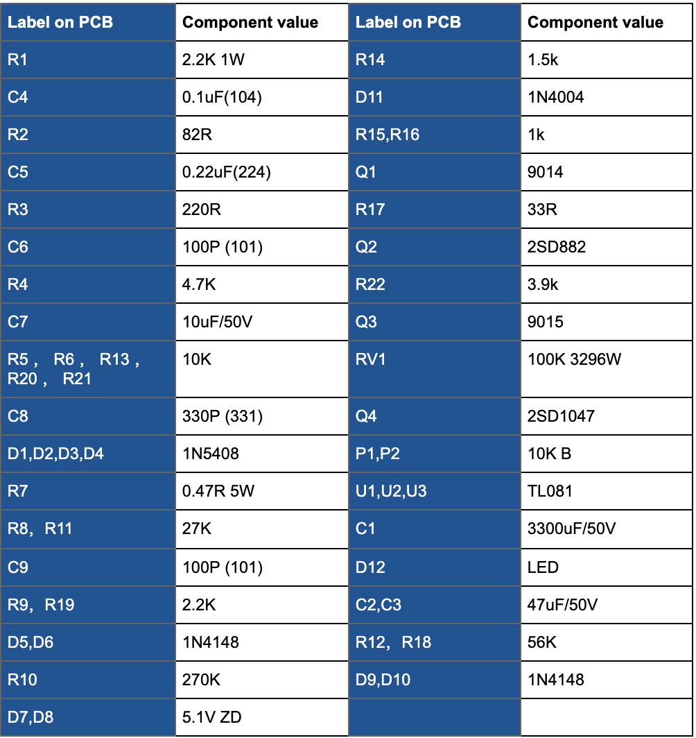
If you are not familiar with things like color coding for resistors, it might be helpful to have a meter with you to check the value of the resistors and confirm orientations before soldering. For ICs, you can look up the pinout diagrams/datasheets.
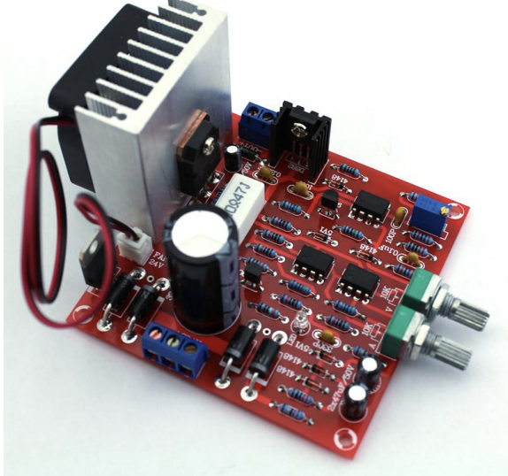
With all the components mounted, the board should look like the image below;
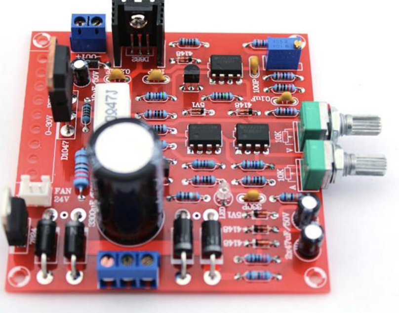
For the voltage and current adjustment potentiometers, you can solder them directly on the PCB as shown above, but to allow more flexibility for your enclosure, you should connect them to the board through socket and jumper wires as shown below.
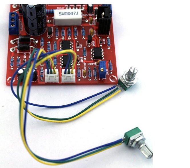
The potentiometer tagged with A is the current limit potentiometer and V is the voltage potentiometer. In place of the regular potentiometers, for easier and more accurate adjustments, you may replace the voltage potentiometer that came with the kit, with a 10K multi-turn wire-wound potentiometer.
With all the components soldered on the PCB, one last thing we need to do to test the power supply module is to install a cooling fin of considerable size, insulated from the circuit, on Q4 (D1047). A lot of heat will be generated at this end of the circuit and it could lead to a breakdown if it is not properly handled. If the cooling fin is not big enough, you can make use of a cooling fan. The 24V socket on the board was placed there for this purpose. After installing the cooling fin and fan, the board should look like the image below.
Go over the connections once again though to ensure everything is as it should be. With this done, the Power Supply is ready to go. We can now move to the other parts of the project.
Build the Metering Shield
Up next is the metering shield. As mentioned during the introduction, the metering shield helps digitize the controls and provides visual feedback to the user. It also implements the shutdown overvoltage and overcurrent features which disconnects the load via a relay.
As the name implies, the metering circuit was designed as a shield, compatible with all boards that have the layout and dimensions of the R3 version of the Arduino Uno. Due to the shielding nature, it was implemented on a PCB which was designed using Eagle CAD.
The schematics below show how the components are connected:
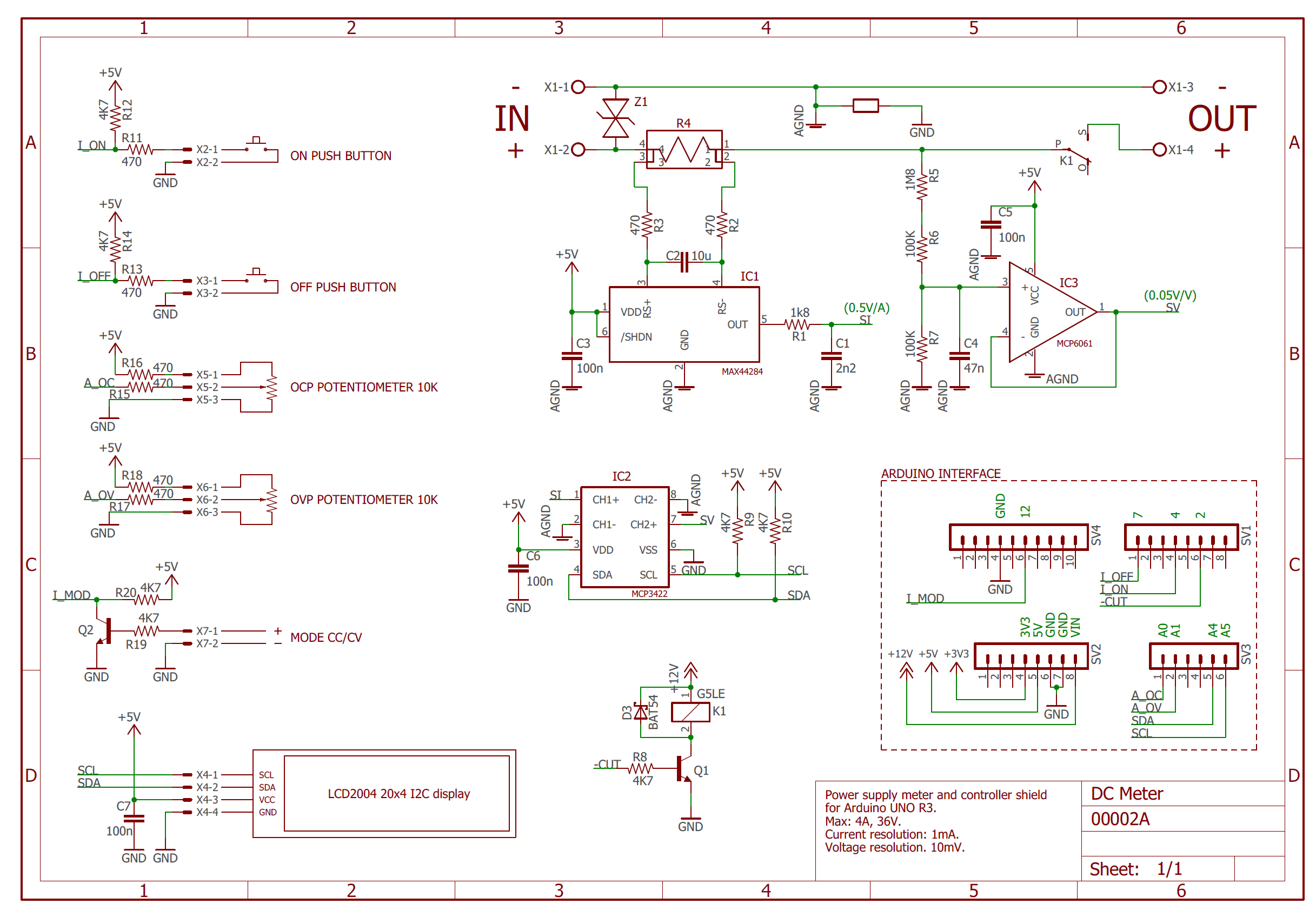
All design files including, schematics, PCB, and Gerber files are attached under the download section at the bottom of the page. This makes it easy for those who may like to make changes to the design and those who want to just ship the Gerbers off to fabricators and replicate the exact design.
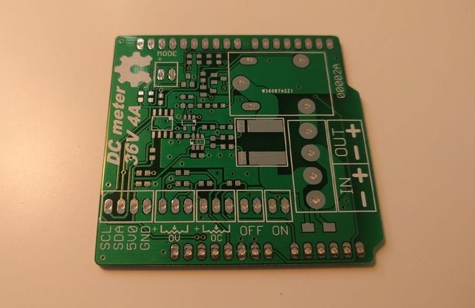
An image of the PCB after production is provided below.
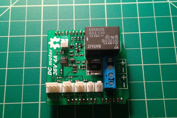
After assembly, the shield should look like the image below;
With the metering shield and the Power Supply all in place, its time to couple them together to create the Lab Power Supply.
Schematics
Connect the power supply, the metering shield, the Arduino, the display, and other parts of the system together as shown in the schematics below.
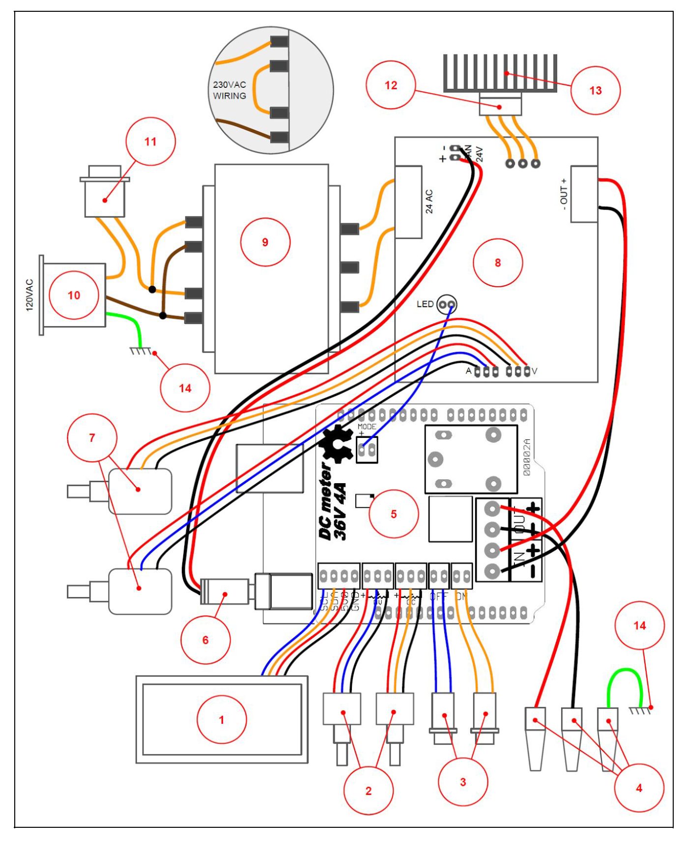
The schematics is labeled to make it easy to identify which component goes where. A lookup table for the labels on the schematic is attached under the download section.
AC power source to the system is feed via the transformer which steps the voltage down to 24Vac. It is important to note that the input AC Voltage to the Power Supply Module is 24v and ensure you use a transformer which is rated for such. The system might behave in an unstable manner if a voltage is higher than this. The output of the Vkmaker power supply circuit kit is connected to the IN terminal block of the metering shield and the OUT terminal block of the metering shield goes directly to the binding posts of the Lab power supply. The Arduino is powered over its DC power jack, with supply from the 24V terminal on the power supply.
With all the components connected, we can now proceed to examine the code for the project.
Code
The code for this project was developed using the Arduino IDE. Asides creating a fascinating user interface, the code basically displays the set voltage and current level of the power supply and updates the display as those values are changed by adjusting the potentiometers.
The code is quite bulky but I will try to go over the basic parts, and explain the role of each section.
The code started as usual, with the inclusion of the libraries that will be used. In this case, the I2C version of the liquid crystal library, along with the wire library was used. The wire library implements some of the functions required for I2C communication while the I2C Liquid Crystal library helps with displaying data on the I2C based LCD display. The wire library comes pre-installed with the Arduino IDE and the I2C Liquid Crystal library can be installed via the library manager or manually, via the attached link.
#include <Wire.h>
#include <LiquidCrystal_I2C.h>  //Library: https://bitbucket.org/fmalpartida/new-liquidcrystal/downloads/
Next, we specify the LCD type, along with the number of rows and columns.
//Conditional build:
#define LCD4x20
//#define LCD2x16

//LCD display parameters
#ifdef LCD4x20
  #define N_ROWS 4u
  #define N_COLS 20u
#endif //LCD4x20
#ifdef LCD2x16
  #define N_ROWS 2u
  #define N_COLS 16u
#endif //LCD4x20
#define LCD_TBL 5000u     //Time that backlight remain active
Next, we create some macros and variables that represent the state of the buttons and specific commands.
//Macros
//Relay
#define RELAY_ON    digitalWrite(2, HIGH); \
                    pinMode(2, OUTPUT)
#define RELAY_OFF   digitalWrite(2, LOW); \
                    pinMode(2, OUTPUT)
#define IS_RELAY_ON (HIGH == digitalRead(2))

//Aruduino builtin LED
#define STATUS_ON   digitalWrite(LED_BUILTIN, HIGH); \
                    pinMode(LED_BUILTIN, OUTPUT)
#define STATUS_OFF  digitalWrite(LED_BUILTIN, LOW); \
                    pinMode(LED_BUILTIN, OUTPUT)
//MODE Pin
#define INIT_MODE   pinMode(12, INPUT)                      //Config MODE pin
#define IS_MODE_CV  (HIGH == digitalRead(12))               //true if mode CV
//ON pushbutton
#define INIT_PON    pinMode(4, INPUT)                       //Config ON pushbutton pin
#define IS_PON_ON   (LOW == digitalRead(4))                 //true if ON pushed
//OFF pushbutton
#define INIT_POFF   pinMode(7, INPUT)                       //Config OFF pushbutton pin
#define IS_POFF_ON  (LOW == digitalRead(7))                 //true if OFF pushed
//OC potentiometer
#define READ_ADC_CP() analogRead(0)
//OV potentiometer
#define READ_ADC_VP() analogRead(1)
Next, we create variables related to the MCP3422 ADC, to hold the channel address and other values.
//MCP3422
#define MCP3422_CH1 0x00
#define MCP3422_CH2 0x01
//#define MCP3422_SR 0x00 //240 SPS (12bit)
#define MCP3422_SR 0x01 //60 SPS (14bit)
//#define MCP3422_SR 0x02 //15 SPS (16bit)
//#define MCP3422_SR 0x03 //3.75 SPS (18bit)
#define MCP3422_GAIN 0x00 //x1
//#define MCP3422_GAIN 0x01 //x2
//#define MCP3422_GAIN 0x02 //x4
//#define MCP3422_GAIN 0x03 //x8
#define MCP3422_CR_STARTONESHOT 0x80 // /RDY bit = 1, /O/C bit = 0
#define MCP3422_CR_READY 0x80        // /RDY bit mask
#define MCP3422_NCH 2u    //Number of channels available
#define MCP3422_ADD 0x68  //Slave address
#define MCP3422_TP 5u     //Number of msec between pollings to MCP3422
Next, we create some constants, especially those used in displaying special characters, like the progress bar, on the LCD.
//Special chars for progress bar
const uint8_t a6x8u8ProgressBarChars[6][8] =
{
  {0x00, 0x00, 0x00, 0x00, 0x00, 0x15, 0x00, 0x00},
  {0x00, 0x00, 0x10, 0x10, 0x10, 0x15, 0x00, 0x00},
  {0x00, 0x00, 0x08, 0x08, 0x08, 0x1D, 0x00, 0x00},
  {0x00, 0x00, 0x04, 0x04, 0x04, 0x15, 0x00, 0x00},
  {0x00, 0x00, 0x02, 0x02, 0x02, 0x17, 0x00, 0x00},
  {0x00, 0x00, 0x01, 0x01, 0x01, 0x15, 0x00, 0x00}
};
//Status messages
const char strStatusCC_ON[6]  = {"CC ON"};
const char strStatusCV_ON[6]  = {"CV ON"};
const char strStatusOFF[4]    = {"OFF"};
const char strStatusOV_OFF[7] = {"OV OFF"};
const char strStatusOC_OFF[7] = {"OC OFF"};
/////////////////////////////////////////////////////////////////////////////////////
//Display
//Double buffer..
#ifdef LCD4x20
char displayBufferA[N_ROWS][N_COLS] =
{
  {'V', 'O', '=', '0', '0', '.', '0', '0', 'V', ' ', ' ', 'C', 'O', '=', '0', '.', '0', '0', '0', 'A'},
  {'0', '0', '0', '0', '0', '0', '0', '0', '0', ' ', ' ', '0', '0', '0', '0', '0', '0', '0', '0', '0'},
  {'O', 'V', 'P', '=', '0', '.', '0', '0', 'V', ' ', ' ', 'O', 'C', 'P', '=', '0', '.', '0', '0', 'A'},
  {'S', 'T', 'A', 'T', 'U', 'S', ':', ' ', ' ', ' ', ' ', ' ', ' ', ' ', ' ', ' ', ' ', 'O', 'F', 'F'}
};
char displayBufferB[N_ROWS][N_COLS]=
{
  {'#', '#', '#', '#', '#', '#', '#', '#', '#', '#', '#', '#', '#', '#', '#', '#', '#', '#', '#', '#'},
  {'#', '#', '#', '#', '#', '#', '#', '#', '#', '#', '#', '#', '#', '#', '#', '#', '#', '#', '#', '#'},
  {'#', '#', '#', '#', '#', '#', '#', '#', '#', '#', '#', '#', '#', '#', '#', '#', '#', '#', '#', '#'},
  {'#', '#', '#', '#', '#', '#', '#', '#', '#', '#', '#', '#', '#', '#', '#', '#', '#', '#', '#', '#'}
};
#endif //LCD4x20
#ifdef LCD2x16
char displayBufferA[N_ROWS][N_COLS] =
{// 0    1    2    3    4    5    6    7    8    9    10   11   12   13   14   15
  {'V', '=', '0', '0', '.', '0', '0', ' ', '0', '0', '0', '0', '0', '0', '0', '0'},
  {'C', '=', '0', '.', '0', '0', '0', ' ', '0', '0', '0', '0', '0', '0', '0', '0'}
};
char displayBufferB[N_ROWS][N_COLS]=
{
  {'#', '#', '#', '#', '#', '#', '#', '#', '#', '#', '#', '#', '#', '#', '#', '#'},
  {'#', '#', '#', '#', '#', '#', '#', '#', '#', '#', '#', '#', '#', '#', '#', '#'}
};
#endif //LCD4x20
Next, we create some general parameters and variables like the max current and voltage, and output values among others that will be used in the code.
//General parameters
#define MAXVP 2600u           //Maximum OV in 1/100V units
#define MAXCP 3100u           //Maximum OC in 1/1000A units
#define DEBOUNCEHARDNESS 10u

//General variables
uint16_t u16VOValue = 0; //Voltage output value
uint16_t u16COValue = 0; //Current output value
uint16_t u16VPValue = 0; //Voltage protect value
uint16_t u16CPValue = 0; //Current protect value
uint16_t a3u16VP[3u] = {0, 0, 0}; //Array for filtering voltage protect
uint16_t a3u16CP[3u] = {0, 0, 0}; //Array for filtering current protect
uint8_t u8Index_a3u16VP = 0; //Index of a3u16VP
uint8_t u8Index_a3u16CP = 0; //Index of a3u16CP
bool bOnPressed = false;      //State of On push button
bool bLastOnPressed = false;  //Last state of On push button, used for flange detection
bool bOffPressed = false;     //State of Off push button
bool bLastOffPressed = false; //Last state of Off push button, used for flange detection
uint8_t u8OnDebounce = 0;     //Debounce counter for On push button
uint8_t u8OffDebounce = 0;    //Debounce counter for Off push button
bool bMODECV = false;         //Mode of power supply, true: constant voltage, false: constant current
uint32_t u32MCP3422Value = 0;       //Last conversion value from MCP3422
bool bMCP3422ValIsPositive = true;  //Last conversion sign, in this circuit it's always positive
bool bValuesOK = false;             //Indicates in the main loop if the last execution of MCP3422_Machine updated u16VOValue and u16COValue
/////////////////////////////////////////////////////////////////////////////////////
Next, we move to the void setup() function. We start the function by calling the setupDisplay() function which initializes the LCD with the right column and row numbers among other things. We follow this by setting the speed for wire communication so as to set the communication speed for the display and ADC, turn on the LCD backlight, and finally initialize the MCP ADC.
void setup()
{
  RELAY_OFF;
  setupDisplay();
  Wire.setClock(400000);  //Speed for both display and MCP3422
  restartBackLight();
  MCP3422_MachineInit();
}
Next, we write the void loop() function. The void loop function is quite simple thanks to all the functions doing the heavy lifting. The loop() starts with the UpdateInputs() function, which essentially fetches the state of the pushbuttons along with voltage and current value from the ADC.
void loop()
{
  updateInputs();
Next, we call the refreshbacklight() function which is called periodically to ensure the screen’s backlight is on. After this, we verify the state of the ADC and if all is ok, we call the updateStatus() function (which sets the state of the relay), followed by the updateDisplaybuffer() function which modifies the display buffer with current values of the measurements, Finally, we call the updateDisplay() function which browses through the displayBufferA. If any character is different in displayBufferA than displayBufferB writes it to displayBufferB and the LCD.
void loop()
{
  updateInputs();
  refreshBackLight();
  bValuesOK  = MCP3422_Machine();
  if(true == bValuesOK)
  {
    updateStatus();
    updateDisplayBuffer();
    updateDisplay();
  }
}
Other parts of the code are the functions that were called in the setup() and loop() functions and they are properly commented so they should be easy to understand.
The complete code for the project is bulky and might make the post unnecessarily long. To prevent this, the complete code for the project has been attached under the download section.
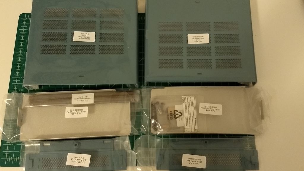
Enclosure
Consistent with Danielrp’s projects, the enclosure for this project is a beauty to behold. It is based on an aluminum enclosure from Cheval (their standalone SA-Series enclosure).
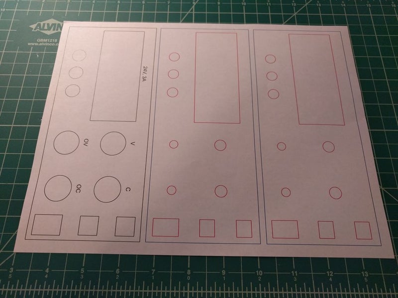
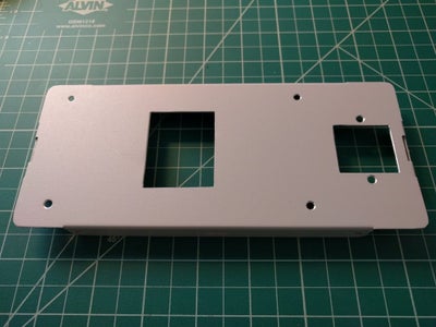
In the absence of a router to modify the enclosure to suit the needs of the power supply, the old way of cutting, trimming with file, and using transfer letters for the text, was adopted. An Inkscape file with the stencil used in cutting the front panel is attached to the zip file under the download section. You can print this and use it to trace out your design on the front panel or cut using a router.
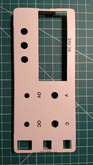
The front panel after cutting and trimming should look like the image below.
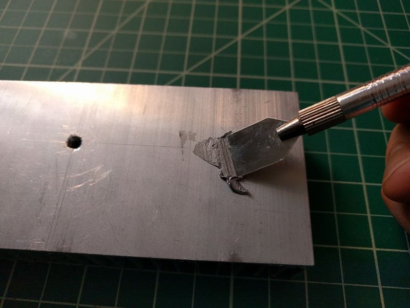
The back panel of the enclosure also requires modification so the heat sink and the IEC Connector for Power could be mounted. To achieve this, follow the steps below;
1. Mark the position of the heatsink, including the hole for the power transistor and the position of the holding screws.
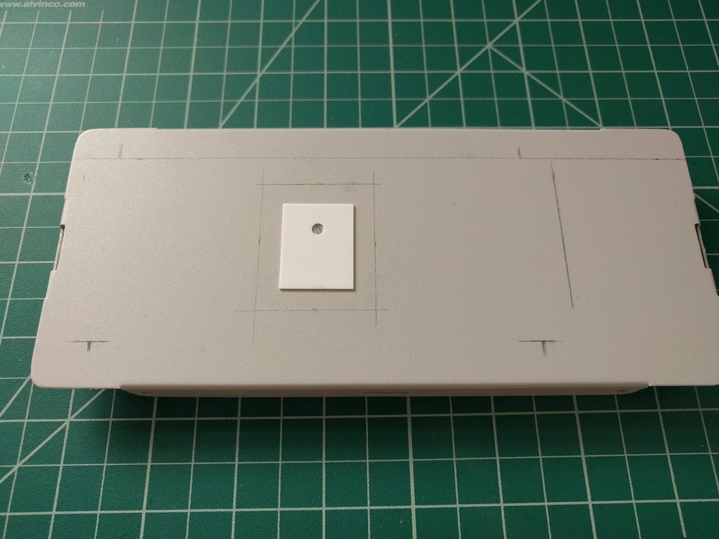
2. Mark the hole for accessing the heatsink from the interior of the power supply enclosure, I have used the insulator as a reference.
3. Mark the hole for the IEC connector.
4. Drill the contour of the shapes.
5. Drill the holes for the screws.
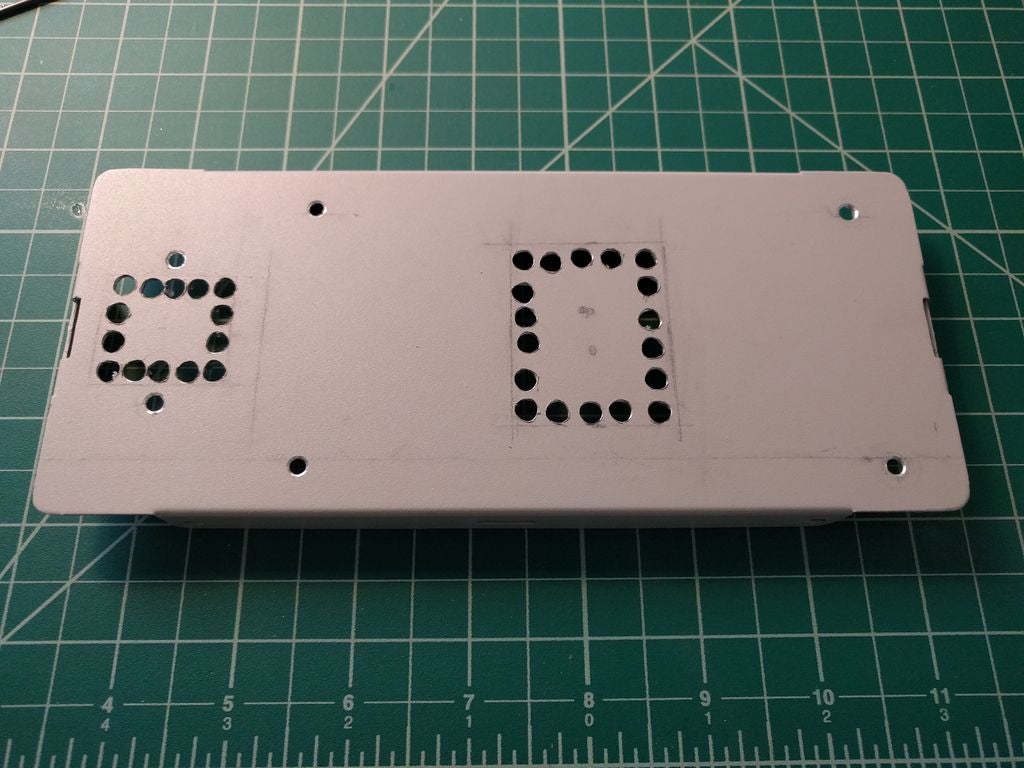
6. Cut the shapes with cutting pliers.
7. Trim the shapes with a file.
It is important to reiterate the importance of the heatsink at this point, as the power supply circuit is not self-protected against overheat. According to the datasheet the 2SD1047 transistor has a junction to case thermal resistance of Rth-j,c = 1.25ºC/W, as such, before buying a heat sink you must take into consideration its thermal resistance and evaluate its suitability based on other factors. A guide to understanding how heat sink calculations work is provided here. but for the sake of this project, this heat sink, with a thermal resistance of Rth-hs, air = 0.61ºC/W, was used and it seemed to be good enough after calculations.
Project Assembly
With the enclosure and electronics in place, it is time to assemble the electronics into the enclosure.
To start with the front panel, follow these steps to position the components;
- Strip out a multiconductor cable from scrap to get cables.
- Build the “Molex connector”, wire and shrinkable tube assembly for potentiometers, pushbuttons, and LCD. Remove any protuberance in potentiometers.
- Remove the pointer ring of knobs.
- Cut the rod of potentiometers to the size of the knob. I have used a piece of cardboard as a gauge.
- Attach the pushbuttons and power button.
- Assemble the potentiometers and install the knobs, the multiturn potentiometers have a ¼ inch shaft and the one turn models have a 6mm shaft. You can use washers as spacers to trim the distance of potentiometers.
- Screw the binding posts.
- Put a double-sided tape in the LCD and stick it to the panel.
- Solder the positive and negative wires to the binding posts.
- Assemble the GND terminal lug in the green binding post.
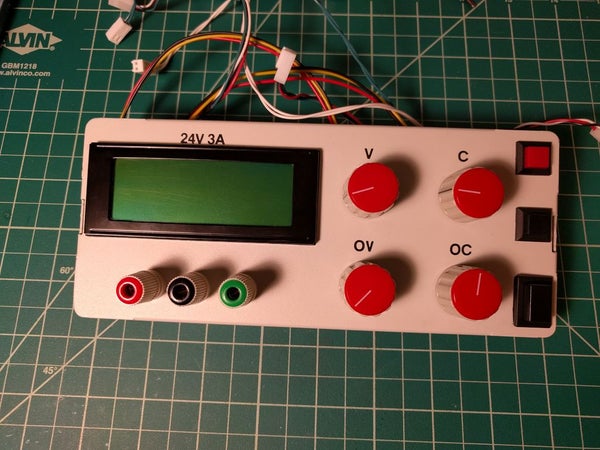
Front Panel After Assembly
With the front panel in place, arrange the back panel with the heat sink following the steps below;
1. While the paint on the enclosure is a good thermal isolator, you can add some heatsink grease to increase the heat transfer from the heatsink to the enclosure.
2. Screw the heatsink to the back panel.
3. Assemble the IEC connector.
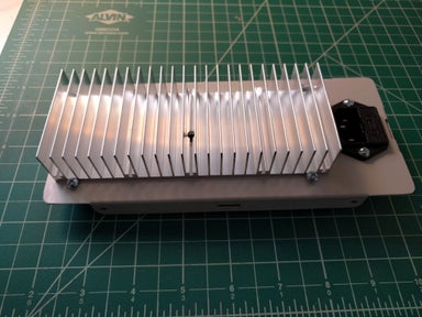
4. Position the adhesive spacers using the power supply kit circuit.
5. Screw the power transistor and the insulator, there must be thermal grease in each surface.
6. Assemble the 7812 for powering the Arduino, it should face the case to allow heat dissipation, using one of the screws that hold the heatsink. A plastic washer like this http://www.ebay.com/itm/100PCS-TO-220-Transistor-… could also be used but the project used the same insulator as the power transistor and a bent piece of the case.
7. Finally, Wire the power transistor and the 7812 to the power supply circuit.
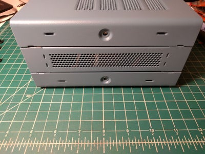
![]()
Finally, assemble the transformer, DC meter, Arduino + metering shield, and other components, in the enclosure. You can follow these steps to get that done;
- Mark and drill the holes for the transformer.
- Assemble the transformer.
- Stick the adhesive legs of the enclosure.
- Stick the DC meter circuit using adhesive spacers.
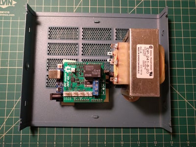
- Scrape the paint to screw the GND lug.
- Build the mains voltage wire assemblies, all the terminations are 3/16” Faston. Shrinkable tubes were used to isolate the terminations.
- Cut the front part of the holder of the enclosure on the right side to get space for the power pushbutton.
- Connect all wires according to the assembly guide provided under the schematics section.
- Install the Fuse (1A).
- Put the output voltage potentiometer (the VO potentiometer), to the minimum CCW and adjust the output voltage the closest possible to zero volts using the multiturn fine adjusting potentiometer of the vkmaker power supply circuit.
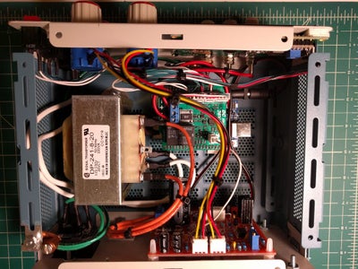
- Close up the enclosure.
with this done, the Super Lab Power Supply is now ready for testing and usage.
Demo
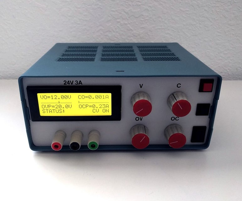
With all the components assembled and code uploaded to the Arduino, take a minute to admire yourself for a job well done, and plug in the power supply to your AC socket. Push the button and you should see the screen come up as shown in the image below. You should also see the progress bar(along with the voltage/current at the output) change as you turn the knob of the potentiometers.
Go ahead and test the other features and modify them until you are satisfied.
That’s it! Your very own lab power supply!!
Going Forward
So much advancement can be brought into this project thanks to the metering shield. One of the first things that come to mind is being able to control and monitor the power supply via an app over WiFi or Bluetooth by adding an ESP8266 WiFi or a BT/BLE module to the project. Do you have other cool ideas? share via the comment section.
References:
Looks like a great projecy,thanks fpr all the hard work.However – I can’t find the PCB gerber files!
Check above, I’ve uploaded the files.