


![[Sponsored Post] Infrared Wireless Relay Switch](https://www.electronics-lab.com/wp-content/uploads/2018/12/BE-01-0640-800x800-e1545127301104.jpg "[Sponsored Post] Infrared Wireless Relay Switch")
Do you find it hard to get up from your cozy bed at night, just to turn off the lights? Do you want to operate your home appliances simply by a click of your TV remote? Home appliances include all types of electrical equipment available in your home. It does not matter whether it is a washing machine or a coffee maker. So, if you are lazy enough or maybe just love using technology, this project is for you!
We will walk you through the build process of the infrared-based wireless switch. In simple terms, it is a switch that you can operate using your TV, DVD player or any other remote. The best part of this project is that PCBGOGO, a PCB manufacturing company based in China, makes it super easy to construct it. You no longer need to go through the hard and time-consuming process of making a PCB yourself. PCBGOGO has your back! And they don’t even charge much!
Circuit Diagram
Figure 1 shows the circuit diagram of this project. The wireless switch can be simply made by using TSOP1738 infrared receiver, decade counter CD4017 and other easy to find components.
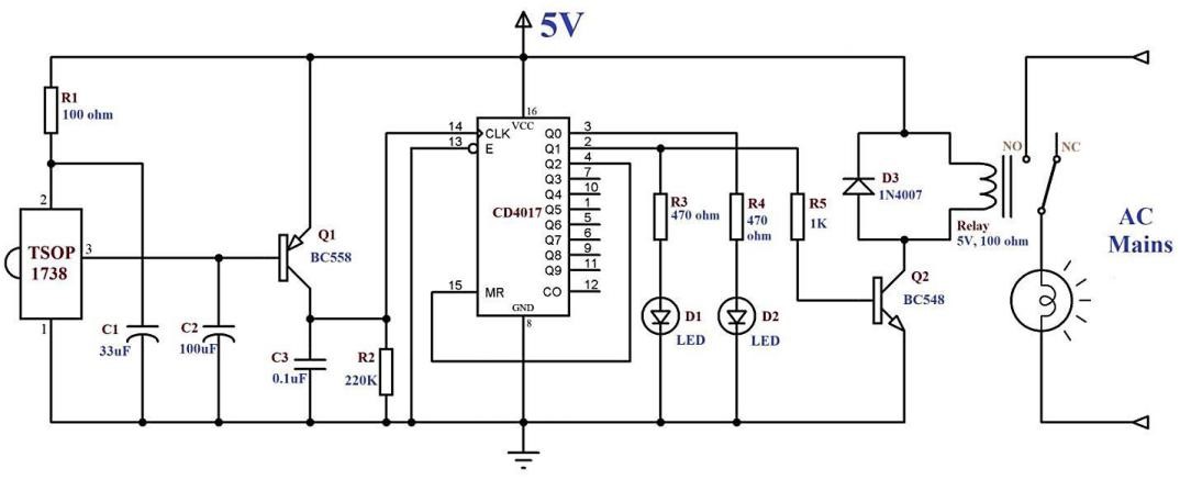
So, based on Figure 1, we will need the following components to begin making this wireless switch:
- Decade Counter CD4017
- Infrared Receiver TSOP1738
- 1N4007 Diode
- 7805 IC
- BC558 and BC548 transistors
- 100, 220k, 470 and 1k ohm resistors
- Two LEDS
- 33μF, 100μF and 0.1μF Capacitors
- Relay 5V, 100 Ω
Operation
Home remote controls such as your TV’s remote, emits infrared rays when any button is pressed. Each button produces its unique pattern of infrared waves. So, when you will press a button on your TV remote, IR rays will fall on TSOP1738 infrared receiver. Its output pin 3 will go low as it is active low and the transistor Q1 will amplify the signal to feed it to the clock input of CD4017.
Assuming that the decade counter is at reset state, output Q0 will go high and other outputs will be low. LED D2 will be glowing at this time, indicating that the appliance is in the off state. Clock signal will be generated in the decade counter as soon as it gets signal from the transistor Q1. Output Q1 will go high and LED D1 will start to glow. Transistor Q2 will also turn on and the relay will be energized. LED D1 will stop glowing at this time.
Now, to turn off the appliance, you will need to press the remote again. Q0 will again become high and LED D2 will start to glow, indicating that your appliance has been turned off. CD4017 is working as a bistable multivibrator as we have connected the output Q2 (4th pin) with Reset MR (15th pin). 16th and 8th pins are VCC and GND pins, respectively. 13th pin is the enable pin. It is connected to the ground since IC is active low.
Some other noteworthy connections are the 2nd and 1st pins of TSOP1738, they are the VCC and GND pins respectively. The 100 Ω resistor and 33μF capacitor are used to smooth the noise in power supply.
Placing an Order on PCBGOGO website
First of all, I designed my circuit schematic on Altium Designer software. After that, I made a PCB layout from the schematic and generated Gerber files. If you are not familiar with Altium, then this is not a problem, you can use any software that you are comfortable working with. All you need to do is to make a PCB layout of your circuit and generate Gerber files.
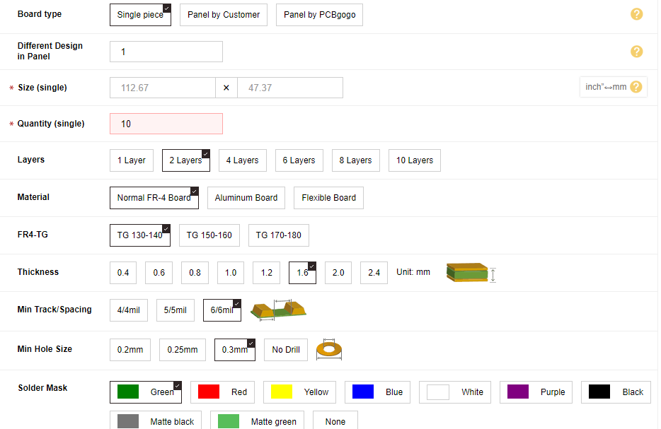
Then, I visited www.pcbgogo.com and joined it for free. In my account, I went to PCB Instant Quote and fill in the parameters. The main parameters were the length and width of my PCB and how many quantities do I need. Figure 2 shows some of the PCB prototype options that I selected. After that, I saved the prototype to my cart and uploaded the Gerber files on their platform.
The PCBGOGO team reviewed my Gerber files and in just about no time, they passed my files and I made to the final stage. The first 10 PCBs can be ordered for only $5 and with no shipping costs. After payment, PCBGOGO team can build your PCB in 24 hours or at most 2 days. Then, they deliver your product, and surprisingly I got the package in just 3 days.
Soldering the Components
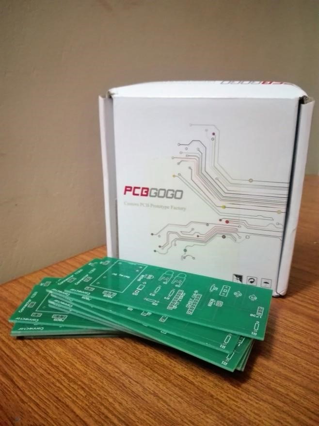
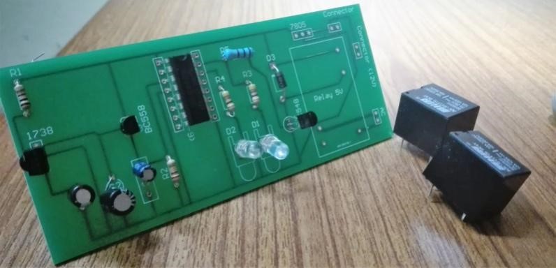
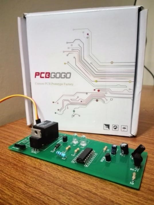
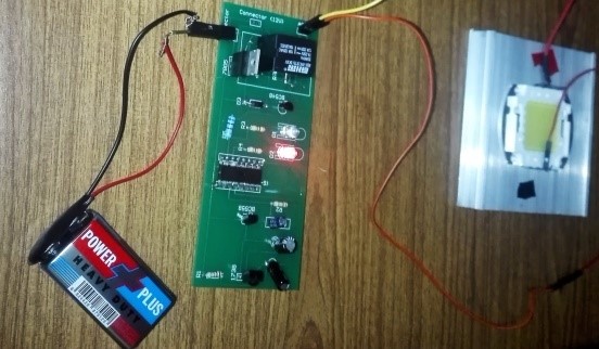
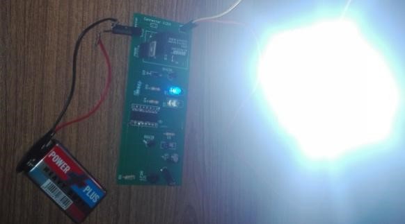
I bought the required components as soon as the PCB package from PCBGOGO arrived. Figure 3 shows the PCBs that I got from them. I ordered 10 pieces to be on the safe side. The PCB was right according to my need and was of super high quality. Figure 4 shows the components placed on the PCB, they are all set to be soldered. Figure 5 shows the final product. And the working of the infrared-based wireless switch is shown in Figure 6. The light is first off, the red LED indicates the OFF state, and when any remote button is pressed, the light turns on. Blue LED indicates the ON state. The details of unboxing the PCB package and soldering the components are available at video link.
Why choose PCBGOGO?
PCBGOGO is one of the biggest manufacturing companies based in China. Their products are top-quality and at the same time are very cheap. The material used for PCB production is the superior quality FR-4 material. It is also fully compliant with UL certificate and ISO 9001:2008 quality management system. After ordering, their on-time shipping is also guaranteed. You don’t need to worry about the delays in delivery. FedEx, DHL, China Post, SF Express are some of the delivery services that are available.
The reasonable prices are also guaranteed, you can buy 10 PCBs for only $5. They also offer discounts on holidays, now they are offering huge Christmas discounts. Surface mount technology services are also offered at prices of as low as $50. So, being an Electrical Engineer, what else can you expect from PCB manufacturing firms? Give us your feedback in the comments below for which projects you will be contacting PCBGOGO. If you have any questions or need any assistance we will be more than happy to help. Simply post your questions.
RELATED POSTS
 3 October, 2019 Marktech reflective sensors feature 0.5-1.5mm short detection distance
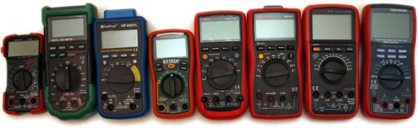 23 July, 2016 Entry Level auto-ranging Digital Multimeters reviewed
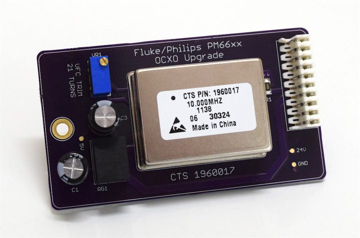 5 May, 2016 Fluke/Philips PM66xx Frequency Counter OCXO Upgrade
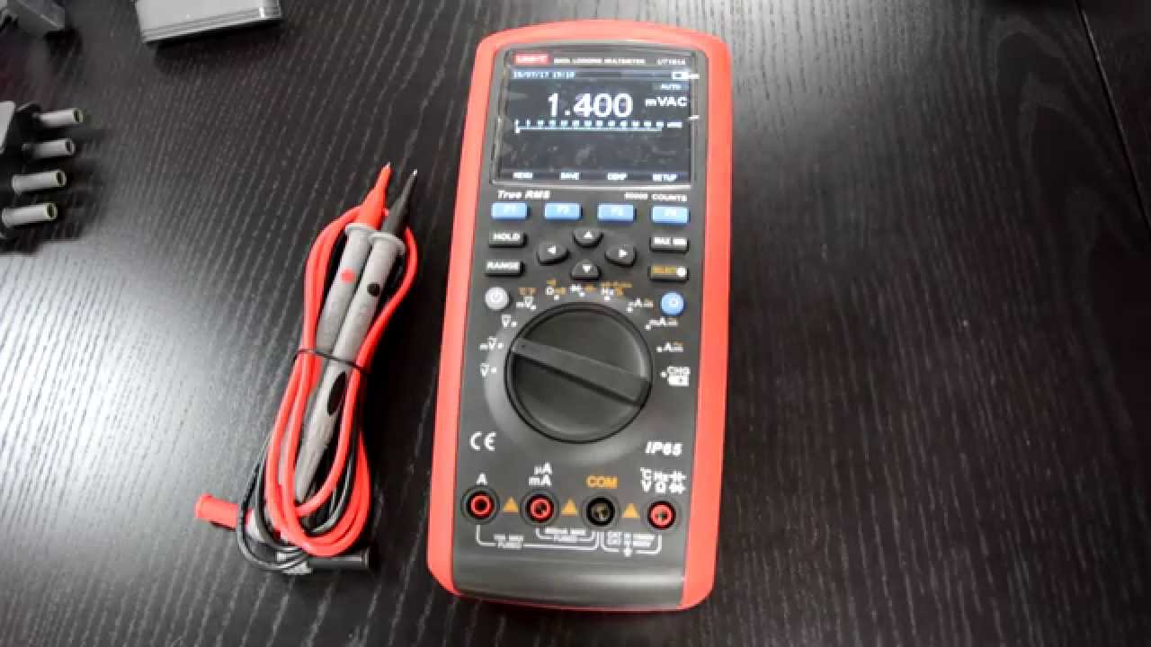 17 December, 2018 UNI-T UT181A – New high end Datalogging Multimeter
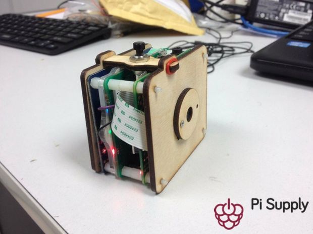 31 July, 2017 A Compact Camera Using Raspberry Pi A+ And Adafruit TFT Display
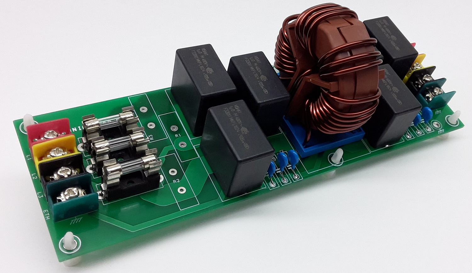 7 December, 2021 3 Phase (3 Wire) EMI Filter – 480VAC


