4.5Amps Bipolar Stepper Motor driver based on TB6600
Bipolar stepper drive board described here has been designed around TB6600HG IC. The TB6600HG is PWM chopper type single chip bipolar sinusoidal micro-step stepping driver.
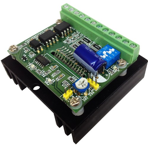
Bipolar stepper drive board described here has been designed around TB6600HG IC. The TB6600HG is PWM chopper type single chip bipolar sinusoidal micro-step stepping driver. Maximum Load 4.5A, Supply 10V to 42V DC.
Features
- Based on Single chip and Second chip for auto half current control
- Suitable for Nema17, Nema23, Nema34 bipolar stepper motors
- Suitable for 4Wires, 6 wires and 8 wires stepper motor.
- Forward and reverse rotations available
- Selectable Phase (Micro-step) drives 1/1, 1/2, 1/4, 1/8, and 1/16
- Maximum Input supply 42V DC Minimum Input supply 10V DC
- Output current 4.5Amps
- Output Fault Monitor LED indicator
- On Board Power LED indicator
- On Board step pulse input indicator
- Standby auto half current reduction circuitry onboard
- Built in Thermal shutdown (IC)
- Built in under voltage lock out (UVLO) circuit (IC)
- Built in over current detection (ISD) circuit (IC)
- Large capacitor to handle inrush current
Applications
- Robotics
- Large format Size Printers
- CNC
- Routers
- 3D Printers
- Machine Automations
- Camera Pan Tilt Heads
- Slot Machine
- Vending Machine
Heat-sink and Thermal Shutdown
The board has current sense resistors and these resistors has been set as per maximum load current 4.5A, If you use lower current motor, please set the PR1-Preset ( Potentiometer) to the required level for the motor. At maximum current load TB6600 IC will overheat in some time and a RED LED turns on. This LED goes off once the temperature falls to a safe operating level.
Micro Stepping
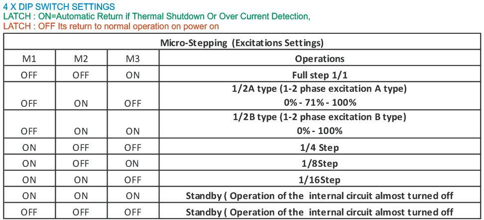
A 4way DIP switch is used to set the micro step modes (Full, Half, Eight, Sixteenth), please see the table for Micro step settings. DIP Switch settings should be changed when power is off so the correct selection is active at power up.
Step Pulse
Minimum positive duty cycle of the input step pulse should be 2.2us and required 5V (TTL) signal. A positive going pulse on the step input activates a step operation.
Current Settings
Average drive current can be set using a Preset (On Board PR1 Potentiometer). CN7 (CT) onboard connector is provided to measure the voltage to set the motor current (torque). Voltage range to set the torque 0.3V to 3.5V
Cautions
- Never connect or remove supply wires, motor wires, or input interface when power is on, this can cause damage to drive.
- Switch the Power to set the Micro stepping
- Before using this drive, please have proper information about stepper motors, Motor impedance, Inductance and other specs.
Inputs
All Inputs are optically isolated to prevent the device for any kind of noise, short circuits.
- Enable: Required 5V DC input, Set high Input disabled the drive, Set low input Enable the drive
- Dir.: Required 5V DC input, Set high Input CW Rotation, Set low input CCW Rotation, Direction of the motor depends how stepper motor has been wired.
- CLK: Step Pulse required 5V DC TTL pulse
Outputs
4 Wires, 6 Wires, 8 Wires Motors can be used with this drive in bipolar mode.
On board LED for Alert
4XDIP SWITCH
SW4 (LATCH): ON=Automatic Return if Thermal Shutdown Or Over Current Detection OCCURS
SW4 (LATCH) : OFF= On Fault condition required power on/off
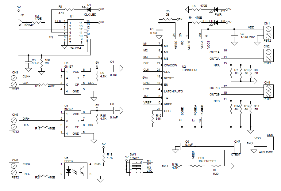
Schematic
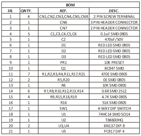
Parts List
Connections
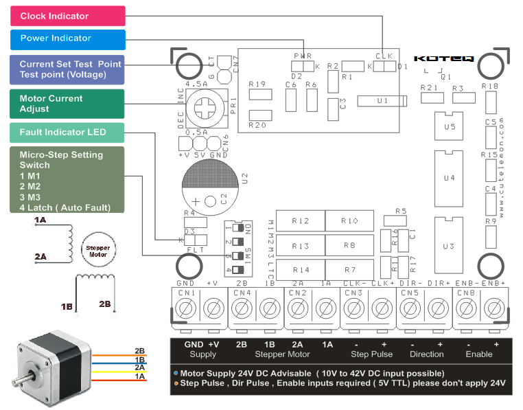
Configuration
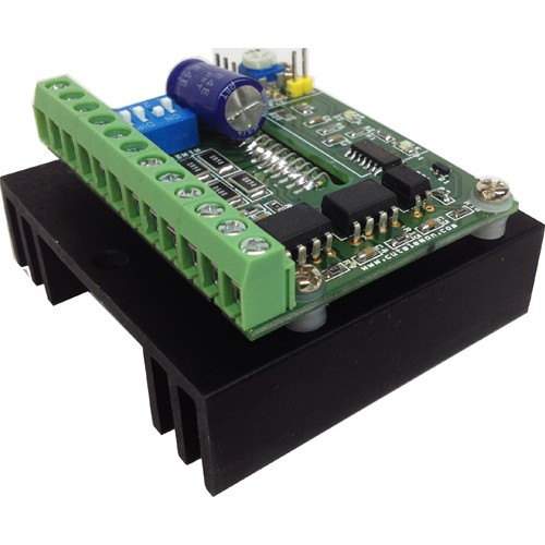
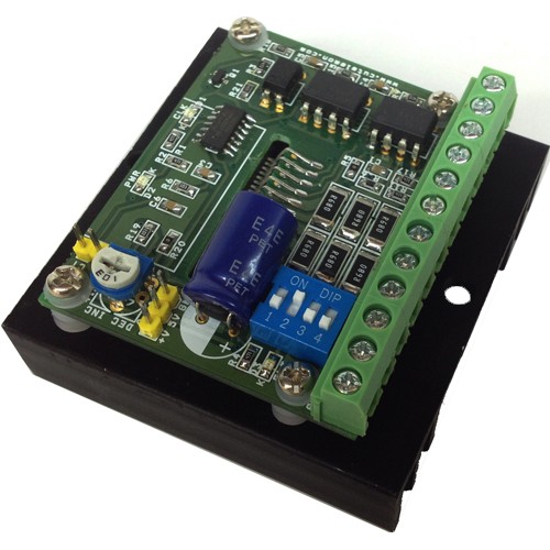
Photos
Great source for Stepper motor drivers. Thanks.
Thanks for your kind comments. We have many more stepper motor driver projects here: https://www.electronics-lab.com/projectcategory/projects/moterlight-and-power-control/
l want to show me some details in this design
What additional information do you need?
Dear Ravindra
It is great that you have published the circuit stepper driver diagram and I want to build it to drive steppers in my CNC. Can you please advise me since the steppers are inductive loads do I have to include diodes to the motor connection or not required?
Thanks
There is no need to add a protection diode to a stepper motor.
Thank you very much and would you please clarify the folowing points
1)Which are the pins of 6N137 to be connected to TB6600 CLK & Dir , Is it the pin no 6.
2) Is it the pin no 4 of PC817 connecting with ENB pin on TB6600
3)pin no 1 CLK on 74hc14, should it to be connected CLK pin of TB6600
4)TB 6600 VREF should be connected which point at the pot Is it to C6 and pot center terminal joint.
Do you sell this PCB and components or is their any place from where I can buy it.
I am a Sri Lankan working in Oman
Regards
Can I use this driver for a DC motor?
This is designed for stepper motors only.
hello,
i’ll be thankful if you gave me a little bit of you time and patience,
i use a TM4C123GH6PM for interpreting Gcode and producing the signals, its a general purpose microcontroller by texas instruments
….
1- i think the optocouplers connections can be reduced, if iam using a 5 volts tolerant controller i can use only 3 pins instead of 6 pins to control DIR,CLK,EN by just connecting all those negative terminals to 2~3 volts. “in my case the controller is 3.3v tolerant so the voltage only will be different”
2- as i read in the datasheet, TQ pin controls the output torque “current”, 100% if high , 30% if low.. so if its high all the time the will heat up the stepper motor , if it’s always low ,,well no torque, so it should follow up the clock signal coming from the controller, when the clock is idle it should be low , when there’s a signal it should be high,
suppose that the controller’s idle clock is a straight low signal, so by creating an RC circuit that ensures that the TQ pins remains high while there’s a signal and will eventually go to low when the clock is idle.
i don’t have access to an oscilloscope right now so i’d like to know what you think.
that’s all for now,
thanks.
Do you have the board design in something like eagle or something else?
We are sorry, design files aren’t available, but you can print your own PCB from the PDF file.
can you give more information for that points plz..
1)Which are the pins of 6N137 to be connected to TB6600 CLK & Dir , Is it the pin no 6.
2) Is it the pin no 4 of PC817 connecting with ENB pin on TB6600
3)pin no 1 CLK on 74hc14, should it to be connected CLK pin of TB6600
4)TB 6600 VREF should be connected which point at the pot Is it to C6 and pot center terminal joint.
1) Yes, 6N137 CLK and DIR pin 6 connects to 21 and 22 of TB6600
2) Yes, correct
3) Yes
4) Yes
HI,
Can TB6600 run Unipolar stepper as well? How to use common wire in unipolar motor?
This will only work with bipolar stepper motors. For unipolar stepper motor drivers, look under the same project category.
Smoke is coming out of my bl tb6600 v1.2 when i increase voltage above 6V.. What should i do?
Please check proper parts alignment and voltage input. Your IC is definitely damaged.
thanks for your reply..
how much is the value of R20 R5
These are 0 Ohm resistors, you can use a simple wire.
hi,
how long is time of monoflop? I mean how long stays TQ high after a step?
Thanks,
Aleksandar
I couldn’t find that information on the datasheet. Probably it stays high for as long as the torque is high.
First thanks for all this great information, i have i question about the design pcb i try to learn pcb design.
so i hope you can help here.
my question is the driver is 4.5AMPS, so the layers A1 A2 B1 B2 need to be able to support this. so this pcb design is 2OZ or 1OZ??
thanks
Yes, the tracks that goes to the motor need to be thick and by using 2oz you will be on the safe side.
can you upload How Gerber Files
I am sorry, Gerber files are not available for this project. However you can make your own PCB using the PDF files above.
Great project, thank…. Can I use this with mach 3 CNC controller board… Regards
To drive this board you need a 5V DC TTL pulse and apply logic on the inputs. So it can be used with any controller able to produce those signals. It can be MACH 3 CNC board or any other controller of MCU.
I am looking for this Assembly 2 numbers . Where can I get?
We can produce this board if order is >25 pieces.