DIY Arduino Uno LCD Voltmeter
Voltage is one of the fundamental values when dealing with electronics. It determines the amount and direction of current flow and represents the potential (electric charge) difference between two points, thus it is somewhat impossible to build or troubleshoot electronics circuits without being faced with the need to measure the voltage at one point or the other.
Voltage is one of the fundamental values when dealing with electronics. It determines the amount and direction of current flow and represents the potential (electric charge) difference between two points, thus it is somewhat impossible to build or troubleshoot electronics circuits without being faced with the need to measure the voltage at one point or the other. The instrumentation device used for measuring the voltage is called a Voltmeter and for today’s tutorial, I will be demonstrating how you can build your own DIY version using an Arduino.
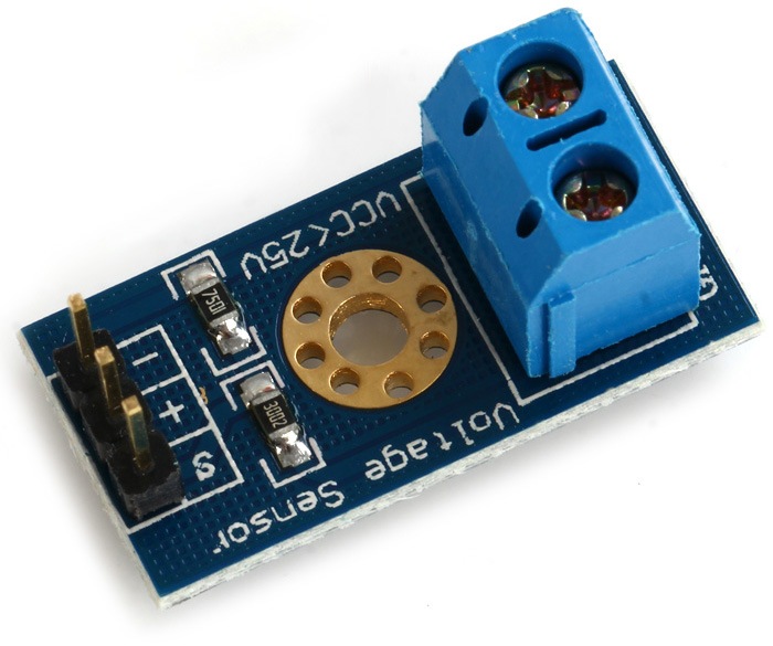
Since voltage could either be direct (DC) or alternating (AC), one can either measure the AC or the DC voltage. For today’s tutorial, to keep things simple, we will focus on the measurement of voltage in a DC-based setup using the B25 voltage sensor module.
The B25 voltage sensor is a cheap, 25v maximum input, analog sensor which uses the voltage divider principle to give a value on output, corresponding to the input voltage. The sensor uses a linear conversion system such as that the value at the output is directly proportional to the input, thus, when working with the Arduino, it is important to ensure that a voltage greater than 25V is not applied at the module’s input as this will drive the voltage at the output beyond 5v which may lead to your Arduino board being damaged. While the sensor is probably cheap enough, you could build your own version using two resistors, set up as a voltage divider.
While several AC measuring principles exist, we can use a DC voltmeter to measure AC voltage but this should only be done after rectification and regulation of the input to a value tolerable by the DC side of the system. Correlation and mapping can then be done to indicate the value of AC voltage represented by the DC voltage (e.g 5VDC could represent 220VAC).
A major application of this project could be to keep track of the battery life of your project.
Required Components
The following components are required to build this project;
As usual, the exact one used for this tutorial can be bought via the link attached to them.
Schematics
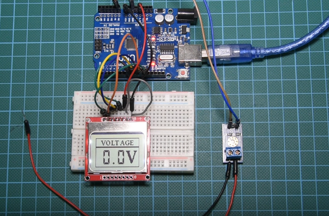
The schematics for this project is quite easy. Connect the components as shown below.
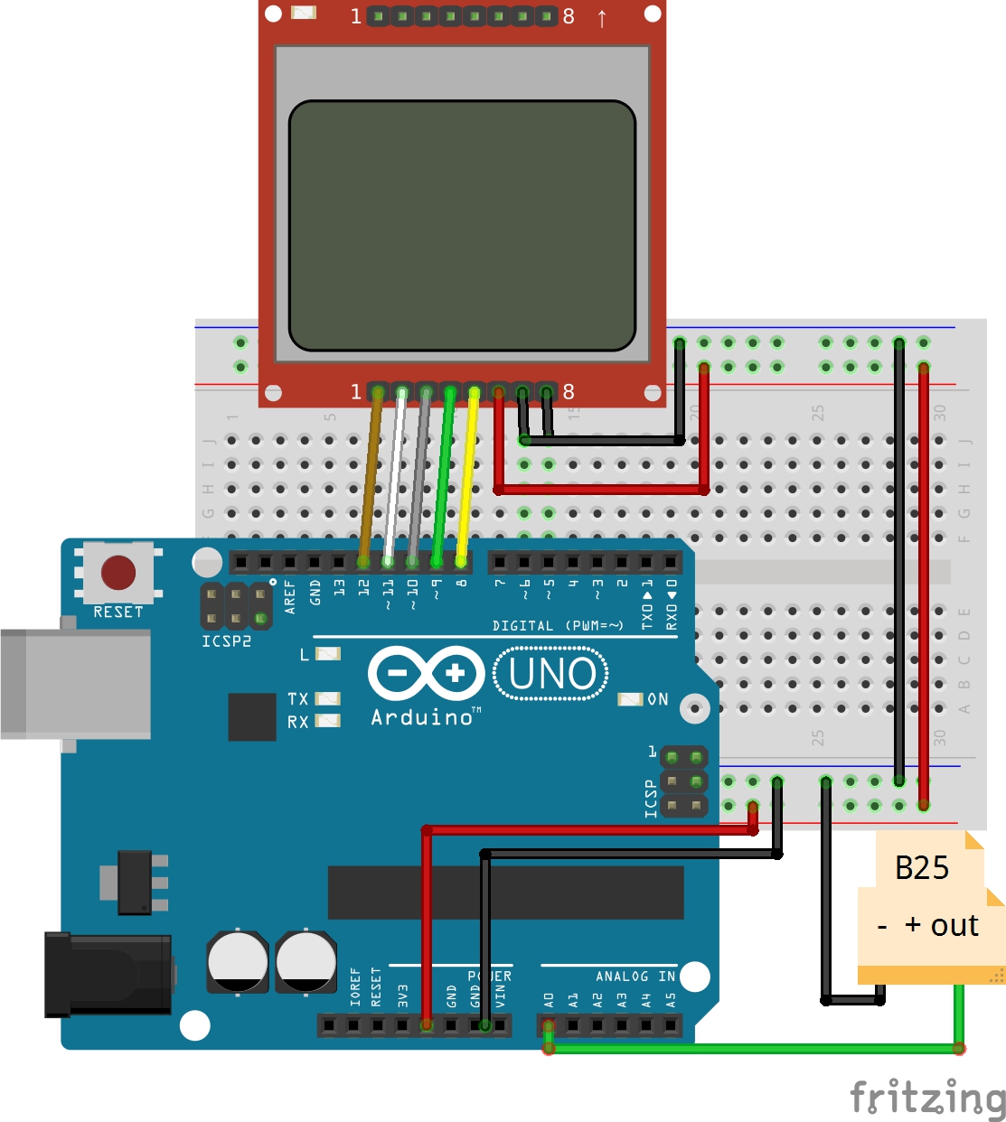
As mentioned earlier, the B25 voltage sensor is an analog device as such, its output is connected to the analog pin of the Arduino. To make the schematics easier to follow there is a breakdown of how the devices are connected, pin to pin.
Arduino – Voltage Sensor
GND - GND
A0 - Out
Nokia 5110 – Arduino
Pin 1(RST) – D12
Pin 2(CE) – D11
Pin 3(DC) – D10
Pin 4(DIN) – D9
Pin 5(CLK) – D8
Pin 6(VCC) - VCC
Pin 7(LIGHT) - GND
Pin 8(GND) - GND
We have done quite a number of tutorials which involves the use of the Nokia 5110 LCD. You may want to check one of them (especially this one) to better understand its connection and use.
With the connections done, we are now ready to write the code.
Code
The code for this project is quite simple. All we need to do is to read the voltage of the voltage sensor, convert it to the corrresponding voltage and display the value on the Nokia 5110 LCD Display. To display the information in a user-friendly manner, we will create a user interface for the LCD display which is attached together with the code in the zip file under the download section. We covered how to develop a user interface in one of the previous tutorials. To easily write the code to interface with the Nokia 5110 LCD display, we used the LCD5110_Graph library which can be downloaded from the link attached.
To do a run-through of the code; we will start by including the header files of the libraries that will be used, after which we create an object of the LCD library, specifying the pins of the Arduino to which the LCD is connected.
//written by Nick Koumaris
//info@educ8s.tv
#include <LCD5110_Graph.h> // THE LIBRARY I AM USING IS THIS:  http://www.rinkydinkelectronics.com/library.php?id=47

LCD5110 lcd(8,9,10,12,11);
Next, we specify the variable name to hold the font style, the UI, and the splash screen graphics after which we declare the analog pin of the microcontroller to which, the signal pin of the voltage sensor is connected.
extern unsigned char BigNumbers[];
extern uint8_t ui[];
extern uint8_t startScreen[];

float voltage = 0.0;
int sensorPin = A0;
We then declare some of the other variables that will be used.
float sensorValue = 0.0f;
String voltageString ="0.0";
int stringLength = 0;

float vout = 0.0;
float vin = 0.0;
float R1 = 30000.0;
float R2 = 7500.0;
Next is the void setup function. Here, we initialize the serial port and LCD after which, we issue the command to display the splash screen and set the font style to be used to display text on the LCD.
void setup() {
  Serial.begin(9600);
  lcd.InitLCD();
  lcd.drawBitmap(0, 0, startScreen, 84, 48);
  lcd.update();
  delay(3000);
  lcd.setFont(BigNumbers);
  delay(1000);
}
Next is the void loop function. The task under this section is simple; call the read voltage function to obtain the voltage value and display the value on the serial monitor and the LCD. The value is converted to a string for easy display on the LCD and a delay of 1000ms is applied after it has been displayed, just so it stays long enough on the screen to be seen before the Arduino code loops.
void loop() {
  lcd.clrScr();
  lcd.drawBitmap(0, 0, ui, 84, 48);

  voltage = readVoltage();

  Serial.println(voltage);

  voltageString = String(voltage,1);

  stringLength = voltageString.length();
  displayVoltage(stringLength);
  lcd.update();
  delay(1000);
}
The complete code for the project is shown below and also attached in a zip file under the download section.
//written by Nick Koumaris
//info@educ8s.tv
#include <LCD5110_Graph.h> // THE LIBRARY I AM USING IS THIS:  http://www.rinkydinkelectronics.com/library.php?id=47


LCD5110 lcd(8,9,10,12,11);

extern unsigned char BigNumbers[];
extern uint8_t ui[];
extern uint8_t startScreen[];

float voltage = 0.0;
int sensorPin = A0;
float sensorValue = 0.0f;
String voltageString ="0.0";
int stringLength = 0;

float vout = 0.0;
float vin = 0.0;
float R1 = 30000.0;
float R2 = 7500.0;

void setup() {
  Serial.begin(9600);
  lcd.InitLCD();
  lcd.drawBitmap(0, 0, startScreen, 84, 48);
  lcd.update();
  delay(3000);
  lcd.setFont(BigNumbers);
  delay(1000);
}

void loop() {
  lcd.clrScr();
  lcd.drawBitmap(0, 0, ui, 84, 48);

  voltage = readVoltage();

  Serial.println(voltage);

  voltageString = String(voltage,1);

  stringLength = voltageString.length();
  displayVoltage(stringLength);
  lcd.update();
  delay(1000);
}


float readVoltage()
{

   sensorValue = analogRead(sensorPin);
   vout = (sensorValue * 5.0) / 1024.0;
   vin = vout / (R2/(R1+R2));
   return vin;
}

void displayVoltage(int length)
{
  switch(length)
  {
    case 3:  lcd.print(voltageString,14,19); break;
    case 4:  lcd.print(voltageString,2,19); break;
    default:  lcd.print(voltageString,2,19); break;
  }
}
Demo
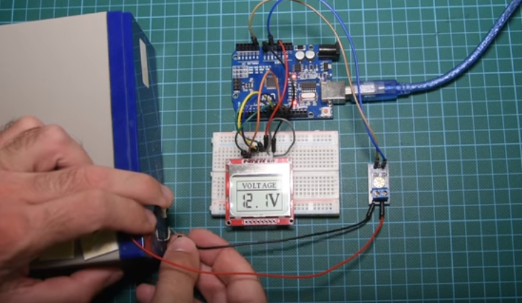
Upload the code to your Arduino and test with any battery or DC source you have. Ensure you don’t exceed the maximum input voltage of 25V so you don’t damage the Arduino. The LCD display should display the voltage level as shown in the picture below.
That’s it for this tutorial guys. Kindly drop any question or comments under the comments section. Will try to reply to as many as possible.
Till next time!
The video version of this tutorial can be found on youtube.