5V/2A Synchronous DC-DC Converter IC Evaluation Kit
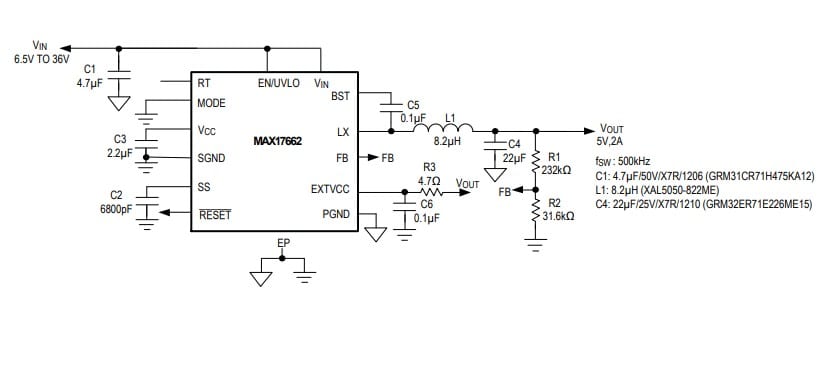
The MAX17662BEVKITB# evaluation kit (EV kit) from Maxim Integrated Products provides a proven design to evaluate the MAX17662B high-efficiency, synchronous step-down dc-dc converter. The EV kit provides 5V/2A at the output from a 6.5V to 36V input supply.
The MAX17662BEVKITB# evaluation kit (EV kit) from Maxim Integrated Products provides a proven design to evaluate the MAX17662B high-efficiency, synchronous step-down dc-dc converter. The EV kit provides 5V/2A at the output from a 6.5V to 36V input supply.
Applications are expected to include base station power supplies, distributed supply regulation, general-purpose point-of-load, high-voltage single-board systems, industrial control power supplies, wall transformer regulation, and so on.
The switching frequency of the EV kit is preset to 500kHz for optimum efficiency and component size. The EV kit features adjustable input under-voltage lockout, adjustable soft-start, open-drain active-low RESET signal.
The EV kit also provides a good layout example, which is optimized for conducted, radiated EMI, and thermal performance.
Hot Plug-In and Long Input Cables
The MAX17662BEVKITB# PCB layout provides an optional electrolytic capacitor (C6 = 47μF/50V). This capacitor limits the peak voltage at the input of the MAX17662B when the dc input source is “hot-plugged” to the EV kit input terminals with long input cables. The equivalent series resistance (ESR) of the electrolytic capacitor dampens the oscillations caused by interaction of the inductance of the long input cables, and the ceramic capacitors at the buck converter input.
Summary of Key Features
- Operates from a 6.5V to 36V Input Supply
- 5V Output Voltage
- Delivers Up to 2A Output Current
- 500kHz Switching Frequency
- Enable/Undervoltage Lockout Input, Resistor- Programmable UVLO Threshold
- Adjustable Soft-Start Time
- Open-Drain Active-Low RESET Output
- Overcurrent and Overtemperature Protection
- Proven PCB Layout
- Fully Assembled and Tested
- Compliance with CISPR22(EN55022) Class B Conducted and Radiated Emissions
Electromagnetic Interference
Compliance to conducted emissions (CE) standards requires an EMI filter at the input of a switching power converter. The EMI filter attenuates high-frequency currents drawn by the switching power converter, and limits the noise injected back into the input power source. The MAX17662BEVKITB# has designated footprints on the EV kit for placement of EMI filter components. Use of these filter components results in lower conducted emissions, below CISPR22 Class B limits. Cut open the trace on L2 before installing conducted EMI filter components.
The MAX17662BEVKITB# PCB layout is also designed to limit radiated emissions from switching nodes of the power converter, resulting in radiated emissions below CISPR22 Class B limits.


