Adjustable Load powered by LT3080 Regulator
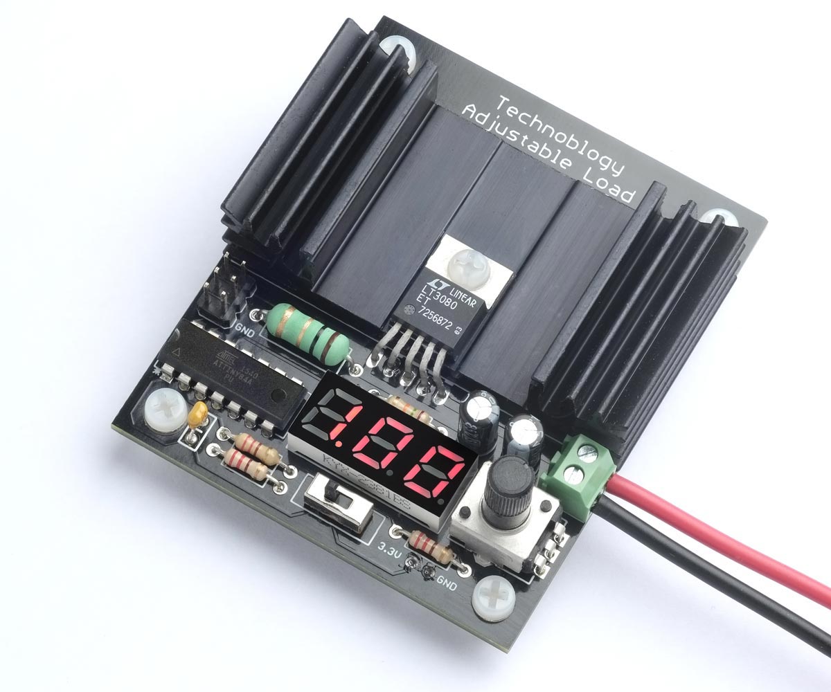
Technoblogy has posted details about an adjustable load that provides a constant-current load for testing power supplies and batteries. It enables you to set the load current to up to 1.05A, using a potentiometer, and displays the current on a three-digit LED display controlled by an ATtiny84.
Technoblogy has posted details about an adjustable load that provides a constant-current load for testing power supplies and batteries. It enables you to set the load current to up to 1.05A, using a potentiometer, and displays the current on a three-digit LED display controlled by an ATtiny84. The adjustable load can be used for more than just testing power supplies; it can also be used to test rechargeable NiMH and Li-ion batteries under different load conditions. It measures the current over time and displays the battery’s capacity in mAh or Ah. This is helpful for determining which battery brand is best, or if a battery needs to be replaced.
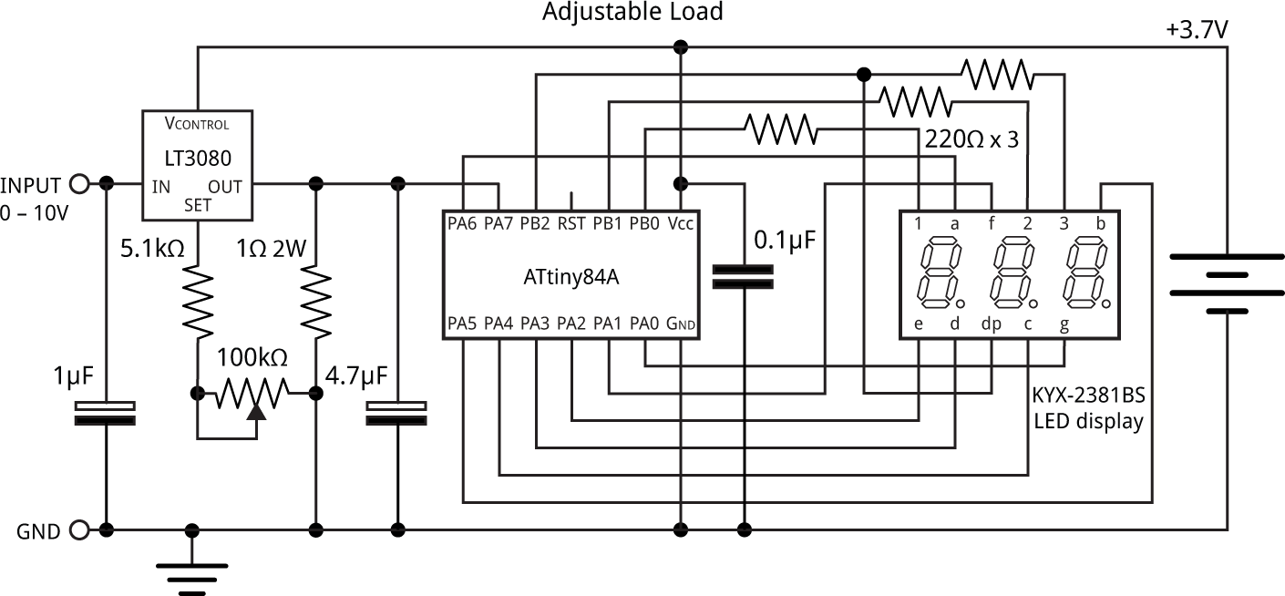
The constant-current circuit is based on an LT3080 regulator, which uses a current reference of 10µA, rather than a voltage reference like regulators such as the LM317. This regulator will operate down to 1.5V and a few mA, and is sensed by a 1Ω resistor, which is fed to the sense input of the regulator, via a 100kΩ potentiometer and 5.1kΩ resistor. The output of the regulator is maintained at 1.05V across the 1Ω resistor, producing a constant current of 1.05A. The LT3080 is available in a few different packages, with the TO220-5 package providing a separate VCONTROL pin, and is convenient to mount on a heatsink. The current is displayed on a three-digit 7-segment display, with a 0.28″ three-digit common anode seven-segment LED display being used.
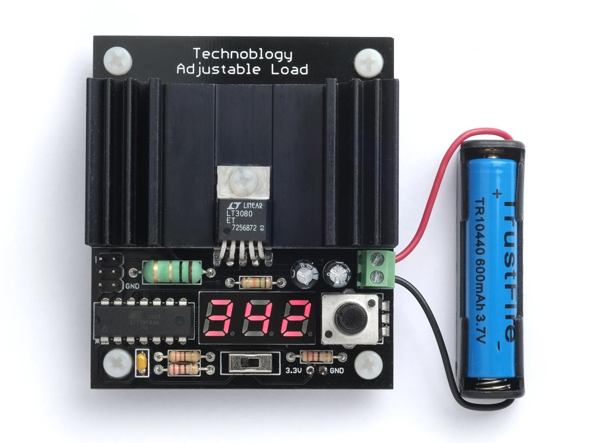
A separate 3.7V Lipo battery is used to power the ATtiny84 and display, as this allows for testing inputs down to as low as 1V, and ensures that the microcontroller and display remain powered even when the test supply drops to zero. The potentiometer is a 100kΩ linear type, with an Alps Alpine RK09K1130C94 or Bourns PTV09A-4020U-B104 being suitable. The 5.1kΩ series resistor is added to be able to adjust the current slightly above 1A. The VCONTROL voltage must be more than 1.2V to 1.35V greater than the output voltage, and is connected to the 3.7V supply used to power the ATtiny84 and display, allowing for the adjustable load to control to as low as 1V.
The PCB was designed in Eagle and ordered from PCBWay. It was designed to fit the heatsink used, which has a thermal rating of 6.8°C/W. The total current consumption of the controller is about 10mA and it is powered by a small 3.7V Lipo cell. The PCB includes space for a 2×3 pin ICSP connector to program the ATtiny84A. All the components are through-hole, so it should be easy to solder by hand. The TO-220 LT3080 is designed for vertical mounting and needs to be gently bent with a pair of flat-nose pliers to fit the PCB. The 1Ω 2W resistor is mounted slightly above the board to improve airflow around it. The PCB also provides a 2.35″ x 1.25″ area of copper which can be used as a heatsink.
For more information about the adjustable load, visit the project page.


