Analog Clock Motor Driver Implementation Using GreenPAK™
Introduction Even in a digital world, classic analog clocks have a timeless style. This simple but universal technology is presented in the article.
Introduction
Even in a digital world, classic analog clocks have a timeless style. This simple but universal technology is presented in the article. The implemented project uses a dual-rail GreenPAK™ SLG46121 which can perform all the active electronic functions needed in an analog clock, including motor driver and crystal oscillator. Additionally, GreenPAK ICs are low-cost and tiny devices that fit right in with smartwatches. As an easy-to-build demonstration, the author obtained a cheap wall clock, removed the existing board, and replaced all the active electronics with one GreenPAK device.
Background: Lavet Type Stepper Motors
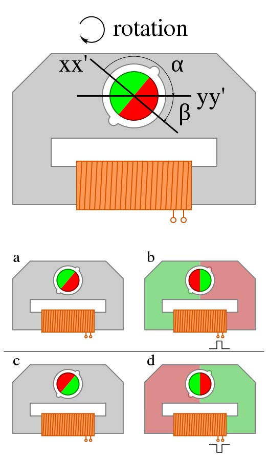
A typical analog clock uses a Lavet type stepper motor to turn the pinion gear of the clock mechanism. It is a single-phase motor that consists of a flat stator (stationary part of the motor) with an inductive coil wrapped around an arm. Between the arms of the stator lies the rotor (moving part of the motor) which consists of a circular permanent magnet with a pinion gear attached to the top of it. The pinion gear coupled with other gears moves the clock hands. The motor works by alternating the polarity of the current in the stator coil with a pause between the polarity changes. During current pulses, the induced magnetism pulls the motor to align the poles of the rotor and stator. While the current is off, the motor is pulled to one of two other positions by reluctant force. These reluctance rest positions are engineered by the design of non-uniformities (notches) in the metal motor housing so that the motor rotates in one direction (see Figure 1).
Motor Driver
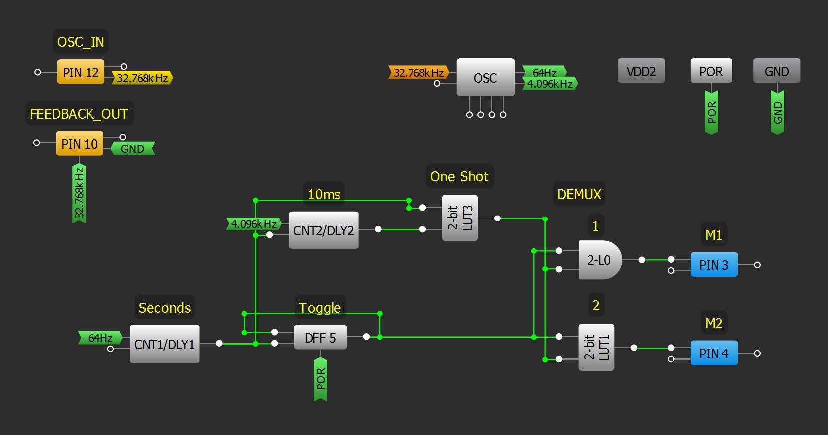
The attached design uses an SLG46121V to produce the required current waveforms through the stator coil. Separate 2x push-pull outputs on the IC (labeled M1 and M2) connect to each end of the coil and drive the alternating pulses. It is necessary to use push-pull outputs for this device to operate correctly.
The waveform consists of a 10 ms pulse each second, alternating between M1 and M2 with each pulse. The pulses are created with just a few blocks driven from a simple 32.768 kHz crystal oscillator circuit. The OSC block conveniently has built-in dividers to help divide down the 32.768 kHz clock. CNT1 outputs a clock pulse every second. This pulse triggers a 10 ms one-shot circuit. Two LUTs (labeled 1 and 2) demultiplex the 10 ms pulse to the output pins. Pulses are passed to M1 when DFF5 output is high, M2 when low.
Crystal Oscillator
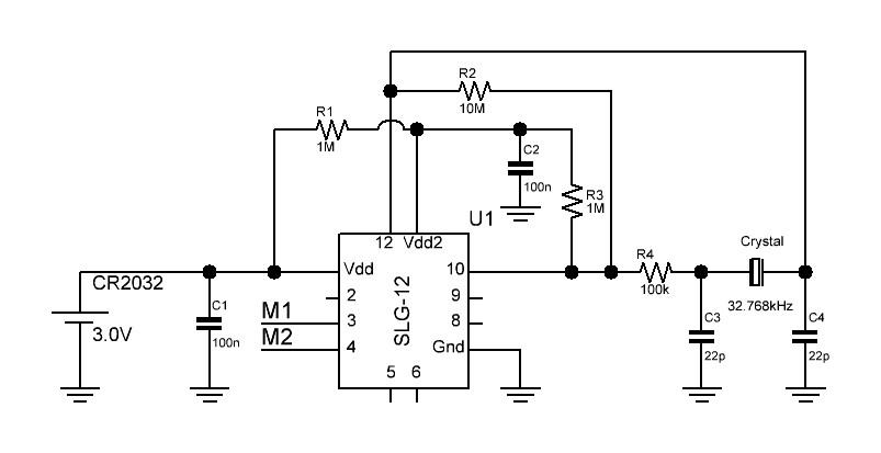
The 32.768 kHz crystal oscillator uses just two pin blocks on the chip. PIN12 (OSC_IN) is set as a low-voltage digital input (LVDI), which has a relatively low switching current. The signal from PIN12 feeds into the OE of PIN10 (FEEDBACK_OUT). PIN10 is configured as a 3-state output with input wired to the ground, making it act like an open drain NMOS output. This signal path naturally inverts, so no other block is needed. Externally, the PIN 10 output is pulled up to VDD2 (PIN11) by a 1MΩ resistor (R4). Both PIN10 and PIN12 are powered by the VDD2 rail, which in-turn is current limited 1 MΩ resistor to VDD. R1 is a feedback resistor to bias the inverting circuit, and R2 limits the output drive. Adding the crystal and capacitors completes the Pierce oscillator circuit as shown in Figure 3.
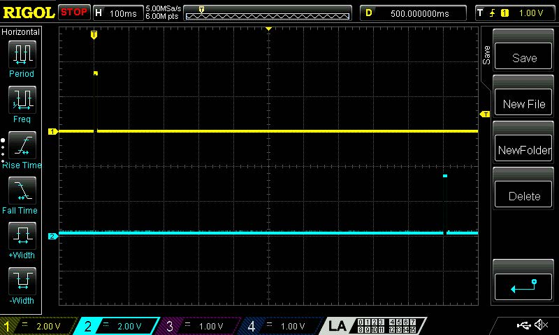
Results
VDD was powered by a CR2032 lithium coin battery which typically provides 3.0 V (3.3 V when fresh). The output waveform consists of alternating 10 ms pulses as shown below in Figure 4. Averaged over a minute, the measured current draw was roughly 97 uA including the motor drive. Without the motor, the current draw was 2.25 μA.
Conclusion
This article demonstrates the usage of a GreenPAK IC aimed to create a complete solution for driving an analog clock stepper motor. This example can be the basis for other more specialized solutions. This solution only uses a portion of the GreenPAK IC resources, which leaves the circuit open to additional functions limited only to the designer imagination.
The complete design file in .gp format might be found here. The design was developed in free software – GreenPAK Designer and was created using the GreenPAK Development Kit.


